Page 1801 of 2543
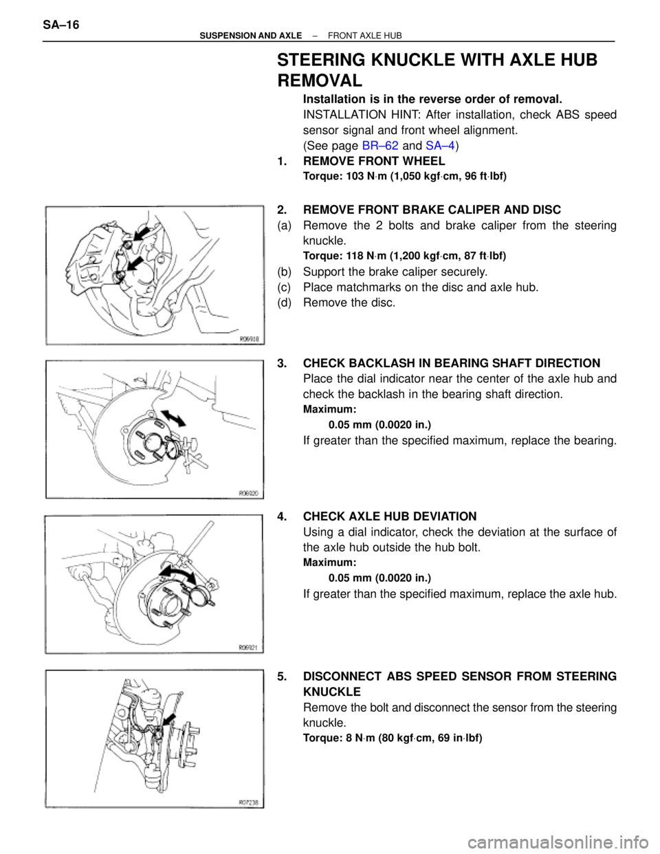
STEERING KNUCKLE WITH AXLE HUB
REMOVAL
Installation is in the reverse order of removal.
INSTALLATION HINT: After installation, check ABS speed
sensor signal and front wheel alignment.
(See page BR±62 and SA±4)
1. REMOVE FRONT WHEEL
Torque: 103 NVm (1,050 kgfVcm, 96 ftVlbf)
2. REMOVE FRONT BRAKE CALIPER AND DISC
(a) Remove the 2 bolts and brake caliper from the steering
knuckle.
Torque: 118 NVm (1,200 kgfVcm, 87 ftVlbf)
(b) Support the brake caliper securely.
(c) Place matchmarks on the disc and axle hub.
(d) Remove the disc.
3. CHECK BACKLASH IN BEARING SHAFT DIRECTION
Place the dial indicator near the center of the axle hub and
check the backlash in the bearing shaft direction.
Maximum:
0.05 mm (0.0020 in.)
If greater than the specified maximum, replace the bearing.
4. CHECK AXLE HUB DEVIATION
Using a dial indicator, check the deviation at the surface of
the axle hub outside the hub bolt.
Maximum:
0.05 mm (0.0020 in.)
If greater than the specified maximum, replace the axle hub.
5. DISCONNECT ABS SPEED SENSOR FROM STEERING
KNUCKLE
Remove the bolt and disconnect the sensor from the steering
knuckle.
Torque: 8 NVm (80 kgfVcm, 69 inVlbf)
SA±16± SUSPENSION AND AXLEFRONT AXLE HUB
Page 1802 of 2543
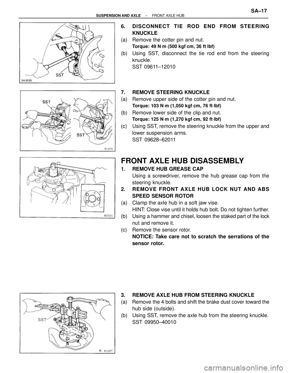
6. DISCONNECT TIE ROD END FROM STEERING
KNUCKLE
(a) Remove the cotter pin and nut.
Torque: 49 NVm (500 kgfVcm, 36 ftVlbf)
(b) Using SST, disconnect the tie rod end from the steering
knuckle.
SST 09611±12010
7. REMOVE STEERING KNUCKLE
(a) Remove upper side of the cotter pin and nut.
Torque: 103 NVm (1,050 kgfVcm, 76 ftVlbf)
(b) Remove lower side of the clip and nut.
Torque: 125 NVm (1,270 kgfVcm, 92 ftVlbf)
(c) Using SST, remove the steering knuckle from the upper and
lower suspension arms.
SST 09628±62011
FRONT AXLE HUB DISASSEMBLY
1. REMOVE HUB GREASE CAP
Using a screwdriver, remove the hub grease cap from the
steering knuckle.
2. REMOVE FRONT AXLE HUB LOCK NUT AND ABS
SPEED SENSOR ROTOR
(a) Clamp the axle hub in a soft jaw vise.
HINT: Close vise until it holds hub bolt. Do not tighten further.
(b) Using a hammer and chisel, loosen the staked part of the lock
nut and remove it.
(c) Remove the sensor rotor.
NOTICE: Take care not to scratch the serrations of the
sensor rotor.
3. REMOVE AXLE HUB FROM STEERING KNUCKLE
(a) Remove the 4 bolts and shift the brake dust cover toward the
hub side (outside).
(b) Using SST, remove the axle hub from the steering knuckle.
SST 09950±40010
± SUSPENSION AND AXLEFRONT AXLE HUBSA±17
Page 1804 of 2543
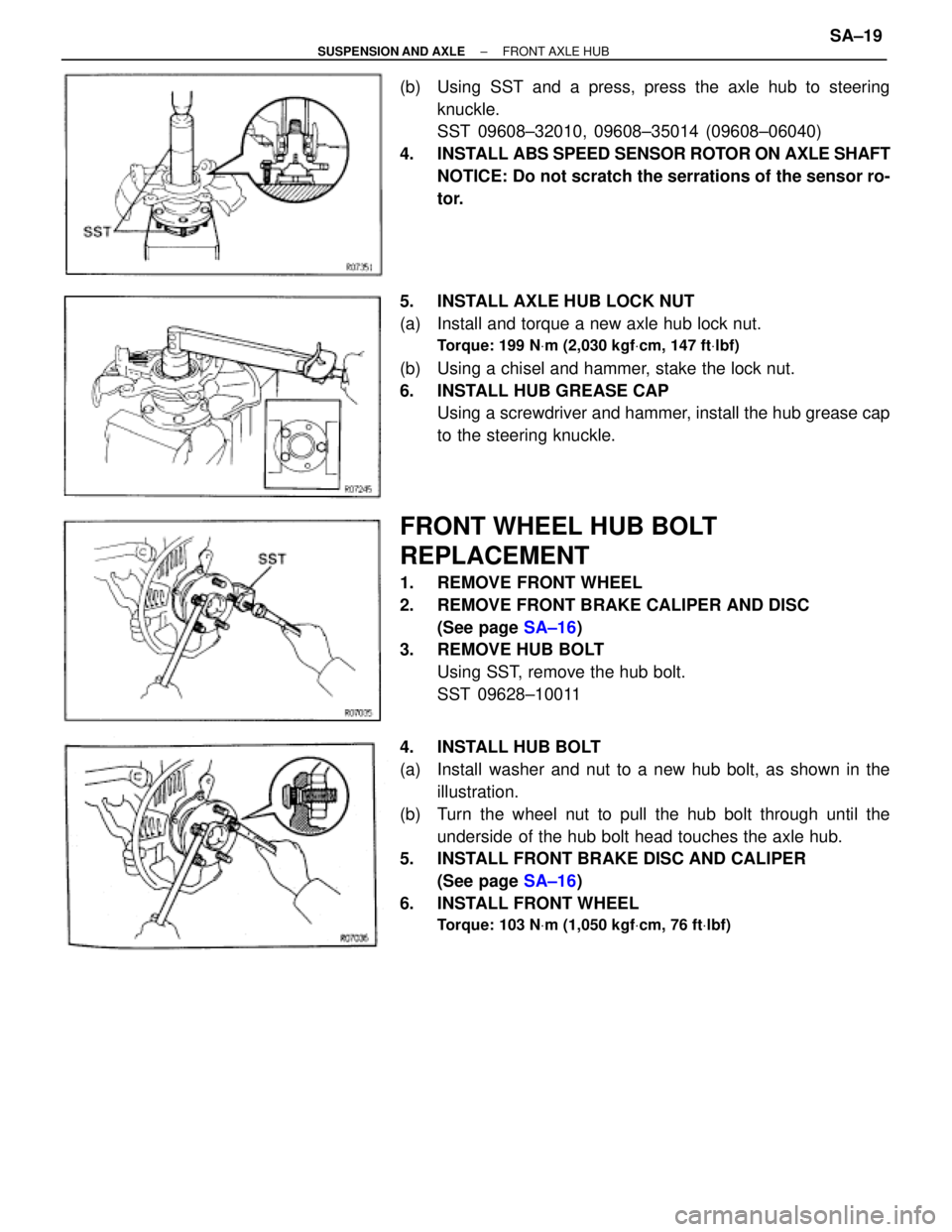
(b) Using SST and a press, press the axle hub to steering
knuckle.
SST 09608±32010, 09608±35014 (09608±06040)
4. INSTALL ABS SPEED SENSOR ROTOR ON AXLE SHAFT
NOTICE: Do not scratch the serrations of the sensor ro-
tor.
5. INSTALL AXLE HUB LOCK NUT
(a) Install and torque a new axle hub lock nut.
Torque: 199 NVm (2,030 kgfVcm, 147 ftVlbf)
(b) Using a chisel and hammer, stake the lock nut.
6. INSTALL HUB GREASE CAP
Using a screwdriver and hammer, install the hub grease cap
to the steering knuckle.
FRONT WHEEL HUB BOLT
REPLACEMENT
1. REMOVE FRONT WHEEL
2. REMOVE FRONT BRAKE CALIPER AND DISC
(See page SA±16)
3. REMOVE HUB BOLT
Using SST, remove the hub bolt.
SST 09628±10011
4. INSTALL HUB BOLT
(a) Install washer and nut to a new hub bolt, as shown in the
illustration.
(b) Turn the wheel nut to pull the hub bolt through until the
underside of the hub bolt head touches the axle hub.
5. INSTALL FRONT BRAKE DISC AND CALIPER
(See page SA±16)
6. INSTALL FRONT WHEEL
Torque: 103 NVm (1,050 kgfVcm, 76 ftVlbf)
± SUSPENSION AND AXLEFRONT AXLE HUBSA±19
Page 1807 of 2543
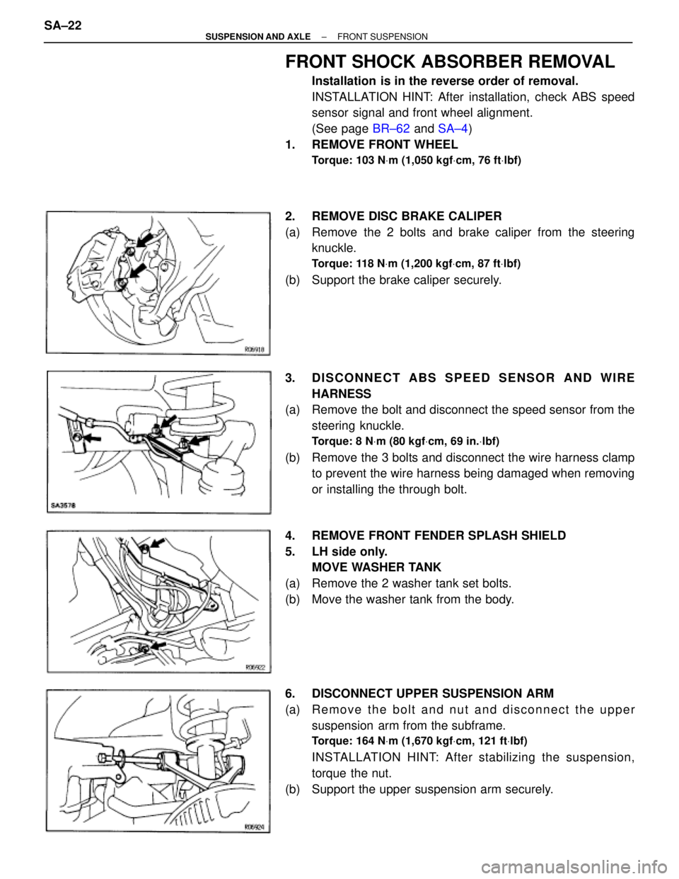
FRONT SHOCK ABSORBER REMOVAL
Installation is in the reverse order of removal.
INSTALLATION HINT: After installation, check ABS speed
sensor signal and front wheel alignment.
(See page BR±62 and SA±4)
1. REMOVE FRONT WHEEL
Torque: 103 NVm (1,050 kgfVcm, 76 ftVlbf)
2. REMOVE DISC BRAKE CALIPER
(a) Remove the 2 bolts and brake caliper from the steering
knuckle.
Torque: 118 NVm (1,200 kgfVcm, 87 ftVlbf)
(b) Support the brake caliper securely.
3. DISCONNECT ABS SPEED SENSOR AND WIRE
HARNESS
(a) Remove the bolt and disconnect the speed sensor from the
steering knuckle.
Torque: 8 NVm (80 kgfVcm, 69 in.Vlbf)
(b) Remove the 3 bolts and disconnect the wire harness clamp
to prevent the wire harness being damaged when removing
or installing the through bolt.
4. REMOVE FRONT FENDER SPLASH SHIELD
5. LH side only.
MOVE WASHER TANK
(a) Remove the 2 washer tank set bolts.
(b) Move the washer tank from the body.
6. DISCONNECT UPPER SUSPENSION ARM
(a) R e m o v e t h e b o l t a n d n u t a n d d i s connect the upper
suspension arm from the subframe.
Torque: 164 NVm (1,670 kgfVcm, 121 ftVlbf)
INSTALLATION HINT: After stabilizing the suspension,
torque the nut.
(b) Support the upper suspension arm securely. SA±22
± SUSPENSION AND AXLEFRONT SUSPENSION
Page 1812 of 2543
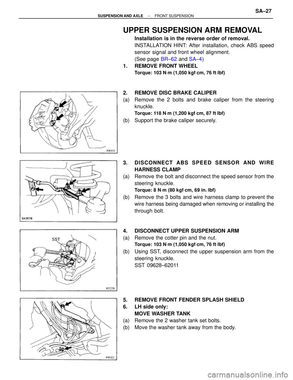
UPPER SUSPENSION ARM REMOVAL
Installation is in the reverse order of removal.
INSTALLATION HINT: After installation, check ABS speed
sensor signal and front wheel alignment.
(See page BR±62 and SA±4)
1. REMOVE FRONT WHEEL
Torque: 103 NVm (1,050 kgfVcm, 76 ftVlbf)
2. REMOVE DISC BRAKE CALIPER
(a) Remove the 2 bolts and brake caliper from the steering
knuckle.
Torque: 118 NVm (1,200 kgfVcm, 87 ftVlbf)
(b) Support the brake caliper securely.
3. DISCONNECT ABS SPEED SENSOR AND WIRE
HARNESS CLAMP
(a) Remove the bolt and disconnect the speed sensor from the
steering knuckle.
Torque: 8 NVm (80 kgfVcm, 69 in.Vlbf)
(b) Remove the 3 bolts and wire harness clamp to prevent the
wire harness being damaged when removing or installing the
through bolt.
4. DISCONNECT UPPER SUSPENSION ARM
(a) Remove the cotter pin and the nut.
Torque: 103 NVm (1,050 kgfVcm, 76 ftVlbf)
(b) Using SST, disconnect the upper suspension arm from the
steering knuckle.
SST 09628±62011
5. REMOVE FRONT FENDER SPLASH SHIELD
6. LH side only:
MOVE WASHER TANK
(a) Remove the 2 washer tank set bolts.
(b) Move the washer tank away from the body.
± SUSPENSION AND AXLEFRONT SUSPENSIONSA±27
Page 1823 of 2543
REAR AXLE CARRIER REMOVAL
Installation is in the reverse order of removal.
INSTALLATION HINT: After installation, check ABS speed
sensor signal and rear wheel alignment.
(See page BR±64 and SA±9)
1. REMOVE REAR WHEEL
Torque: 103 NVm (1,050 kgfVcm, 76 ftVlbf)
2. REMOVE REAR BRAKE CALIPER AND DISC
(a) Remove the 2 bolts and brake caliper from the rear axle hub.
Torque: 104 NVm (1,065 kgfVcm, 77 ftVlbf)
(b) Support the brake caliper securely.
(c) Place matchmarks on the disc and axle hub.
(d) Remove the disc.
3. CHECK BACKLASH IN BEARING SHAFT DIRECTION
Place the dial indicator near the center of the axle hub and
check the backlash in the bearing shaft direction.
Maximum:
0.05 mm (0.0020 in.)
If greater than the specified maximum, replace the bearing. SA±38
± SUSPENSION AND AXLEREAR AXLE HUB
Page 1824 of 2543
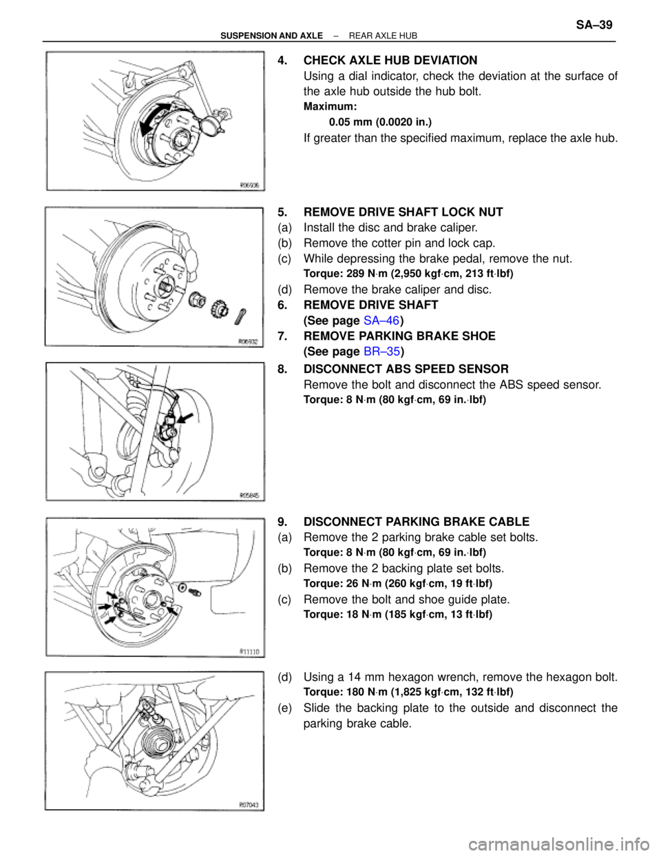
4. CHECK AXLE HUB DEVIATION
Using a dial indicator, check the deviation at the surface of
the axle hub outside the hub bolt.
Maximum:
0.05 mm (0.0020 in.)
If greater than the specified maximum, replace the axle hub.
5. REMOVE DRIVE SHAFT LOCK NUT
(a) Install the disc and brake caliper.
(b) Remove the cotter pin and lock cap.
(c) While depressing the brake pedal, remove the nut.
Torque: 289 NVm (2,950 kgfVcm, 213 ftVlbf)
(d) Remove the brake caliper and disc.
6. REMOVE DRIVE SHAFT
(See page SA±46)
7. REMOVE PARKING BRAKE SHOE
(See page BR±35)
8. DISCONNECT ABS SPEED SENSOR
Remove the bolt and disconnect the ABS speed sensor.
Torque: 8 NVm (80 kgfVcm, 69 in.Vlbf)
9. DISCONNECT PARKING BRAKE CABLE
(a) Remove the 2 parking brake cable set bolts.
Torque: 8 NVm (80 kgfVcm, 69 in.Vlbf)
(b) Remove the 2 backing plate set bolts.
Torque: 26 NVm (260 kgfVcm, 19 ftVlbf)
(c) Remove the bolt and shoe guide plate.
Torque: 18 NVm (185 kgfVcm, 13 ftVlbf)
(d) Using a 14 mm hexagon wrench, remove the hexagon bolt.
Torque: 180 NVm (1,825 kgfVcm, 132 ftVlbf)
(e) Slide the backing plate to the outside and disconnect the
parking brake cable.
± SUSPENSION AND AXLEREAR AXLE HUBSA±39
Page 1828 of 2543
4. INSTALL OIL SEAL (Inner)
(a) Using SST and a hammer, install a new oil seal.
SST 09223±15020
NOTICE: Be careful not to damage the oil seal.
(b) Coat MP grease to the oil seal lip.
5. INSTALL DUST DEFLECTOR
Using SST and a press, install a new dust deflector.
SST 09608±35014 (09608±06020, 09608±06160)
HINT: Align the holes for the ABS speed sensor in the dust
deflector and carrier.
HUB BOLT REPLACEMENT
1. REMOVE REAR WHEEL
2. REMOVE REAR BRAKE CALIPER AND DISC
(See page SA±38)
3. REMOVE HUB BOLT
Using SST, remove the hub bolt.
SST 09628±10011
4. INSTALL HUB BOLT
(a) Install washer and nut to a new hub bolt, as shown in the
illustration.
(b) Turn the wheel nut to pull the hub bolt through until the
underside of the hub bolt head touches the axle hub.
5. INSTALL REAR BRAKE DISC AND BRAKE CALIPER
(See page SA±35)
6. INSTALL REAR WHEEL
Torque: 103 NVm (1,050 kgfVcm, 76 ftVlbf)
± SUSPENSION AND AXLEREAR AXLE HUBSA±43