Page 156 of 2543
A340E (2JZ-GTE) AUTOMATIC TRANSMISSIONOPERATION -
AT-8
4. ELECTRONIC CONTROL SYSTEM
The electronic control system for the A340E automatic transmission provides extremely precise control
of the gear shift timing and lock-up timing in response to driving conditions as sensed by various sen-
sors located throughout the vehicle and in response to the engine's running condition.
In addition, the ECM control reduces vehicle squat when the shift lever is moved from N to D.
The electronic control system is also equipped with a self diagnosis system which diagnoses malfunc-
tions for the vehicle to continue functioning when a malfunction occurs.
CONSTRUCTION
The electronic control system can be broadly divided onto three groups; the sensors, ECM and actua-
tors.
Page 258 of 2543
A340E(Others) AUTOMATIC TRANSMISSIONDESCRIPTION -
AT-1
DESCRIPTION
GENERAL DESCRIPTION
The A340E is a 4-speed, Electronically Controlled Transmission developed for use with high-perfor-
mance engines. A lock-up mechanism is built into the torque converter clutch.
The A340E automatic transmission is mainly composed of the torque converter clutch, the overdrive
(hereafter called O/D) planetary gear unit, a 3-speed planetary gear unit, a hydraulic control system
and an electronic control system.
AT0FT-02
Page 259 of 2543

A340E(Others) AUTOMATIC TRANSMISSIONDESCRIPTION -
AT-2
GENERAL SPECIFICATIONS
TRUCK, 4 RUNNER, T100:
Type of TransmissionA340E
Type of Engine3VZ-E
Torque Converter Clutch Stall Torque RatioC&C, T100 2.0 : 1
Others 2.15 : 1
Lock-up MechanismEquipped
Gear Ratio 1st Gear
2nd Gear
3rd Gear
O/D Gear
Reverse Gear2.804
1.531
1.000
0.705
2.393
Number of Discs and Plates (Disc and Plate)
O/D Direct Clutch (C
0)
Forward Clutch (C
1)
Direct Clutch (C
2)
2nd Brake (B
2)
1st and Reverse Brake (B
3)
O/D Brake (B
0)
2 / 2
5 / 5
4 / 4
5 / 5
6 / 6
4 / 3
B1 Band Width mm (in.)40 (1.57)
ATF TypeATF DEXRON® II
Capacity (US qts, Imp.qts) Total
Drain and Refill7.2 (7.6, 6.3)
1.6 (1.7, 1.4)
SUPRA:
Type of TransmissionA340E
Type of Engine2JZ-GE
Torque Converter Clutch Stall Torque Ratio1.9 : 1
Lock-up MechanismEquipped
Gear Ratio 1st Gear
2nd Gear
3rd Gear
O/D Gear
Reverse Gear2.804
1.531
1.000
0.705
2.393
Number of Discs and Plates (Disc and Plate)
O/D Direct Clutch (C
0)
Forward Clutch (C
1)
Direct Clutch (C
2)
2nd Brake (B
2)
1st and Reverse Brake (B
3)
O/D Brake (B
0)
2 / 2
5 / 5
4 / 4
5 / 5
6 / 6
4 / 3
B1 Band Width mm (in.)40 (1.57)
ATF TypeATF DEXRON® II
Capacity (US qts, Imp.qts) Total
Drain and Refill7.2 (7.6, 6.3)
1.6 (1.7, 1.4)
Page 260 of 2543
A340E(Others) AUTOMATIC TRANSMISSIONDESCRIPTION -
AT-3
PREVIA:
Type of TransmissionA340E
Type of Engine2TZ-FZE
Torque Converter Clutch Stall Torque Ratio2.0 : 1
Lock-up MechanismEquipped
Gear Ratio 1st Gear
2nd Gear
3rd Gear
O/D Gear
Reverse Gear2.804
1.531
1.000
0.705
2.393
Number of Discs and Plates (Disc and Plate)
O/D Direct Clutch (C
0)
Forward Clutch (C
1)
Direct Clutch (C
2)
2nd Brake (B
2)
1st and Reverse Brake (B
3)
O/D Brake (B
0)
2 / 2
5 / 5
4 / 4
5 / 5
6 / 6
3 / 2
B1 Band Width mm (in.)40 (1.57)
ATF TypeATF DEXRON® II
Capacity (US qts, Imp.qts) Total
Drain and Refill7.2 (7.6, 6.3)
1.6 (1.7, 1.4)
Page 265 of 2543

A340E(Others) AUTOMATIC TRANSMISSIONOPERATION -
AT-8
3. HYDRAULIC CONTROL SYSTEM
The hydraulic control system is composed of the oil pump, the valve body, the solenoid valves, and the
clutches and brakes, as well as the fluid passages which connect all of these components. Based on
the hydraulic pressure created by the oil pump, the hydraulic control system governs the hydraulic pres-
sure acting on the torque converter clutch, clutches and brakes in accordance with the vehicle driving
conditions.
There are 3 solenoid valves on the valve body.
The No.1 and No.2 solenoid valves are turned on and off by signals from the ECM to operate the shift
valves and change the gear shift position.
The lock-up solenoid valve is operated by signals from the ECM to engage or disengage the lock-up
clutch of the torque converter clutch.
�LINE PRESSURE
Line pressure is the most basic and important pressure used in the automatic transmission, because
it is used to operate all of the clutches and brakes in the transmission.
If the primary regulator valve does not operate correctly, line pressure will be either too high or too low.
Line pressure that is too high will lead to shifting shock and consequent engine power loss due to the
greater effort required of the oil pump; line pressure that is too low will cause slippage of clutches and
brakes, which will, in extreme cases, prevent the vehicle from moving. Therefore, if either of these prob-
lems are noted, the line pressure should be measured to see if it is within specification.
�THROTTLE PRESSURE
Throttle pressure is always kept in accordance with the opening angle of the engine throttle valve. This
throttle pressure acts on the primary regulator valve and, the line pressure is regulated according to
the throttle valve opening.
In the hydraulically controlled automatic transmission, throttle pressure is used for regulating line pres-
sure and as signal pressure for up-shift and down-shift of the transmission. In the electronically con-
trolled transmission, however, throttle pressure is used only for regulating line pressure. Consequently,
improper adjustment of the transmission throttle cable may result in a line pressure that is too high or
too low. This, in turn, will lead to shifting shock or clutch and brake slippage.
Page 389 of 2543

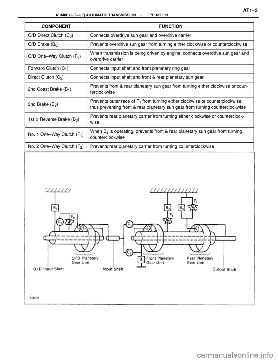
���������� ����������COMPONENT������������������������� �������������������������FUNCTION
���������� ����������O/D Direct Clutch (C0)������������������������� �������������������������Connects overdrive sun gear and overdrive carrier
���������� �
��������� ����������O/D Brake (B0)������������������������� �
������������������������ �������������������������Prevents overdrive sun gear from turning either clockwise or counterclockwise
���������� �
��������� ����������
O/D One±Way Clutch (F0)������������������������� �
������������������������ �������������������������
When transmission is being driven by engine, connects overdrive sun gear and
overdrive carrier
���������� ����������Forward Clutch (C1)������������������������� �������������������������Connects input shaft and front planetary ring gear
���������� ����������Direct Clutch (C2)������������������������� �������������������������Connects input shaft and front & rear planetary sun gear
���������� �
��������� ����������2nd Coast Brake (B1)
������������������������� �
������������������������ �������������������������Prevents front & rear planetary sun gear from turning either clockwise or coun-
terclockwise
���������� �
��������� �
��������� ����������
2nd Brake (B2)
������������������������� �
������������������������ �
������������������������ �������������������������
Prevents outer race of F1 from turning either clockwise or counterclockwise,
thus preventing front & rear planetary sun gear from turning counterclockwise
���������� �
��������� ����������
1st & Reverse Brake (B3)������������������������� �
������������������������ �������������������������
Prevents rear planetary carrier from turning either clockwise or counterclock-
wise
���������� �
��������� ����������No. 1 One±Way Clutch (F1)������������������������� �
������������������������ �������������������������
When B2 is operating, prevents front & rear planetary sun gear from turning
counterclockwise
���������� ����������No. 2 One±Way Clutch (F2)������������������������� �������������������������Prevents rear planetary carrier from turning coiunterclockwise
± AT340E (2JZ±GE) AUTOMATIC TRANSMISSIONOPERATIONAT1±3
Page 392 of 2543

HYDRAULIC CONTROL SYSTEM
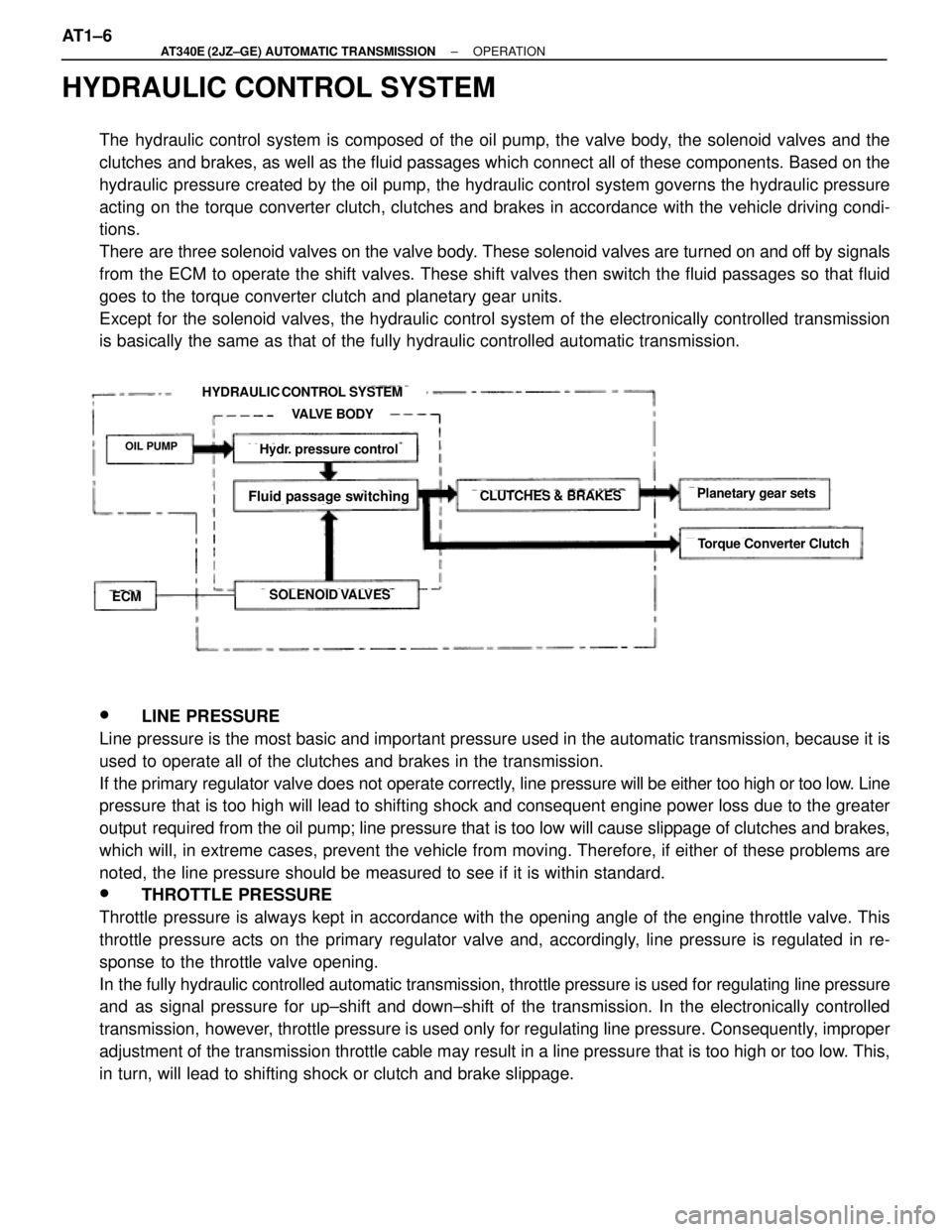
The hydraulic control system is composed of the oil pump, the valve body, the solenoid valves and the
clutches and brakes, as well as the fluid passages which connect all of these components. Based on the
hydraulic pressure created by the oil pump, the hydraulic control system governs the hydraulic pressure
acting on the torque converter clutch, clutches and brakes in accordance with the vehicle driving condi-
tions.
There are three solenoid valves on the valve body. These solenoid valves are turned on and off by signals
from the ECM to operate the shift valves. These shift valves then switch the fluid passages so that fluid
goes to the torque converter clutch and planetary gear units.
Except for the solenoid valves, the hydraulic control system of the electronically controlled transmission
is basically the same as that of the fully hydraulic controlled automatic transmission.
HYDRAULIC CONTROL SYSTEM
VALVE BODY
OIL PUMP
ECMSOLENOID VALVES
CLUTCHES & BRAKES
Hydr. pressure control
Fluid passage switchingPlanetary gear sets
Torque Converter Clutch
w LINE PRESSURE
Line pressure is the most basic and important pressure used in the automatic transmission, because it is
used to operate all of the clutches and brakes in the transmission.
If the primary regulator valve does not operate correctly, line pressure will be either too high or too low. Line
pressure that is too high will lead to shifting shock and consequent engine power loss due to the greater
output required from the oil pump; line pressure that is too low will cause slippage of clutches and brakes,
which will, in extreme cases, prevent the vehicle from moving. Therefore, if either of these problems are
noted, the line pressure should be measured to see if it is within standard.
w THROTTLE PRESSURE
Throttle pressure is always kept in accordance with the opening angle of the engine throttle valve. This
throttle pressure acts on the primary regulator valve and, accordingly, line pressure is regulated in re-
sponse to the throttle valve opening.
In the fully hydraulic controlled automatic transmission, throttle pressure is used for regulating line pressure
and as signal pressure for up±shift and down±shift of the transmission. In the electronically controlled
transmission, however, throttle pressure is used only for regulating line pressure. Consequently, improper
adjustment of the transmission throttle cable may result in a line pressure that is too high or too low. This,
in turn, will lead to shifting shock or clutch and brake slippage. AT1±6
± AT340E (2JZ±GE) AUTOMATIC TRANSMISSIONOPERATION
Page 393 of 2543

ELECTRONIC CONTROL SYSTEM
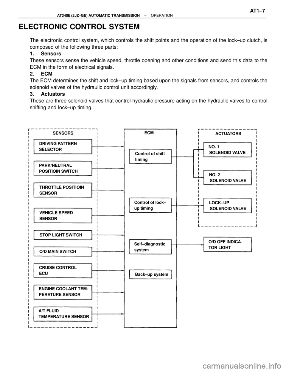
The electronic control system, which controls the shift points and the operation of the lock±up clutch, is
composed of the following three parts:
1. Sensors
These sensors sense the vehicle speed, throttle opening and other conditions and send this data to the
ECM in the form of electrical signals.
2. ECM
The ECM determines the shift and lock±up timing based upon the signals from sensors, and controls the
solenoid valves of the hydraulic control unit accordingly.
3. Actuators
These are three solenoid valves that control hydraulic pressure acting on the hydraulic valves to control
shifting and lock±up timing.
SENSORSECM
DRIVING PATTERN
SELECTOR
PARK/NEUTRAL
POSITIOIN SWITCH
THROTTLE POSITIOIN
SENSOR
VEHICLE SPEED
SENSOR
STOP LIGHT SWITCH
O/D MAIN SWITCH
CRUISE CONTROL
ECU
ENGINE COOLANT TEM-
PERATURE SENSOR
A/T FLUID
TEMPERATURE SENSOR
Back±up system
Self±diagnostic
system
Control of lock±
up timing
Control of shift
timing
ACTUATORS
NO. 1
SOLENOID VALVE
NO. 2
SOLENOID VALVE
LOCK±UP
SOLENOID VALVE
O/D OFF INDICA-
TOR LIGHT
± AT340E (2JZ±GE) AUTOMATIC TRANSMISSIONOPERATIONAT1±7