Page 45 of 2543
(See page IN±30).
AC±22).
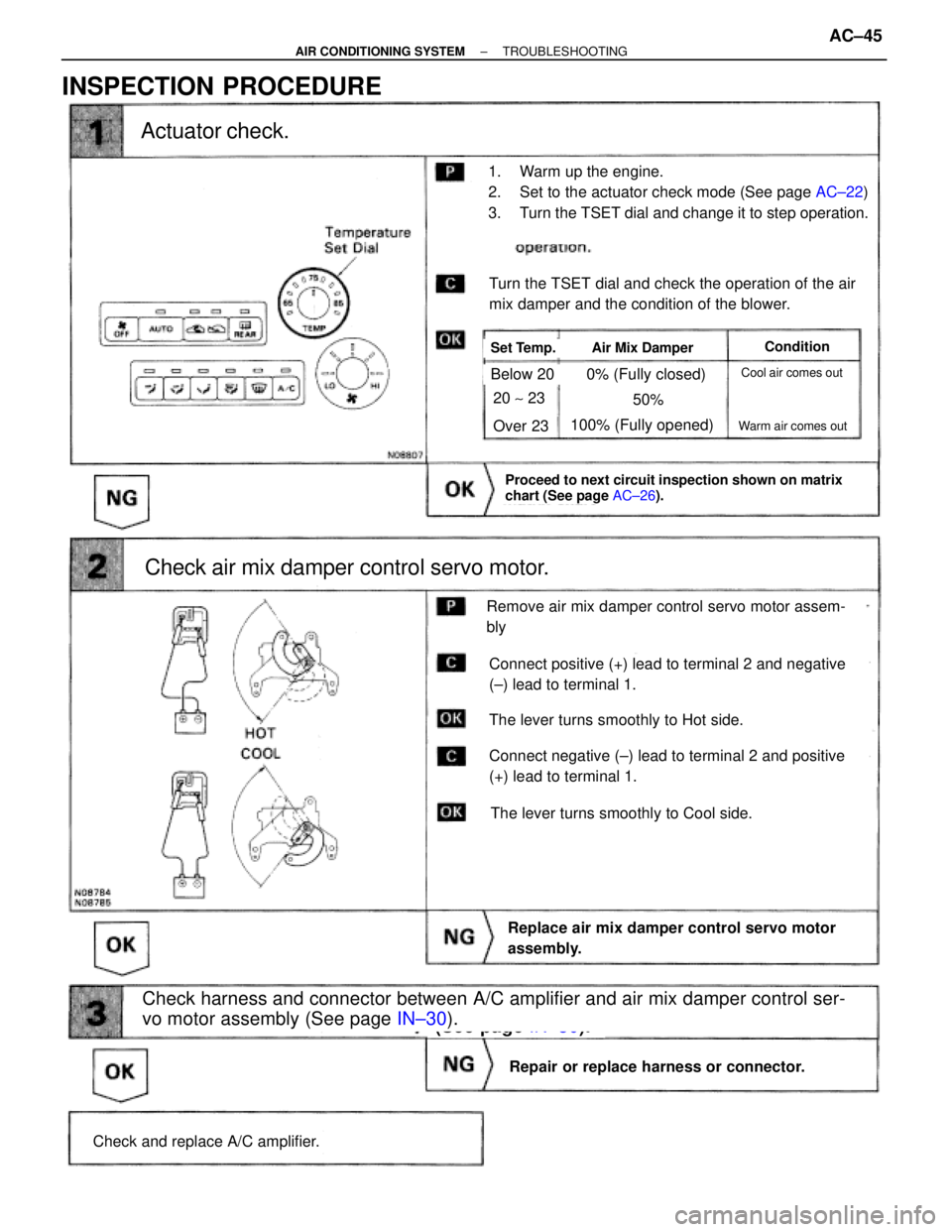
Actuator check.
Check and replace A/C amplifier.
Check harness and connector between A/C amplifier and air mix damper control ser-
vo motor assembly (See page IN±30).
Repair or replace harness or connector.
Replace air mix damper control servo motor
assembly.
Check air mix damper control servo motor.
Proceed to next circuit inspection shown on matrix
chart (See page AC±26).
Remove air mix damper control servo motor assem-
bly
The lever turns smoothly to Cool side.
The lever turns smoothly to Hot side.
Turn the TSET dial and check the operation of the air
mix damper and the condition of the blower.
Set Temp.Air Mix DamperCondition
Connect negative (±) lead to terminal 2 and positive
(+) lead to terminal 1.
Connect positive (+) lead to terminal 2 and negative
(±) lead to terminal 1.
1. Warm up the engine.
2. Set to the actuator check mode (See page AC±22)
3. Turn the TSET dial and change it to step operation.
Cool air comes out
Warm air comes out
0% (Fully closed)
100% (Fully opened)
Below 20
Over 23
20 ~ 2350%
INSPECTION PROCEDURE
± AIR CONDITIONING SYSTEMTROUBLESHOOTINGAC±45
Page 63 of 2543
Check voltage between terminal A/C IN of A/C amplifier connector and
body ground.
Check air conditioning compressor magnetic clutch.
Go to step
Check for open and short in harness and connector between air
conditioner compressor and magnetic clutch relay (See page IN±30).
Repair or replace harness or connector.
Go to step
1. Remove A/C amplifier with connectors still con
nected.
2. Start the engine.
Check voltage between terminal A/C IN of A/C amplifi-
er connector and body ground when magnetic clutch is
on and off by A/C switch.
Magnetic ClutchVoltage
ON
OFF Below 1 V
Connect positive (+) lead connected to battery to
magnetic clutch connector terminal 4.
Disconnect magnetic clutch connector.
Magnetic clutch is energized.
Repair air conditioning compressor magnetic
clutch.
10 ± 14 V
INSPECTION PROCEDURE
± AIR CONDITIONING SYSTEMTROUBLESHOOTINGAC±63
Page 64 of 2543
Go to step
Check and replace ECM.
Check voltage between terminal A/C of ECM and body ground.
Check voltage between terminal MGC of A/C amplifier connector and
body ground.
Magnetic ClutchVoltage
ON
OFF
Below 1 V
4 ± 6 V
1. Remove A/C amplifier with connectors still con
nected.
2. Start the engine.
Check voltage between terminal A/C IN of A/C amplifi-
er connector and body ground when magnetic clutch is
on and off by A/C switch.
1. Remove the ECM with connectors still con
nected.
2. Turn ignition switch on.
Magnetic ClutchVoltage
ON
OFF
Below 1 V
10 ± 14 V
Check and replace A/C amplifier.
Repair or replace harness or connector.
Check for open and short in harness and connector between A/C am-
plifier and ECM (See page IN±30).
1. Push the A/C switch on.
2. Measure voltage between terminal A/C of the
ECM connector and body ground.
AC±64± AIR CONDITIONING SYSTEMTROUBLESHOOTING
Page 71 of 2543
REFRIGERANT SYSTEM INSPECTION WITH MANIFOLD GAUGE SET
This is a method in which the trouble is located by using a manifold gauge set.
(See ªUSE OF MANIFOLD GAUGE SETº on page AC±11)
Read the manifold gauge pressure when the following conditions are established:
(a) Temperature at the air inlet with the switch set at RECIRC is 30±35 °C (86±95 °F)
(b) Engine running at 1,500 rpm
(c) Blower speed control switch set at high
(d) Temperature control set at max. cool
HINT: It should be noted that the gauge indications may vary slightly due to ambient temperature condi-
tions.
1. NORMALLY FUNCTIONING REFRIGERATION SYSTEM
Gauge reading:
Low pressure side:
0.15±0.25 MPa (1.5±2.5 kgf/cm
2)
High pressure side:
1.37±1.57 MPa (14±16 kgf/cm
2)
± AIR CONDITIONING SYSTEMTROUBLESHOOTINGAC±71
Page 74 of 2543
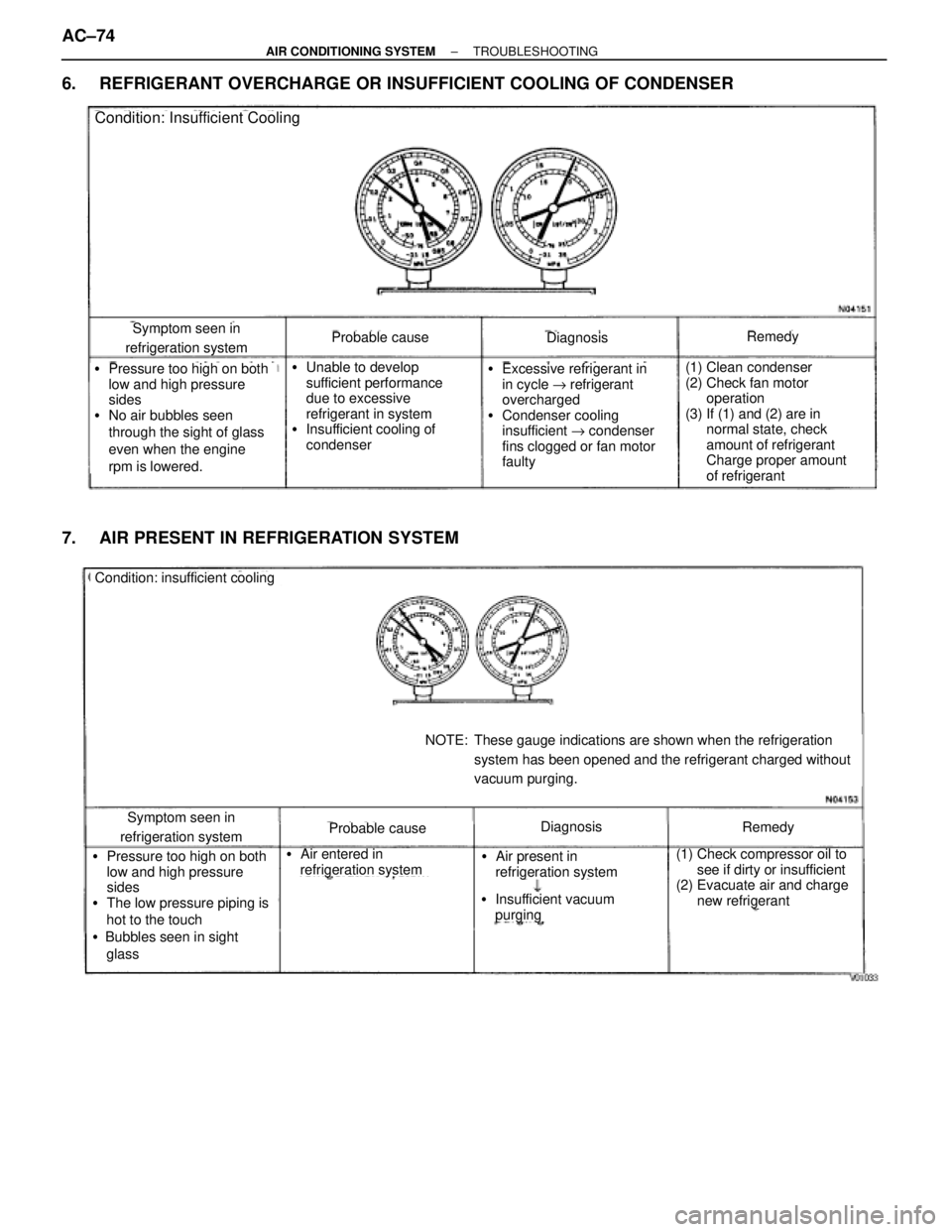
6. REFRIGERANT OVERCHARGE OR INSUFFICIENT COOLING OF CONDENSER
Symptom seen in
refrigeration systemProbable causeDiagnosisRemedy
(1) Clean condenser
(2) Check fan motor
operation
(3) If (1) and (2) are in
normal state, check
amount of refrigerant
Charge proper amount
of refrigerant�Pressure too high on both
low and high pressure
sides
�No air bubbles seen
through the sight of glass
even when the engine
rpm is lowered.�Unable to develop
sufficient performance
due to excessive
refrigerant in system
�Insufficient cooling of
condenser�Excessive refrigerant in
in cycle " refrigerant
overcharged
�Condenser cooling
insufficient " condenser
fins clogged or fan motor
faulty
Condition: Insufficient Cooling
7. AIR PRESENT IN REFRIGERATION SYSTEM
Condition: insufficient cooling
Symptom seen in
refrigeration systemProbable causeDiagnosisRemedy
(1) Check compressor oil to
see if dirty or insufficient
(2) Evacuate air and charge
new refrigerant�Pressure too high on both
low and high pressure
sides
�The low pressure piping is
hot to the touch
�Bubbles seen in sight
glass�Air entered in
refrigeration system�Air present in
refrigeration system
NOTE: These gauge indications are shown when the refrigeration
system has been opened and the refrigerant charged without
vacuum purging.
�Insufficient vacuum
purging
AC±74± AIR CONDITIONING SYSTEMTROUBLESHOOTING
Page 76 of 2543
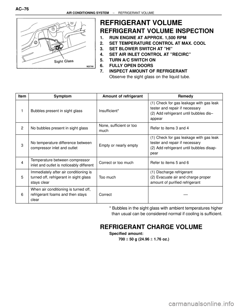
REFRIGERANT VOLUME
REFRIGERANT VOLUME INSPECTION
1. RUN ENGINE AT APPROX. 1,500 RPM
2. SET TEMPERATURE CONTROL AT MAX. COOL
3. SET BLOWER SWITCH AT ºHIº
4. SET AIR INLET CONTROL AT ºRECIRCº
5. TURN A/C SWITCH ON
6. FULLY OPEN DOORS
7. INSPECT AMOUNT OF REFRIGERANT
Observe the sight glass on the liquid tube.
��� ���Item������������� �������������Symptom��������� ���������Amount of refrigerant�������������� ��������������Remedy
��� �
�� �
�� �
�� ���
1
������������� �
������������ �
������������ �
������������ �������������
Bubbles present in sight glass
��������� �
�������� �
�������� �
�������� ���������
Insufficient*
�������������� �
������������� �
������������� �
������������� ��������������
(1) Check for gas leakage with gas leak
tester and repair if necessary
(2) Add refrigerant until bubbles dis±
appear
��� �
�� ���2
������������� �
������������ �������������No bubbles present in sight glass
��������� �
�������� ���������
None, sufficient or too
much�������������� �
������������� ��������������Refer to items 3 and 4
��� �
�� �
�� �
�� ���
3
������������� �
������������ �
������������ �
������������ �������������
No temperature difference between
compressor inlet and outlet
��������� �
�������� �
�������� �
�������� ���������
Empty or nearly empty
�������������� �
������������� �
������������� �
������������� ��������������
(1) Check for gas leakage with gas leak
tester and repair if necessary
(2) Add refrigerant until bubbles disap-
pear
��� �
�� ���4������������� �
������������ �������������
Temperature between compressor
inlet and outlet is noticeably different��������� �
�������� ���������Correct or too much�������������� �
������������� ��������������Refer to items 5 and 6
��� �
�� �
�� ���
5
������������� �
������������ �
������������ �������������
Immediately after air conditioning is
turned off, refrigerant in sight glass
stays clear��������� �
�������� �
�������� ���������
Too much
�������������� �
������������� �
������������� ��������������
(1) Discharge refrigerant
(2) Evacuate air and charge proper
amount of purified refrigerant
��� �
�� �
�� ���
6
������������� �
������������ �
������������ �������������
When air conditioning is turned off,
refrigerant foams and then stays
clear��������� �
�������� �
�������� ���������
Correct
�������������� �
������������� �
������������� ��������������
±±
* Bubbles in the sight glass with ambient temperatures higher
than usual can be considered normal if cooling is sufficient.
REFRIGERANT CHARGE VOLUME
Specified amount:
700 + 50 g (24.96 + 1.76 oz.)
AC±76± AIR CONDITIONING SYSTEMREFRIGERANT VOLUME
Page 77 of 2543
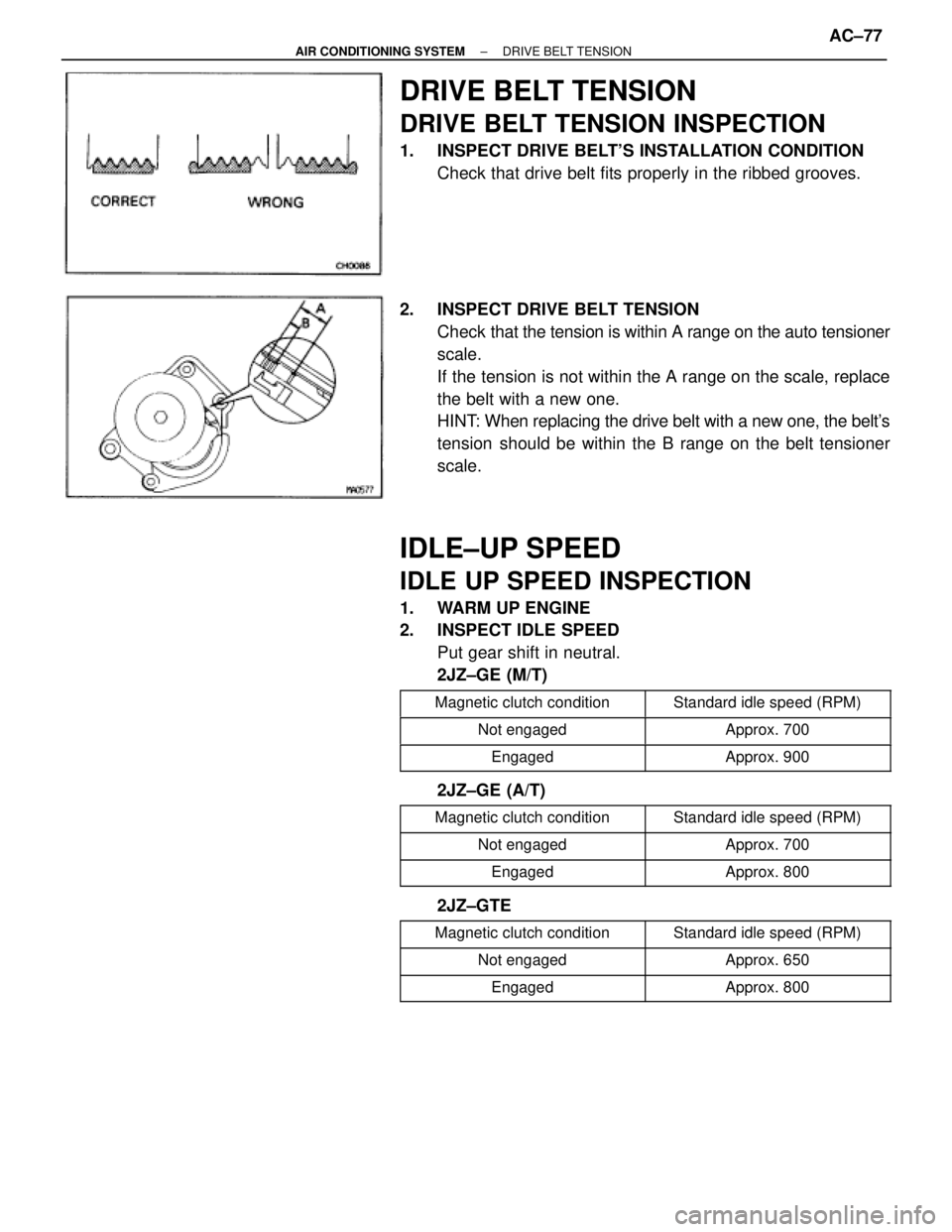
DRIVE BELT TENSION
DRIVE BELT TENSION INSPECTION
1. INSPECT DRIVE BELT'S INSTALLATION CONDITION
Check that drive belt fits properly in the ribbed grooves.
2. INSPECT DRIVE BELT TENSION
Check that the tension is within A range on the auto tensioner
scale.
If the tension is not within the A range on the scale, replace
the belt with a new one.
HINT: When replacing the drive belt with a new one, the belt's
tension should be within the B range on the belt tensioner
scale.
IDLE±UP SPEED
IDLE UP SPEED INSPECTION
1. WARM UP ENGINE
2. INSPECT IDLE SPEED
Put gear shift in neutral.
2JZ±GE (M/T)
����������� �
����������Magnetic clutch condition������������ �
�����������Standard idle speed (RPM)
����������� �����������Not engaged������������ ������������Approx. 700
����������� �����������Engaged������������ ������������Approx. 900
2JZ±GE (A/T)
����������� �����������Magnetic clutch condition������������ ������������Standard idle speed (RPM)����������� �����������Not engaged������������ ������������Approx. 700����������� �
���������� �����������Engaged
������������ �
����������� ������������Approx. 800
2JZ±GTE
����������� �����������Magnetic clutch condition������������ ������������Standard idle speed (RPM)
����������� �����������Not engaged������������ ������������Approx. 650����������� �����������Engaged������������ ������������Approx. 800
± AIR CONDITIONING SYSTEMDRIVE BELT TENSIONAC±77
Page 80 of 2543
AIR CONDITIONING UNIT
AIR CONDITIONING UNIT REMOVAL
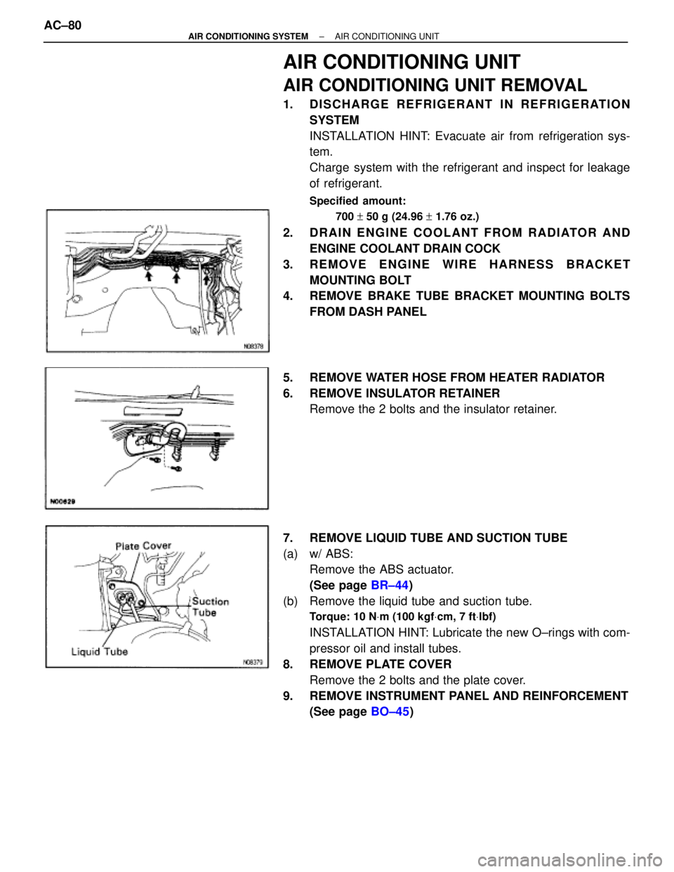
1. DISCHARGE REFRIGERANT IN REFRIGERATION
SYSTEM
INSTALLATION HINT: Evacuate air from refrigeration sys-
tem.
Charge system with the refrigerant and inspect for leakage
of refrigerant.
Specified amount:
700 + 50 g (24.96 + 1.76 oz.)
2. DRAIN ENGINE COOLANT FROM RADIATOR AND
ENGINE COOLANT DRAIN COCK
3. REMOVE ENGINE WIRE HARNESS BRACKET
MOUNTING BOLT
4. REMOVE BRAKE TUBE BRACKET MOUNTING BOLTS
FROM DASH PANEL
5. REMOVE WATER HOSE FROM HEATER RADIATOR
6. REMOVE INSULATOR RETAINER
Remove the 2 bolts and the insulator retainer.
7. REMOVE LIQUID TUBE AND SUCTION TUBE
(a) w/ ABS:
Remove the ABS actuator.
(See page BR±44)
(b) Remove the liquid tube and suction tube.
Torque: 10 NVm (100 kgfVcm, 7 ftVlbf)
INSTALLATION HINT: Lubricate the new O±rings with com-
pressor oil and install tubes.
8. REMOVE PLATE COVER
Remove the 2 bolts and the plate cover.
9. REMOVE INSTRUMENT PANEL AND REINFORCEMENT
(See page BO±45) AC±80
± AIR CONDITIONING SYSTEMAIR CONDITIONING UNIT