Page 1551 of 2543

IF VEHICLE IS EQUIPPED WITH MOBILE
RADIO SYSTEM (HAM, CB, ETC.)
If the vehicle is equipped with a mobile communication sys-
tem, refer to the precaution in the IN section.
AIR INDUCTION SYSTEM
1. Separation of the engine oil dipstick, oil filler cap, PCV hose,
etc. may cause the engine to run out of tune.
2. Disconnection, looseness or cracks in the parts of the air
induction system between the throttle body and cylinder
head will cause air suction and cause the engine to run out
of tune.
ELECTRONIC CONTROL SYSTEM
1. Before removing SFI wiring connectors, terminals, etc., first
disconnect the power by either turning the ignition switch
OFF or disconnecting the negative (±) terminal cable from the
battery.
HINT: Always check the diagnostic trouble code before dis-
connecting the negative (±) terminal cable from the battery.
2. When installing the battery, be especially careful not to
incorrectly connect the positive (+) and negative (±) cables.
3. Do not permit parts to receive a severe impact during removal
or installation. Handle all SFI parts carefully, especially the
ECM.
4. Do not be careless during troubleshooting as there are
numerous transistor circuits and even slight terminal contact
can cause further troubles.
5. Do not open the ECM cover.
6. When inspecting during rainy weather, take care to prevent
entry of water. Also, when washing the engine compartment,
prevent water from getting on the SFI parts and wiring
connectors.
7. Parts should be replaced as an assembly.
8. Care is required when pulling out and inserting wiring
connectors.
(a) Release the lock and pull out the connector, pulling on the
connectors.
(b) Fully insert the connector and check that it is locked.
± ENGINESFI SYSTEM (2JZ±GTE)EG±261
Page 1731 of 2543

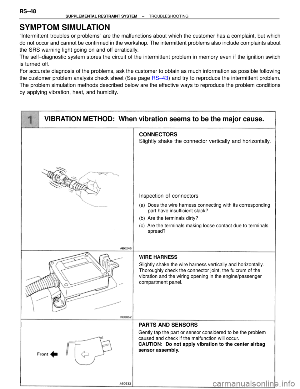
CONNECTORS
Slightly shake the connector vertically and horizontally.
Inspection of connectors
(a) Does the wire harness connecting with its corresponding
part have insufficient slack?
(b) Are the terminals dirty?
(c) Are the terminals making loose contact due to terminals
spread?
WIRE HARNESS
Slightly shake the wire harness vertically and horizontally.
Thoroughly check the connector joint, the fulcrum of the
vibration and the wiring opening in the engine/passenger
compartment panel.
PARTS AND SENSORS
Gently tap the part or sensor considered to be the problem
caused and check if the malfunction will occur.
CAUTION: Do not apply vibration to the center airbag
sensor assembly.
VIBRATION METHOD: When vibration seems to be the major cause.
SYMPTOM SIMULATION
ªIntermittent troubles or problemsº are the malfunctions about which the customer has a complaint, but which
do not occur and cannot be confirmed in the workshop. The intermittent problems also include complaints about
the SRS warning light going on and off erratically.
The self±diagnostic system stores the circuit of the intermittent problem in memory even if the ignition switch
is turned off.
For accurate diagnosis of the problems, ask the customer to obtain as much information as possible following
the customer problem analysis check sheet (See page RS±43) and try to reproduce the intermittent problem.
The problem simulation methods described below are the effective ways to reproduce the problem conditions
by applying vibration, heat, and humidity. RS±48
± SUPPLEMENTAL RESTRAINT SYSTEMTROUBLESHOOTING
Page 1949 of 2543

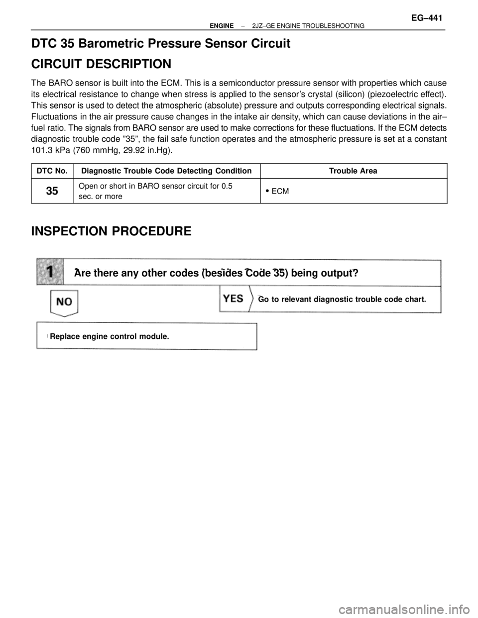
DTC 35 Barometric Pressure Sensor Circuit
CIRCUIT DESCRIPTION
The BARO sensor is built into the ECM. This is a semiconductor pressure sensor with properties which cause
its electrical resistance to change when stress is applied to the sensor's crystal (silicon) (piezoelectric effect).
This sensor is used to detect the atmospheric (absolute) pressure and outputs corresponding electrical signals.
Fluctuations in the air pressure cause changes in the intake air density, which can cause deviations in the air±
fuel ratio. The signals from BARO sensor are used to make corrections for these fluctuations. If the ECM detects
diagnostic trouble code º35º, the fail safe function operates and the atmospheric pressure is set at a constant
101.3 kPa (760 mmHg, 29.92 in.Hg).
����� �����DTC No.���������������� ����������������Diagnostic Trouble Code Detecting Condition����������������� �����������������Trouble Area����� �����
35
���������������� ����������������
Open or short in BARO sensor circuit for 0.5
����������������� �����������������
�ECM����� �����35���������������� ���������������� Oen or short in BARO sensor circuit for 0.5
sec. or more����������������� ����������������� � ECM
INSPECTION PROCEDURE
Are there any other codes (besides Code 35) being output?
Go to relevant diagnostic trouble code chart.
Replace engine control module.
± ENGINE2JZ±GE ENGINE TROUBLESHOOTINGEG±441
Page 1986 of 2543
VSV Circuit for ACIS
CIRCUIT DESCRIPTION
The circuit opens and closes the IACV (Intake Air Control Valve) in response to the engine load in order
to increase the intake efficiency (ACIS: Acoustic Control Induction System).
When the engine speed is 4,500 rpm or less and throttle valve opening angle is 30° or more, or engine
speed is 4,500 rpm or more and throttle valve opening angle is 30° or less, the engine control module
turns the VSV ON and closes the IACV. At all other times, the VSV is OFF, so the IACV is open.
VSVIACV
ON
OFF
closed
open
EG±478± ENGINE2JZ±GE ENGINE TROUBLESHOOTING
Page 2136 of 2543

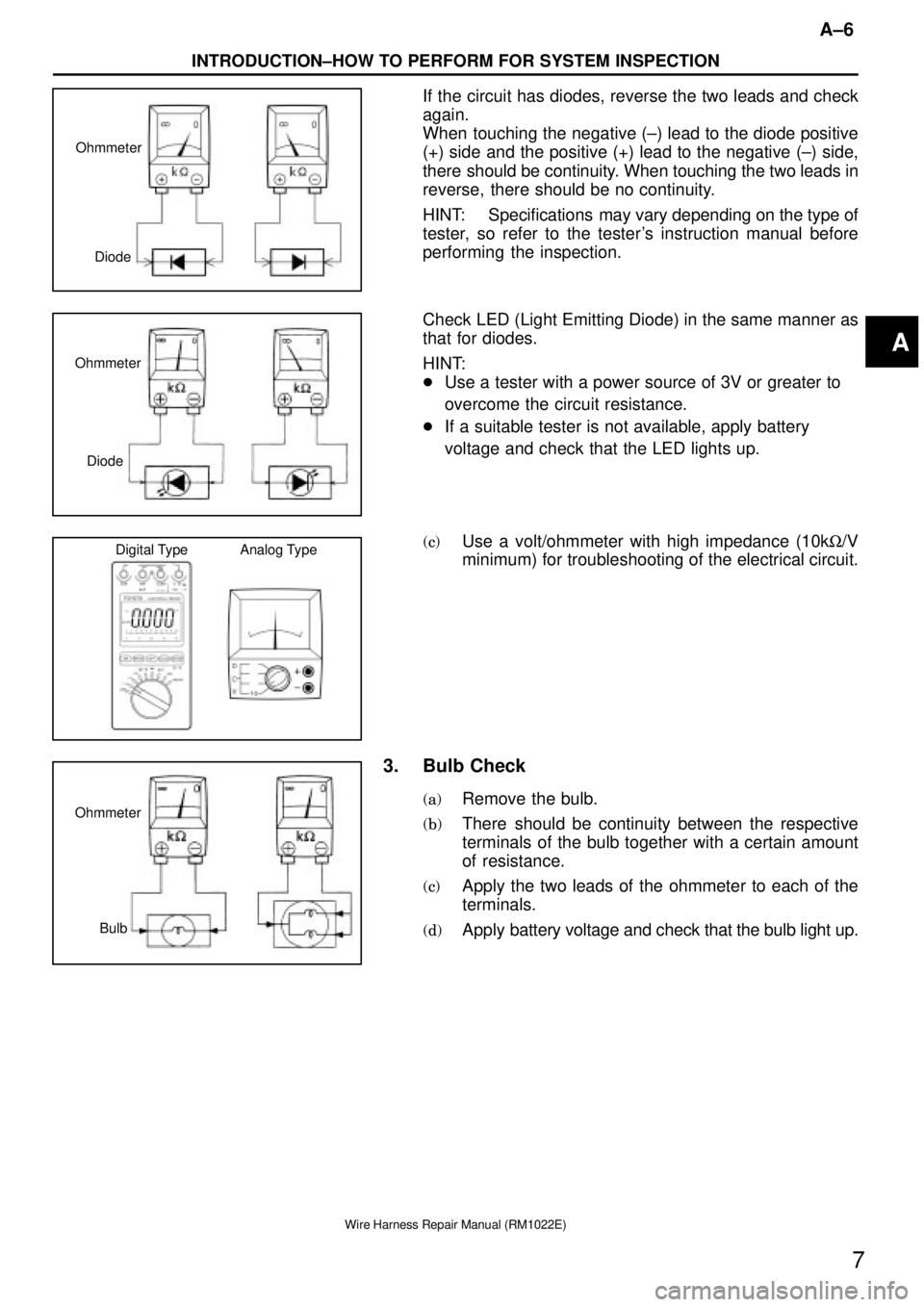
Diode Ohmmeter
Diode Ohmmeter
Digital Type Analog Type
Bulb Ohmmeter
A±6
INTRODUCTION±HOW TO PERFORM FOR SYSTEM INSPECTION
7
Wire Harness Repair Manual (RM1022E)
If the circuit has diodes, reverse the two leads and check
again.
When touching the negative (±) lead to the diode positive
(+) side and the positive (+) lead to the negative (±) side,
there should be continuity. When touching the two leads in
reverse, there should be no continuity.
HINT: Specifications may vary depending on the type of
tester, so refer to the tester's instruction manual before
performing the inspection.
Check LED (Light Emitting Diode) in the same manner as
that for diodes.
HINT:
�Use a tester with a power source of 3V or greater to
overcome the circuit resistance.
�If a suitable tester is not available, apply battery
voltage and check that the LED lights up.
(c)Use a volt/ohmmeter with high impedance (10kW/V
minimum) for troubleshooting of the electrical circuit.
3. Bulb Check
(a)Remove the bulb.
(b)There should be continuity between the respective
terminals of the bulb together with a certain amount
of resistance.
(c)Apply the two leads of the ohmmeter to each of the
terminals.
(d)Apply battery voltage and check that the bulb light up.
A
Page 2143 of 2543

TERMINAL AND CONNECTOR REPAIR±TERMINAL REPLACEMENT
B±4
14
Wire Harness Repair Manual (RM1022E)
Step 1. Identify the connector and the terminal type.
Confirm whether the connector you require is the non±waterproof, waterproof or combined terminal type
connector from the pictures provided in the following charts.
Connector
Description
Non±Waterproof TypeThose connectors which are not of the
waterproof or combined terminal type.
Waterproof TypeWaterproof material (hole plug or terminal
packing) is provided on the terminal/connector
body.
Combined Terminal TypeTerminals of different shape/size are located in
one connector.
1. Terminal with Wire
Identify the part number of the terminal with wire by picking
out the corresponding illustration from the pictures
provided on the following charts.
HINT: In some of the illustrations, there are two part
numbers for the same illustration of terminal with wire,
because although the shapes of the terminals are
completely the same, there is a difference in with /without
gold±plating (gilded).
Remark: T h e length of the wire connected to the
terminal is approximately 150 mm.
B
Page 2144 of 2543

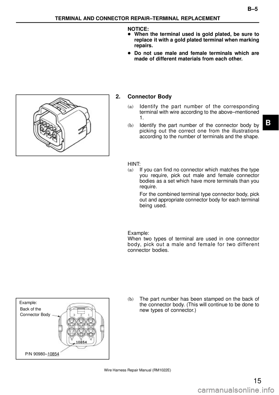
Example:
Back of the
Connector Body
P/N 90980±10854
B±5
TERMINAL AND CONNECTOR REPAIR±TERMINAL REPLACEMENT
15
Wire Harness Repair Manual (RM1022E)
NOTICE:
�When the terminal used is gold plated, be sure to
replace it with a gold plated terminal when marking
repairs.
�Do not use male and female terminals which are
made of different materials from each other.
2. Connector Body
(a)Identify the part number of the corresponding
terminal with wire according to the above±mentioned
1.
(b)Identify the part number of the connector body by
picking out the correct one from the illustrations
according to the number of terminals and the shape.
HINT:
(a)If you can find no connector which matches the type
you require, pick out male and female connector
bodies as a set which have more terminals than you
require.
For the combined terminal type connector body, pick
out and appropriate connector body for each terminal
being used.
Example:
When two types of terminal are used in one connector
body, pick out a male and female for two different
connector bodies.
(b)The part number has been stamped on the back of
the connector body. (This will continue to be done to
new types of connector.)
B
Page 2145 of 2543
Hole Plug
Connector Body
Terminal
Packing
Small (Red)
Large (Yellow) Medium (Blue)
Medium (Blue) 1.0±2.0 mm
Large (Yellow) 3.0±5.0 mmWire Outside
DiameterSleeve Size
(Color)
Small (Red) 0.2±1.0 mm
Wire Outside Diameter
Insulation Calipers
TERMINAL AND CONNECTOR REPAIR±TERMINAL REPLACEMENT
B±6
16
Wire Harness Repair Manual (RM1022E)
3. Hole Plug/Terminal Packing
(a)Identify the part number of the appropriate terminal
with wire/connector body from the illustrations of
waterproof type connector according to the
above±mentioned 1 and 2.
(b)Identify the part number of the hole plug/terminal
packing from the corresponding illustration.
4. Sleeve
When connecting two wires using a sleeve, select the
sleeve according to the following table.
(a)When size is based on the outside diameter of the
wire.
B