Page 1176 of 2543
FOR VEHICLES WITH DATA LINK
CONNECTOR 2 (DLC2)
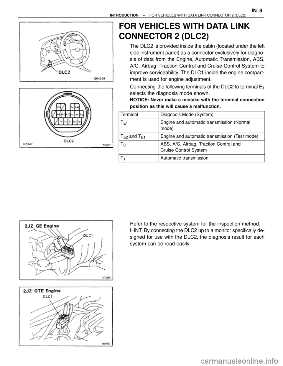
The DLC2 is provided inside the cabin (located under the left
side instrument panel) as a connector exclusively for diagno-
sis of data from the Engine, Automatic Transmission, ABS,
A/C, Airbag, Traction Control and Cruise Control System to
improve serviceability. The DLC1 inside the engine compart-
ment is used for engine adjustment.
Connecting the following terminals of the DLC2 to terminal E
1
selects the diagnosis mode shown.
NOTICE: Never make a mistake with the terminal connection
position as this will cause a malfunction.
������� �������Terminal���������������� ����������������Diagnosis Mode (System)
������� �
������ �������TE1���������������� �
��������������� ����������������Engine and automatic transmission (Normal
mode)
������� �������TE2 and TE1���������������� ����������������Engine and automatic transmission (Test mode)������� �
������ �������TC���������������� �
��������������� ����������������ABS, A/C, Airbag, Traction Control and
Cruise Control System
������� �������TT���������������� ����������������Automatic transmission
Refer to the respective system for the inspection method.
HINT: By connecting the DLC2 up to a monitor specifically de-
signed for use with the DLC2, the diagnosis result for each
system can be read easily.
± INTRODUCTIONFOR VEHICLES WITH DATA LINK CONNECTOR 2 (DLC2)IN±9
Page 1193 of 2543
[4] DIAGNOSTIC TROUBLE CODE CHART
The inspection procedure is shown in the table below. This table permits efficient and accurate troubleshooting
using the diagnostic trouble codes displayed in the diagnostic trouble code check. Proceed with troubleshooting
in accordance with the inspection procedure given in the diagnostic chart corresponding to the diagnostic
trouble codes displayed. The engine diagnostic trouble code chart is shown below as an example.
IN±26± INTRODUCTIONHOW TO TROUBLESHOOT ECU CONTROLLED SYSTEMS
Page 1249 of 2543
22. TIGHTEN BOLTS AND NUTS ON CHASSIS AND BODY
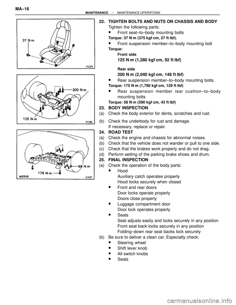
Tighten the following parts:
wFront seat±to±body mounting bolts
Torque: 37 NVm (375 kgfVcm, 27 ftVlbf).
wFront suspension member±to±body mounting bolt
Torque:
Front side
125 NVm (1,280 kgfVcm, 92 ftVlbf)
Rear side
200 NVm (2,040 kgfVcm, 148 ftVlbf)
wRear suspension member±to±body mounting bolts.
Torque: 175 NVm (1,790 kgfVcm, 129 ftVlbf)
wRear suspension member rear cushion±to±body
mounting bolts
Torque: 58 NVm (590 kgfVcm, 43 ftVlbf)
23. BODY INSPECTION
(a) Check the body exterior for dents, scratches and rust.
(b) Check the underbody for rust and damage.
If necessary, replace or repair.
24. ROAD TEST
(a) Check the engine and chassis for abnormal noises.
(b) Check that the vehicle does not wander or pull to one side.
(c) Check that the brakes work properly and do not drag.
(d) Perform setting of the parking brake shoes and drum.
25. FINAL INSPECTION
(a) Check the operation of the body parts:
wHood
Auxiliary catch operates properly
Hood locks securely when closed
wFront and rear doors
Door locks operate properly
Doors close properly
wLuggage compartment door
Door lock operates properly
wSeats
Seat adjusts easily and locks securely in any position
Front seat back locks securely in any position
Folding±down rear seat backs lock securely
(b) Be sure to deliver a clean car. Especially check:
wSteering wheel
wShift lever knob
wAll switch knobs
wSeats MA±16
± MAINTENANCEMAINTENANCE OPERATIONS
Page 1468 of 2543
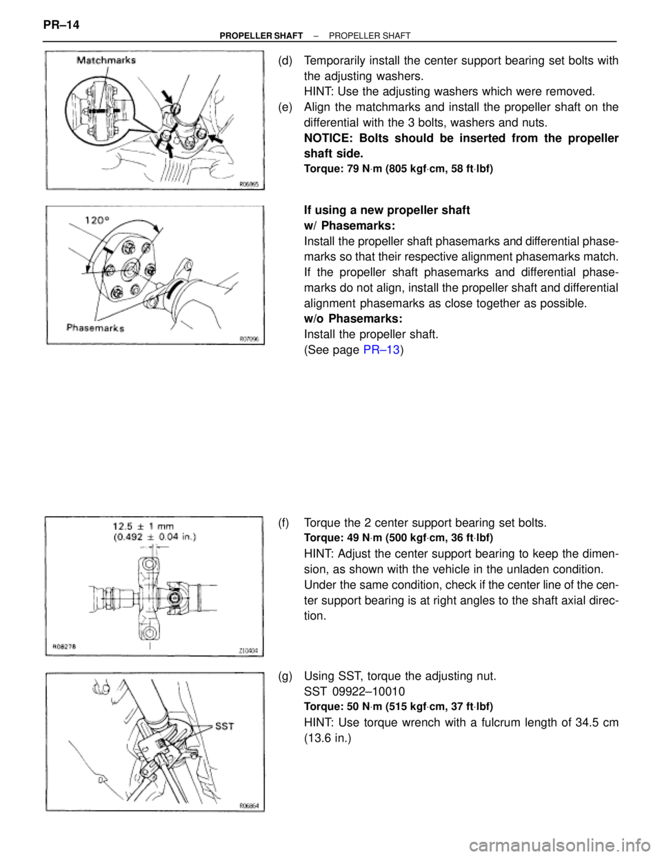
(d) Temporarily install the center support bearing set bolts with
the adjusting washers.
HINT: Use the adjusting washers which were removed.
(e) Align the matchmarks and install the propeller shaft on the
differential with the 3 bolts, washers and nuts.
NOTICE: Bolts should be inserted from the propeller
shaft side.
Torque: 79 NVm (805 kgfVcm, 58 ftVlbf)
If using a new propeller shaft
w/ Phasemarks:
Install the propeller shaft phasemarks and differential phase-
marks so that their respective alignment phasemarks match.
If the propeller shaft phasemarks and differential phase-
marks do not align, install the propeller shaft and differential
alignment phasemarks as close together as possible.
w/o Phasemarks:
Install the propeller shaft.
(See page PR±13)
(f) Torque the 2 center support bearing set bolts.
Torque: 49 NVm (500 kgfVcm, 36 ftVlbf)
HINT: Adjust the center support bearing to keep the dimen-
sion, as shown with the vehicle in the unladen condition.
Under the same condition, check if the center line of the cen-
ter support bearing is at right angles to the shaft axial direc-
tion.
(g) Using SST, torque the adjusting nut.
SST 09922±10010
Torque: 50 NVm (515 kgfVcm, 37 ftVlbf)
HINT: Use torque wrench with a fulcrum length of 34.5 cm
(13.6 in.) PR±14
± PROPELLER SHAFTPROPELLER SHAFT
Page 1469 of 2543
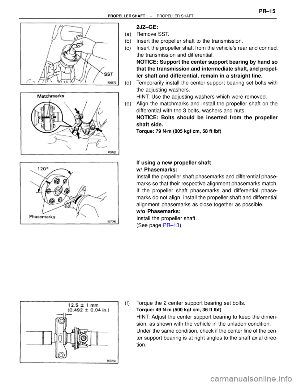
2JZ±GE:
(a) Remove SST.
(b) Insert the propeller shaft to the transmission.
(c) Insert the propeller shaft from the vehicle's rear and connect
the transmission and differential.
NOTICE: Support the center support bearing by hand so
that the transmission and intermediate shaft, and propel-
ler shaft and differential, remain in a straight line.
(d) Temporarily install the center support bearing set bolts with
the adjusting washers.
HINT: Use the adjusting washers which were removed.
(e) Align the matchmarks and install the propeller shaft on the
differential with the 3 bolts, washers and nuts.
NOTICE: Bolts should be inserted from the propeller
shaft side.
Torque: 79 NVm (805 kgfVcm, 58 ftVlbf)
If using a new propeller shaft
w/ Phasemarks:
Install the propeller shaft phasemarks and differential phase-
marks so that their respective alignment phasemarks match.
If the propeller shaft phasemarks and differential phase-
marks do not align, install the propeller shaft and differential
alignment phasemarks as close together as possible.
w/o Phasemarks:
Install the propeller shaft.
(See page PR±13)
(f) Torque the 2 center support bearing set bolts.
Torque: 49 NVm (500 kgfVcm, 36 ftVlbf)
HINT: Adjust the center support bearing to keep the dimen-
sion, as shown with the vehicle in the unladen condition.
Under the same condition, check if the center line of the cen-
ter support bearing is at right angles to the shaft axial direc-
tion.
± PROPELLER SHAFTPROPELLER SHAFTPR±15
Page 1479 of 2543
PRECAUTION
1. Before working on the fuel system, disconnect the
negative (±) terminal cable from the battery.
HINT: Any diagnostic trouble code retained by the computer
will be erased when the negative (±) terminal cable is discon-
nected.
Therefore, if necessary, read the diagnosis before discon-
necting the negative (±) terminal cable from the battery.
2. Do not smoke or work near an open flame when working
on the fuel system.
3. Keep gasoline away from rubber or leather parts.
MAINTENANCE PRECAUTIONS
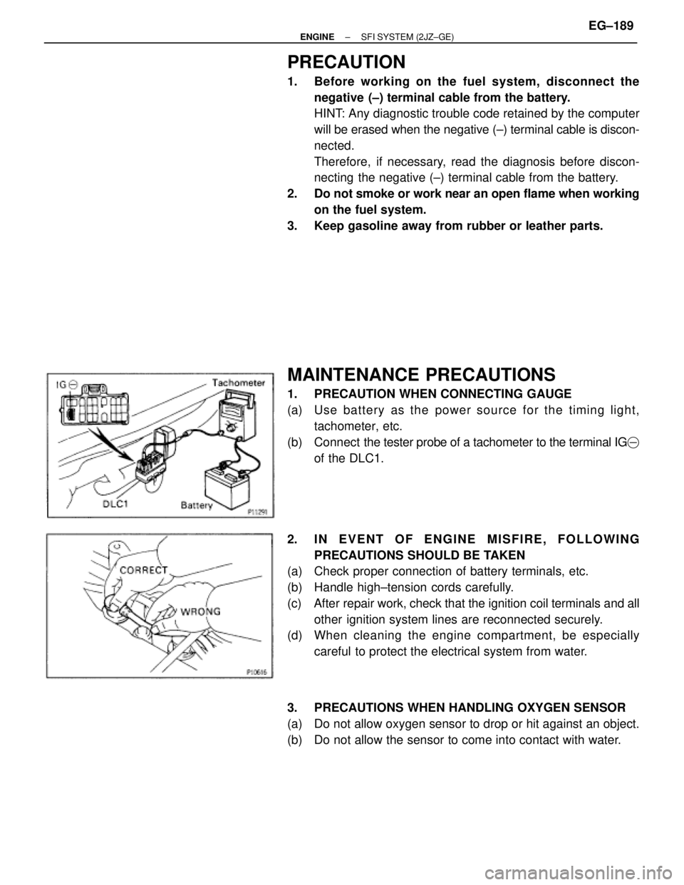
1. PRECAUTION WHEN CONNECTING GAUGE
(a) Use ba tte ry as th e po we r so u rce fo r th e timin g lig h t,
tachometer, etc.
(b) Connect the tester probe of a tachometer to the terminal IG�
of the DLC1.
2. IN EVENT OF ENGINE MISFIRE, FOLLOWING
PRECAUTIONS SHOULD BE TAKEN
(a) Check proper connection of battery terminals, etc.
(b) Handle high±tension cords carefully.
(c) After repair work, check that the ignition coil terminals and all
other ignition system lines are reconnected securely.
(d) When cleaning the engine compartment, be especially
careful to protect the electrical system from water.
3. PRECAUTIONS WHEN HANDLING OXYGEN SENSOR
(a) Do not allow oxygen sensor to drop or hit against an object.
(b) Do not allow the sensor to come into contact with water.
± ENGINESFI SYSTEM (2JZ±GE)EG±189
Page 1480 of 2543

IF VEHICLE IS EQUIPPED WITH MOBIL
RADIO SYSTEM (HAM, CB, ETC.)
If the vehicle is equipped with a mobile communication sys-
tem, refer to the precaution in the IN section.
AIR INDUCTION SYSTEM
1. Separation of the engine oil dipstick, oil filler cap, PCV hose,
etc. may cause the engine to run out of tune.
2. Disconnection, looseness or cracks in the parts of the air
induction system between the throttle body and cylinder
head will cause air suction and cause the engine to run out
of tune.
ELECTRONIC CONTROL SYSTEM
1. Before removing SFI wiring connectors, terminals, etc., first
disconnect the power by either turning the ignition switch
OFF or disconnecting the negative (±) terminal cable from the
battery.
HINT: Always check the diagnostic trouble code before dis-
connecting the negative (±) terminal cable from the battery.
2. When installing the battery, be especially careful not to
incorrectly connect the positive (+) and negative (±) cables.
3. Do not permit parts to receive a severe impact during removal
or installation. Handle all SFI parts carefully, especially the
ECM.
4. Do not be careless during troubleshooting as there are
numerous transistor circuits and even slight terminal contact
can cause further troubles.
5. Do not open the ECM cover.
6. When inspecting during rainy weather, take care to prevent
entry of water. Also, when washing the engine compartment,
prevent water from getting on the SFI parts and wiring
connectors.
7. Parts should be replaced as an assembly.
8. Care is required when pulling out and inserting wiring
connectors.
(a) Release the lock and pull out the connector, pulling on the
connectors.
(b) Fully insert the connector and check that it is locked. EG±190
± ENGINESFI SYSTEMS (2JZ±GE)
Page 1550 of 2543
PRECAUTION
1. Before working on the fuel system, disconnect the
negative (±) terminal cable from the battery.
HINT: Any diagnostic trouble code retained by the computer
will be erased when the negative (±) terminal cable is discon-
nected.
Therefore, if necessary, read the diagnosis before discon-
necting the negative (±) terminal cable from the battery.
2. Do not smoke or work near an open flame when working
on the fuel system.
3. Keep gasoline away from rubber or leather parts.
MAINTENANCE PRECAUTIONS
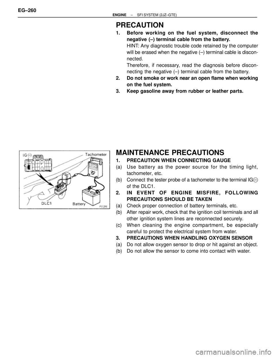
1. PRECAUTION WHEN CONNECTING GAUGE
(a) Use ba tte ry as th e po we r so u rce fo r th e timin g lig h t,
tachometer, etc.
(b) Connect the tester probe of a tachometer to the terminal IG�
of the DLC1.
2. IN EVENT OF ENGINE MISFIRE, FOLLOWING
PRECAUTIONS SHOULD BE TAKEN
(a) Check proper connection of battery terminals, etc.
(b) After repair work, check that the ignition coil terminals and all
other ignition system lines are reconnected securely.
(c) When cleaning the engine compartment, be especially
careful to protect the electrical system from water.
3. PRECAUTIONS WHEN HANDLING OXYGEN SENSOR
(a) Do not allow oxygen sensor to drop or hit against an object.
(b) Do not allow the sensor to come into contact with water. EG±260
± ENGINESFI SYSTEM (2JZ±GTE)