Page 471 of 2543
Pattern Select Switch Circuit
CIRCUIT DESCRIPTION
The ECM memory contains the shift programs for the NORMAL and MANUAL patterns, 2 position, and L posi-
tion and the lock±up patterns. Following the programs corresponding to the signals from the pattern select
switch, the park/neutral position switch and other various sensors the ECM switches the solenoid valves ON
and OFF, thereby controlling the transmission gear change and the lock±up clutch operation.
WIRING DIAGRAM
INSPECTION PROCEDURE
Check A/T fluid temp. sensor. (See page AT1±64).
Replace A/T fluid temp. sensor.
± AT340E (2JZ±GE) AUTOMATIC TRANSMISSIONTROUBLESHOOTINGAT1±85
Page 491 of 2543
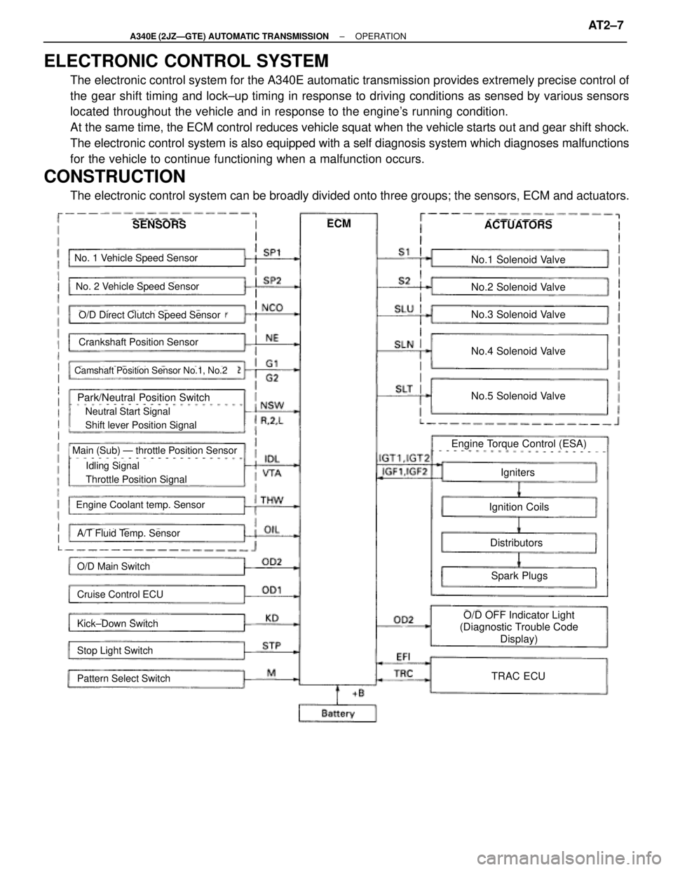
ELECTRONIC CONTROL SYSTEM
The electronic control system for the A340E automatic transmission provides extremely precise control of
the gear shift timing and lock±up timing in response to driving conditions as sensed by various sensors
located throughout the vehicle and in response to the engine's running condition.
At the same time, the ECM control reduces vehicle squat when the vehicle starts out and gear shift shock.
The electronic control system is also equipped with a self diagnosis system which diagnoses malfunctions
for the vehicle to continue functioning when a malfunction occurs.
CONSTRUCTION
The electronic control system can be broadly divided onto three groups; the sensors, ECM and actuators.
No. 1 Vehicle Speed Sensor
No. 2 Vehicle Speed Sensor
Crankshaft Position Sensor
Camshaft Position Sensor No.1, No.2
Park/Neutral Position Switch
� Neutral Start Signal
� Shift lever Position Signal
� Idling Signal
� Throttle Position Signal
Main (Sub) Ð throttle Position Sensor
Engine Coolant temp. Sensor
A/T Fluid Temp. Sensor
O/D Main Switch
Cruise Control ECU
Kick±Down Switch
Stop Light Switch
Pattern Select Switch
SENSORSECMACTUATORS
No.1 Solenoid Valve
No.2 Solenoid Valve
No.3 Solenoid Valve
No.4 Solenoid Valve
No.5 Solenoid Valve
Engine Torque Control (ESA)
Igniters
Ignition Coils
Distributors
Spark Plugs
O/D OFF Indicator Light
(Diagnostic Trouble Code
Display)
TRAC ECU
O/D Direct Clutch Speed Sensor
± A340E (2JZÐGTE) AUTOMATIC TRANSMISSIONOPERATIONAT2±7
Page 537 of 2543
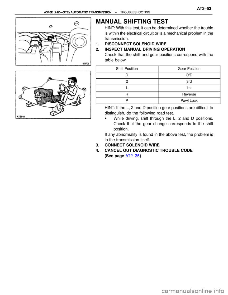
MANUAL SHIFTING TEST
HINT: With this test, it can be determined whether the trouble
is within the electrical circuit or is a mechanical problem in the
transmission.
1. DISCONNECT SOLENOID WIRE
2. INSPECT MANUAL DRIVING OPERATION
Check that the shift and gear positions correspond with the
table below.
������������ ������������Shift Position������������ ������������Gear Position
������������ ������������D������������ ������������O/D
������������ ������������2������������ ������������3rd������������ ������������L������������ ������������1st������������ �
����������� ������������R
������������ �
����������� ������������Reverse
������������ ������������P������������ ������������Pawl Lock
HINT: If the L, 2 and D position gear positions are difficult to
distinguish, do the following road test.
wWhile driving, shift through the L, 2 and D positions.
Check that the gear change corresponds to the shift
position.
If any abnormality is found in the above test, the problem is
in the transmission itself.
3. CONNECT SOLENOID WIRE
4. CANCEL OUT DIAGNOSTIC TROUBLE CODE
(See page AT2±35)
± A340E (2JZÐGTE) AUTOMATIC TRANSMISSIONTROUBLESHOOTINGAT2±53
Page 542 of 2543
*1: ºOº mark means ºO/D OFFº light blinks once every 2 seconds.
ºXº mark means ºO/D OFFº light never blinks.
*2: ºOº marks means the ECM memorizes the malfunction code if the ECM detects the diagnostic trouble code
detection condition.
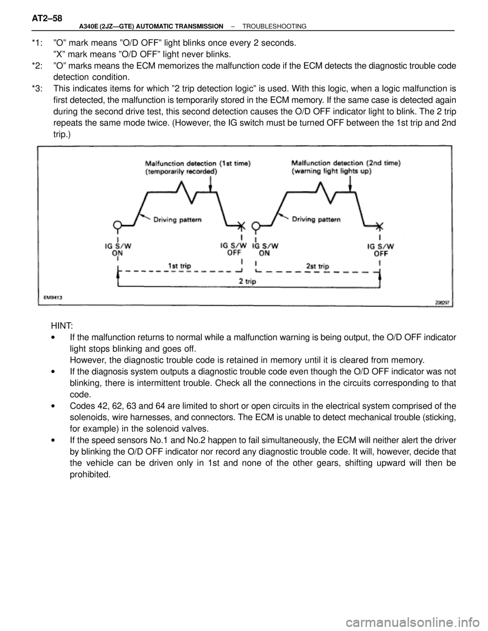
*3: This indicates items for which º2 trip detection logicº is used. With this logic, when a logic malfunction is
first detected, the malfunction is temporarily stored in the ECM memory. If the same case is detected again
during the second drive test, this second detection causes the O/D OFF indicator light to blink. The 2 trip
repeats the same mode twice. (However, the IG switch must be turned OFF between the 1st trip and 2nd
trip.)
HINT:
wIf the malfunction returns to normal while a malfunction warning is being output, the O/D OFF indicator
light stops blinking and goes off.
However, the diagnostic trouble code is retained in memory until it is cleared from memory.
wIf the diagnosis system outputs a diagnostic trouble code even though the O/D OFF indicator was not
blinking, there is intermittent trouble. Check all the connections in the circuits corresponding to that
code.
wCodes 42, 62, 63 and 64 are limited to short or open circuits in the electrical system comprised of the
solenoids, wire harnesses, and connectors. The ECM is unable to detect mechanical trouble (sticking,
for example) in the solenoid valves.
wIf the speed sensors No.1 and No.2 happen to fail simultaneously, the ECM will neither alert the driver
by blinking the O/D OFF indicator nor record any diagnostic trouble code. It will, however, decide that
the vehicle can be driven only in 1st and none of the other gears, shifting upward will then be
prohibited. AT2±58
± A340E (2JZÐGTE) AUTOMATIC TRANSMISSIONTROUBLESHOOTING
Page 573 of 2543
DTC No.Trouble Area
67
� O/D direct clutch speed sensor
� Harness or connector between O/D direct
clutch speed sensor and ECM
� ECMAll conditions below are detected for 4 secs. or
more.
(2 trips detection logic)*
(a) Gear position: 1st, 2nd or 3rd
(b) T/M input shaft rpm: 1000 rpm or more
(c) T/M output shaft rpm: Less than 300 rpm
(d) NSW OFF (other than P or N position)
Diagnostic Trouble Code Detection Condition
*: See page AT2±58
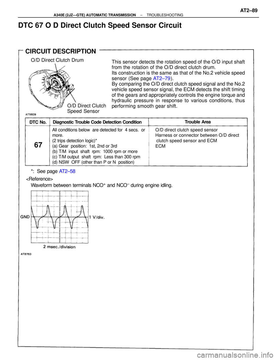
� Waveform between terminals NCO+ and NCO± during engine idling.
This sensor detects the rotation speed of the O/D input shaft
from the rotation of the O/D direct clutch drum.
Its construction is the same as that of the No.2 vehicle speed
sensor (See page AT2±79).
By comparing the O/D direct clutch speed signal and the No.2
vehicle speed sensor signal, the ECM detects the shift timing
of the gears and appropriately controls the engine torque and
hydraulic pressure in response to various conditions, thus
performing smooth gear shift.O/D Direct Clutch Drum
O/D Direct Clutch
Speed Sensor
CIRCUIT DESCRIPTION
DTC 67 O D Direct Clutch Speed Sensor Circuit
± A340E (2JZÐGTE) AUTOMATIC TRANSMISSIONTROUBLESHOOTINGAT2±89
Page 589 of 2543
Pattern Select Switch Circuit
CIRCUIT DESCRIPTION
The ECM memory contains the shift programs for the NORMAL and MANUAL patterns, 2 position, L posi-
tion and the lock±up patterns. Following the programs corresponding to the signals from the pattern select
switch, the park/neutral position switch and other various sensors the ECM switches the solenoid valves
ON and OFF, thereby controlling the transmission gear change and the lock±up clutch operation.
± A340E (2JZÐGTE) AUTOMATIC TRANSMISSIONTROUBLESHOOTINGAT2±105
Page 684 of 2543
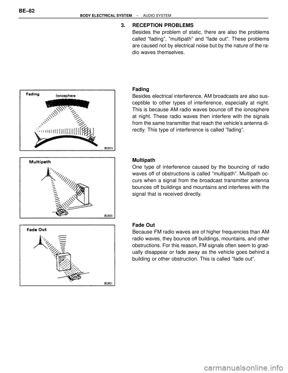
3. RECEPTION PROBLEMS
Besides the problem of static, there are also the problems
called ºfadingº, ºmultipathº and ºfade outº. These problems
are caused not by electrical noise but by the nature of the ra-
dio waves themselves.
Fading
Besides electrical interference, AM broadcasts are also sus-
ceptible to other types of interference, especially at night.
This is because AM radio waves bounce off the ionosphere
at night. These radio waves then interfere with the signals
from the same transmitter that reach the vehicle's antenna di-
rectly. This type of interference is called ºfadingº.
Multipath
One type of interference caused by the bouncing of radio
waves off of obstructions is called ºmultipathº. Multipath oc-
curs when a signal from the broadcast transmitter antenna
bounces off buildings and mountains and interferes with the
signal that is received directly.
Fade Out
Because FM radio waves are of higher frequencies than AM
radio waves, they bounce off buildings, mountains, and other
obstructions. For this reason, FM signals often seem to grad-
ually disappear or fade away as the vehicle goes behind a
building or other obstruction. This is called ºfade outº. BE±82
± BODY ELECTRICAL SYSTEMAUDIO SYSTEM
Page 772 of 2543
IN±35BE±171BE±197BE±179BE±182BE±191BE±189BE±177BE±184BE±165IN±30
See page
Inspection Item
Problem
�ªCRUISEº Indicator light blinks.
�Cruise control system does not set.
�Cruse control system does not
operate.
Diagnosis Trouble Code
Indicator light does not light up
Large speed drop when the cruise control switch
turned to SET.
Vehicle speed fluctuates when cruise control
switch turned to SET.
Set speed deviates on high or low side.
Acceleration response is sluggish when cruise
control switch turned to ªACCELº or ªRESUMEº
Cruise control system does not set.
Cruise control system does not operate.
Set speed does not cancel when brake pedal
depressed.
Set speed does not cancel when parking brake
lever pulled.
Cruise control not cancelled, even when
transmission is shifted to EXCEPT D RANGE.
Set speed does not cancel when clutch pedal
depressed.
Set speed does not cancel when cruise control
switch turned to CANCEL.
Vehicles speed does not decrease when cruise
control switch turned to COAST.
Vehicle speed does not accelerate when cruise
control switch turned to ACCEL.
Vehicle speed does not return to memorized
cruise when control switch turned to RESUME.
Speed can be set below about 40 km/h
(25 mph.)
Cruise control does not disengage even at about
40 km/h (25 mph) or less.
Indicator LightCruise Control ECUActuatorMain Switch
(in Control Switch)Control SwitchStop Light SwitchClutch Switch or Park/
Neutral Position SwitchParking Brake SwitchVehicle Speed SensorSpeed Control Cable
FunctionThrottle Position Sensor
(IDL)Wire Harness
Source voltage drop
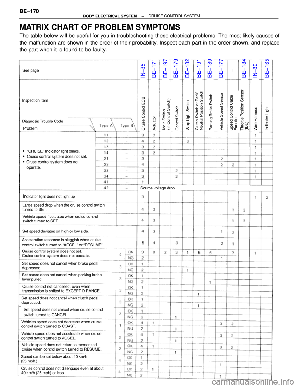
MATRIX CHART OF PROBLEM SYMPTOMS
The table below will be useful for you in troubleshooting these electrical problems. The most likely causes of
the malfunction are shown in the order of their probability. Inspect each part in the order shown, and replace
the part when it is found to be faulty. BE±170
± BODY ELECTRICAL SYSTEMCRUISE CONTROL SYSTEM