Page 1948 of 2543
Disconnect volume air flow meter connector and check voltage between
terminals KS and E1 of engine control module connector.
(1) Disconnect the volume air flow meter connec±
tor.
(2) Turn ignition switch ON.
Measure voltage between terminals KS and E1 of
engine control module connector.
Voltage: 4.5 Ð 5.5 V
(1) Disconnect the volume air flow meter connec±
tor.
(2) Turn ignition switch ON.
Measure voltage between terminals VCC and E1
of engine control module connector.
Voltage: 4.5 Ð 5.5 V
Disconnect volume air flow meter connector and check voltage between
terminals VCC and E1 of engine control module connector.
Check and replace engine control module.
Replace volume air flow meter.
Check and replace engine control module.
EG±440± ENGINE2JZ±GE ENGINE TROUBLESHOOTING
Page 1951 of 2543
INSPECTION PROCEDURE
HINT:
wIf diagnostic trouble code º22º (engine coolant temperature sensor circuit), º24º (intake air temperature
sensor circuit) and º41º (throttle position sensor circuit) are output simultaneously, E2 (sensor ground) may
be open.
(See page EG±219)
Check voltage between VTA1, IDL1 and E2 of engine control module connec-
tor.
(1) Connect SST (check harness ªAº).
(See page EG±404)
SST 09990±01000
(2) Turn ignition switch ON.
(3) Disconnect the vacuum hose from the throttle
body, then apply vacuum to the throttle opener.
(See page EG±219)
Measure voltage between terminals VTA1, IDL1
and E2 of engine control module connector when
the throttle valve is opened gradually from the
closed condition.
Check for intermittent problems.
(See page EG±399)
The voltage should increase steadily in proportion
to the throttle valve opening angle.
Terminal
Throttle Valve
Fully Closed
Fully Open
± ENGINE2JZ±GE ENGINE TROUBLESHOOTINGEG±443
Page 1955 of 2543

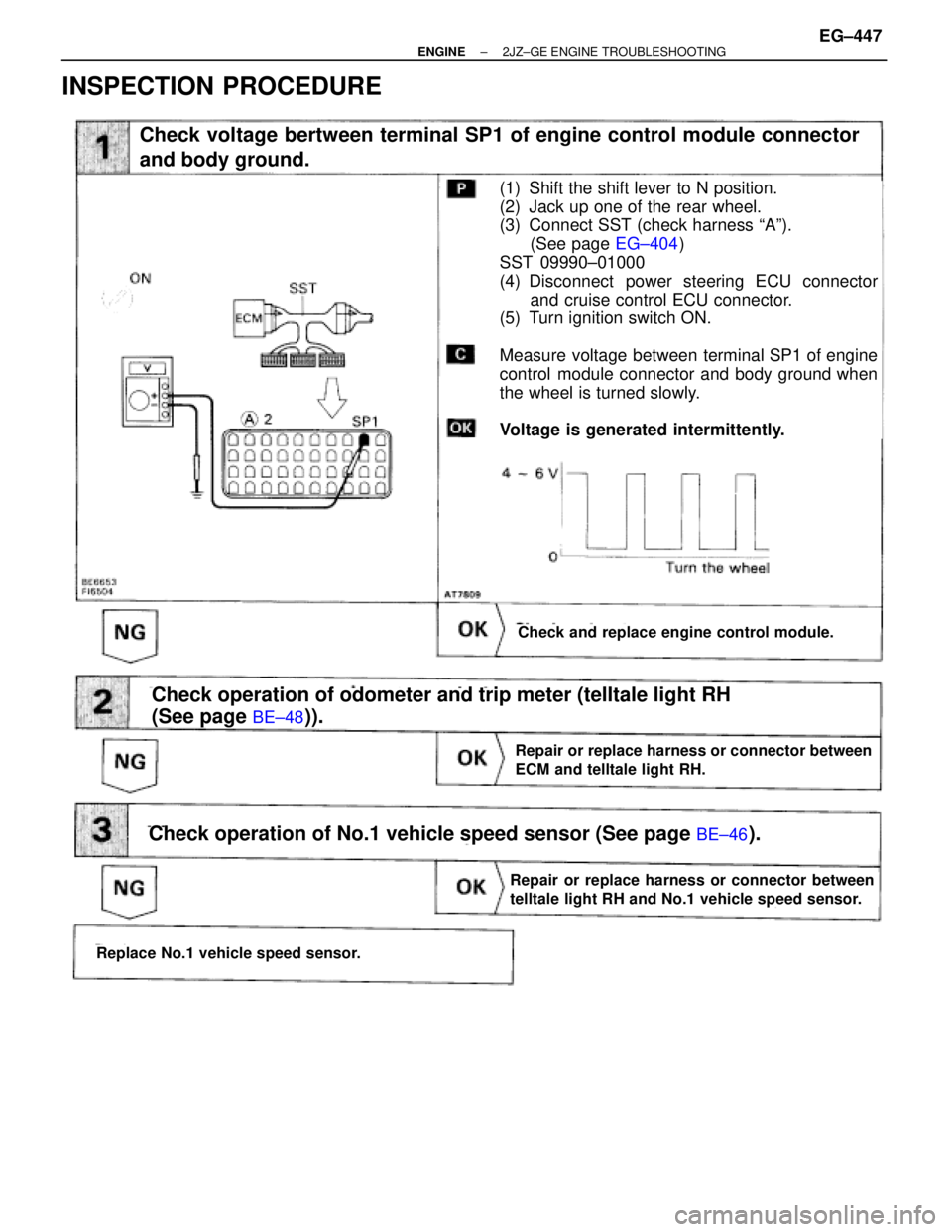
INSPECTION PROCEDURE
(See page
EG±404)
(See page BE±48)).
Check voltage bertween terminal SP1 of engine control module connector
and body ground.
Check and replace engine control module.
(1) Shift the shift lever to N position.
(2) Jack up one of the rear wheel.
(3) Connect SST (check harness ªAº).
(See page EG±404)
SST 09990±01000
(4) Disconnect power steering ECU connector
and cruise control ECU connector.
(5) Turn ignition switch ON.
Measure voltage between terminal SP1 of engine
control module connector and body ground when
the wheel is turned slowly.
Voltage is generated intermittently.
Repair or replace harness or connector between
ECM and telltale light RH.
Check operation of odometer and trip meter (telltale light RH
(See page
BE±48)).
Check operation of No.1 vehicle speed sensor (See page BE±46).
Replace No.1 vehicle speed sensor.
Repair or replace harness or connector between
telltale light RH and No.1 vehicle speed sensor.
± ENGINE2JZ±GE ENGINE TROUBLESHOOTINGEG±447
Page 1956 of 2543

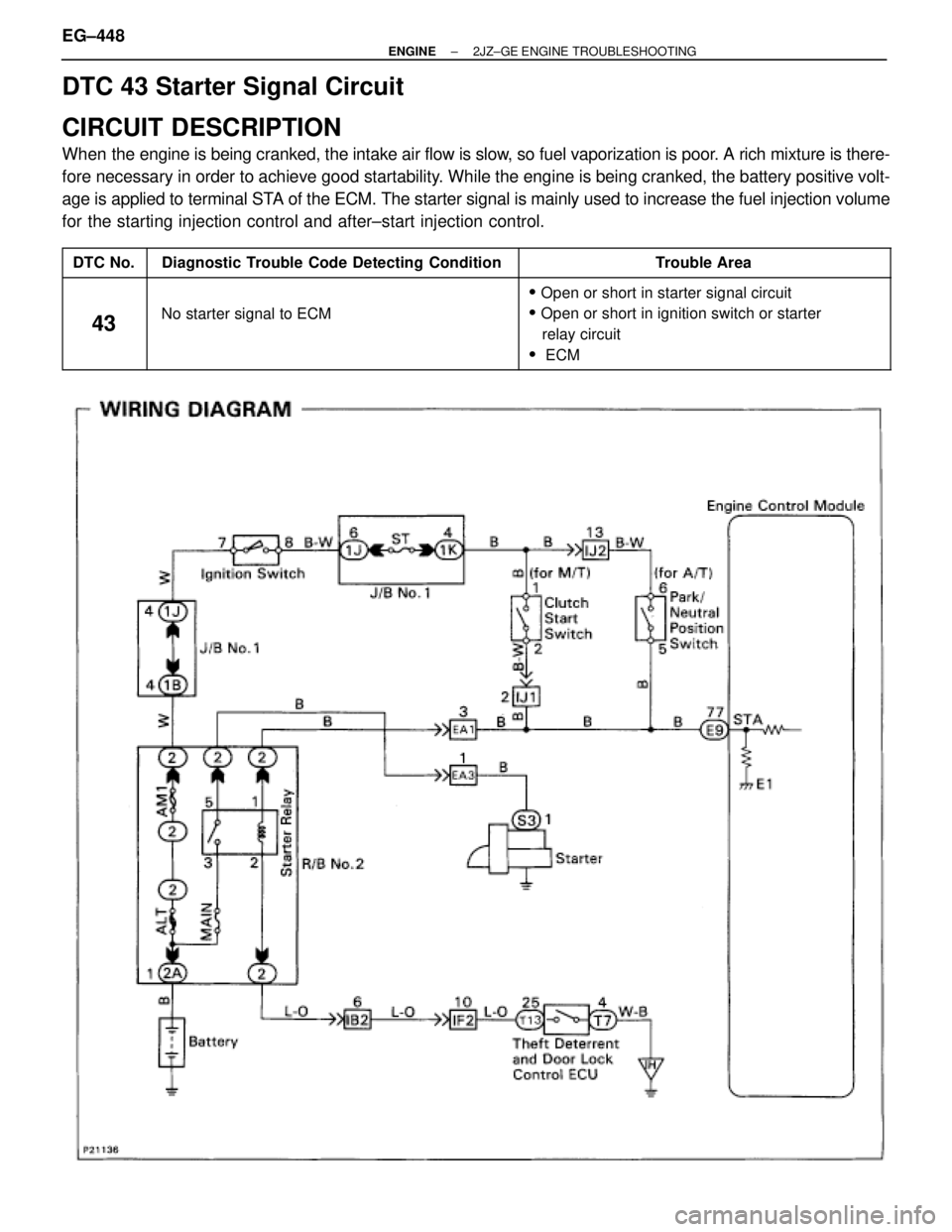
DTC 43 Starter Signal Circuit
CIRCUIT DESCRIPTION
When the engine is being cranked, the intake air flow is slow, so fuel vaporization is poor. A rich mixture is there-
fore necessary in order to achieve good startability. While the engine is being cranked, the battery positive volt-
age is applied to terminal STA of the ECM. The starter signal is mainly used to increase the fuel injection volume
for the starting injection control and after±start injection control.
����� �����DTC No.���������������� ����������������Diagnostic Trouble Code Detecting Condition����������������� �����������������Trouble Area
����� �
���� �����
43
���������������� �
��������������� ���������������� No starter signal to ECM
����������������� �
���������������� ����������������� � Open or short in starter signal circuit
� Open or short in ignition switch or starter
����� �
���� �����
43���������������� �
��������������� ����������������
No starter signal to ECM
����������������� �
���������������� �����������������
Oen or short in ignition switch or starter
relay circuit
� ECM
EG±448± ENGINE2JZ±GE ENGINE TROUBLESHOOTING
Page 1957 of 2543
INSPECTION PROCEDURE
HINT: This diagnostic chart is based on the premise that the engine is being cranked under normal conditions.
If the engine does not crank, proceed to the matrix chart of problem symptoms on page EG±408.
Check output condition of diagnostic trouble code 43.
Check and replace engine control module.
Setting the test mode.
(1) Turn ignition switch OFF.
(2) Connect terminals TE2 and E1 of DLC2.
(3) Turn ignition switch ON.
(Don't start the engine)
(4) Connect terminals TE1 and E1 of DLC2.
Check if code ª43º is output by the malfunction
indicator lamp.
Code ª43º is output.
Start the engine.
Check if code ª43º disappears.
Code ª43º is not output.
Proceed to next circuit inspection shown on ma-
trix chart (See page
EG±408).
Check for open in harness and connector between engine control module
and starter relay (See page
IN±30).
Repair or replace harness or connector.
Check and replace engine control module.
± ENGINE2JZ±GE ENGINE TROUBLESHOOTINGEG±449
Page 1958 of 2543

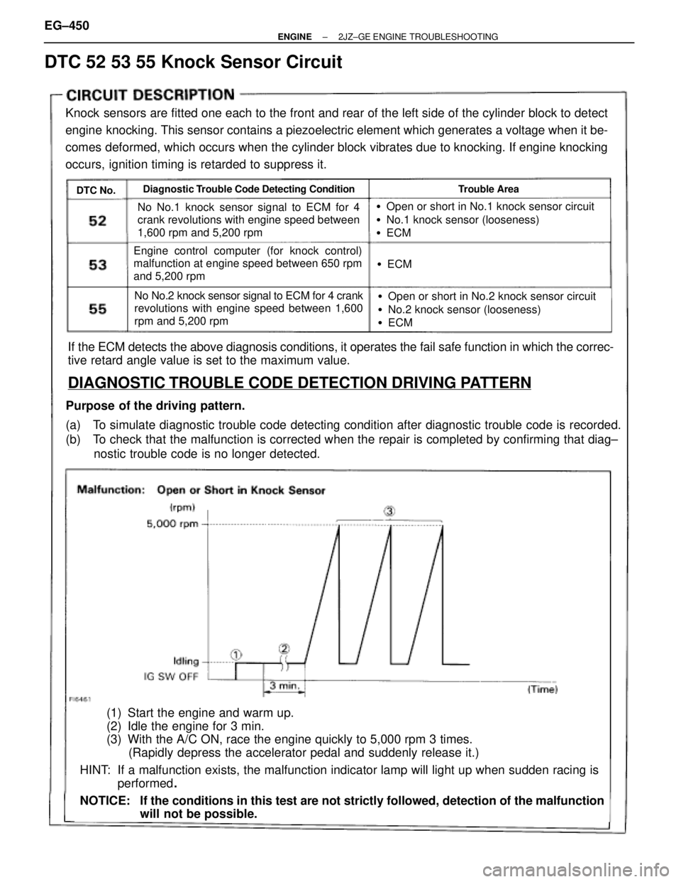
DTC 52 53 55 Knock Sensor Circuit
Knock sensors are fitted one each to the front and rear of the left side of the cylinder block to detect
engine knocking. This sensor contains a piezoelectric element which generates a voltage when it be-
comes deformed, which occurs when the cylinder block vibrates due to knocking. If engine knocking
occurs, ignition timing is retarded to suppress it.
DTC No.Diagnostic Trouble Code Detecting ConditionTrouble Area
No No.1 knock sensor signal to ECM for 4
crank revolutions with engine speed between
1,600 rpm and 5,200 rpm
Engine control computer (for knock control)
malfunction at engine speed between 650 rpm
and 5,200 rpm
No No.2 knock sensor signal to ECM for 4 crank
revolutions with engine speed between 1,600
rpm and 5,200 rpm
�Open or short in No.1 knock sensor circuit
�No.1 knock sensor (looseness)
�ECM
�ECM
�Open or short in No.2 knock sensor circuit
�No.2 knock sensor (looseness)
�ECM
If the ECM detects the above diagnosis conditions, it operates the fail safe function in which the correc-
tive retard angle value is set to the maximum value.
DIAGNOSTIC TROUBLE CODE DETECTION DRIVING PATTERN
Purpose of the driving pattern.
(a) To simulate diagnostic trouble code detecting condition after diagnostic trouble code is recorded.
(b) To check that the malfunction is corrected when the repair is completed by confirming that diag±
nostic trouble code is no longer detected.
(1) Start the engine and warm up.
(2) Idle the engine for 3 min.
(3) With the A/C ON, race the engine quickly to 5,000 rpm 3 times.
(Rapidly depress the accelerator pedal and suddenly release it.)
HINT: If a malfunction exists, the malfunction indicator lamp will light up when sudden racing is
performed.
NOTICE: If the conditions in this test are not strictly followed, detection of the malfunction
will not be possible. EG±450
± ENGINE2JZ±GE ENGINE TROUBLESHOOTING
Page 1966 of 2543
(1) Turn ignition switch ON.
(2) Using SST, connect terminals +B and FP of
data link connector1.
SST 09843±18020
Check that there is pressure in the hose from the
fuel filter.
Fuel pressure can be felt.
Repair or replace harness or connector.Repair or replace harness or connector.
Check fuel pump operation.
Check for open and short in harness and connector between terminals +B
e +B, FP e FP of the data link connector 1 and fuel pump ECU (See page
IN±30).
Check voltage of terminal +B of data link connector 1.
Turn ignition switch ON.
Measure voltage between terminal +B of data link
connector 1 and body ground.
Fuel pressure can be felt.
Check for ECM power source circuit (See page
EG±465), and check for open in harness and con-
nector between terminal +B of data link connec-
tor 1 and main relay.
INSPECTION PROCEDURE
EG±458± ENGINE2JZ±GE ENGINE TROUBLESHOOTING
Page 1967 of 2543

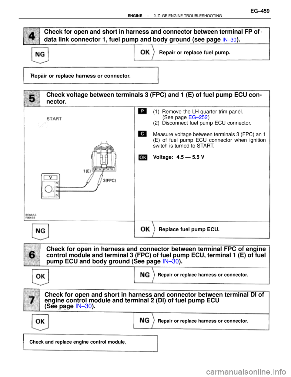
(See page IN±30).
(See page EG±252)
(See page IN±30).
(1) Remove the LH quarter trim panel.
(See page EG±252)
(2) Disconnect fuel pump ECU connector.
Measure voltage between terminals 3 (FPC) an 1
(E) of fuel pump ECU connector when ignition
switch is turned to START.
Voltage: 4.5 Ð 5.5 V
Repair or replace harness or connector.
Check for open and short in harness and connector between terminal FP of
data link connector 1, fuel pump and body ground (see page
IN±30).
Check for open in harness and connector between terminal FPC of engine
control module and terminal 3 (FPC) of fuel pump ECU, terminal 1 (E) of fuel
pump ECU and body ground (See page IN±30).
Repair or replace harness or connector.
Repair or replace fuel pump.
Check voltage between terminals 3 (FPC) and 1 (E) of fuel pump ECU con-
nector.
Replace fuel pump ECU.
Repair or replace harness or connector.
Check for open and short in harness and connector between terminal DI of
engine control module and terminal 2 (DI) of fuel pump ECU
(See page IN±30).
Check and replace engine control module.
± ENGINE2JZ±GE ENGINE TROUBLESHOOTINGEG±459