Page 1971 of 2543
Park Neutral Position Switch Circuit
CIRCUIT DESCRIPTION
The park/neutral position switch goes on when the shift lever is in the N or P shift position. When it goes on the
terminal NSW of the ECM is grounded to body ground via the starter relay and theft deterrent ECU, thus the
terminal NSW voltage becomes 0 V. When the shift lever is in the D, 2, L or R position, the park/neutral position
switch goes off, so the voltage of ECM terminal NSW becomes positive battery voltage, the voltage of the ECM
internal power source.
If the shift lever is moved from the N position to the D position, this signal is used for air±fuel ratio correction
and for idle speed control (estimated control), etc.
When the park/neutral position switch is off, code º51º is output in the test mode diagnosis. (This is not abnor-
mal.)
± ENGINE2JZ±GE ENGINE TROUBLESHOOTINGEG±463
Page 1978 of 2543
Back Up Power Source Circuit
CIRCUIT DESCRIPTION
Battery positive voltage is supplied to terminal BATT of the ECM even when the ignition switch is off for use by
the diagnostic trouble code memory and air±fuel ratio adaptive control value memory, etc.
EG±470± ENGINE2JZ±GE ENGINE TROUBLESHOOTING
Page 1980 of 2543
Injector Circuit
CIRCUIT DESCRIPTION
The injectors are located in the intake manifold. They inject fuel into the cylinders based on the signals
from the engine control module.
INSPECTION USING OSCILLOSCOPE
�With the engine idling measure waveform between terminals #10 ~ 60 and E01 of engine
control module.
HINT: The correct waveform is as shown.
EG±472± ENGINE2JZ±GE ENGINE TROUBLESHOOTING
Page 1982 of 2543
(See page
EG±202)
Check for open in harness and connector between terminal E)1, EO2 of ECM
connector and body ground (See page
IN±30).
Disconnect injector connector. (See page EG±202)
Measure resistance of injector.
Resistance: 13.4 Ð 14.2 � at 20°C (68°F)
Check injector volume of injector.
(See page EG±207)
�Injection volume
70 Ð 88 cc/15 sec.
(4.3 Ð 5.4 cu in./15 sec.)
Difference between each injector:
Less than 9 cc (0.5 cu in.)
�Leakage
Fuel drop: One drip or less per minute
Replace injector.
Check and replace engine control module.
Check injectors.
Repair or replace harness or connector.
Replace injector.
Check and replace engine control module.
EG±474± ENGINE2JZ±GE ENGINE TROUBLESHOOTING
Page 1989 of 2543
VSV Circuit for Fuel Pressure Control (Only for California spec.)
CIRCUIT DESCRIPTION
The ECM turns on a VSV (Vacuum Switching
Valve) to draw air into the diaphragm cham-
ber of the pressure regulator if it detects that
the temperature of the engine coolant is too
high during engine starting.
The air drawn into the chamber increases the
fuel pressure to prevent fuel vapor lock at
high engine temperature in order to help the
engine start when it is warm.
`Fuel pressure control ends approx. 120 sec.
after then engine is started.
± ENGINE2JZ±GE ENGINE TROUBLESHOOTINGEG±481
Page 1990 of 2543
INSPECTION PROCEDURE
Check VSV for fuel pressure control.
(1) Remove VSV.
(2) Disconnect VSV connector.
(1) Measure resistance between terminals.
(2) Measure resistance between each terminal
and the body.
(1) Resistance: 33 Ð 39 � at 20°C (68°F)
(2) Resistance: 1 M� or higher
Check operation of VSV when battery positive
voltage is applied and released to the VSV termi-
nals.
Battery positive voltage is applied:
Air from port E is flowing out through the air fil-
ter.
Battery positive voltage is not applied:
Air from port E is flowing out through port G.
Replace VSV for fuel pressure control. EG±482
± ENGINE2JZ±GE ENGINE TROUBLESHOOTING
Page 2003 of 2543

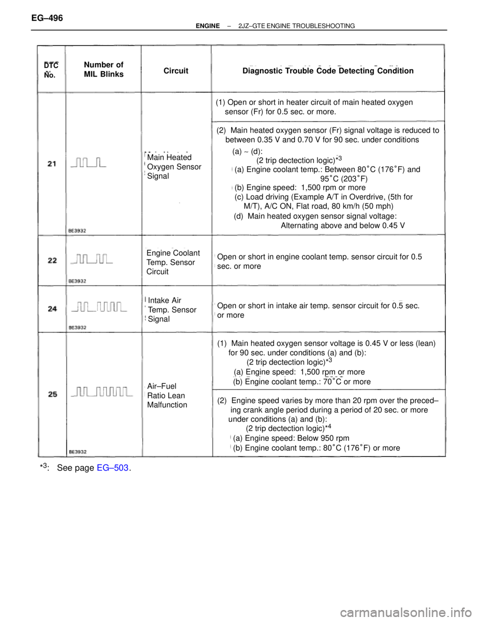
DTC
No.
Number of
MIL BlinksCircuitDiagnostic Trouble Code Detecting Condition
(1) Open or short in heater circuit of main heated oxygen
sensor (Fr) for 0.5 sec. or more.
(2) Main heated oxygen sensor (Fr) signal voltage is reduced to
between 0.35 V and 0.70 V for 90 sec. under conditions
Main Heated
Oxygen Sensor
Signal(a) ~ (d):
(2 trip dectection logic)*3
(a) Engine coolant temp.: Between 80°C (176°F) and
95°C (203°F)
(b) Engine speed: 1,500 rpm or more
(c) Load driving (Example A/T in Overdrive, (5th for
M/T), A/C ON, Flat road, 80 km/h (50 mph)
(d) Main heated oxygen sensor signal voltage:
Alternating above and below 0.45 V
Open or short in engine coolant temp. sensor circuit for 0.5
sec. or more
Open or short in intake air temp. sensor circuit for 0.5 sec.
or more
(1) Main heated oxygen sensor voltage is 0.45 V or less (lean)
for 90 sec. under conditions (a) and (b):
(2 trip dectection logic)*3
(a) Engine speed: 1,500 rpm or more
(b) Engine coolant temp.: 70°C or more
(a) Engine speed: Below 950 rpm
(b) Engine coolant temp.: 80°C (176°F) or more
(2 trip dectection logic)*4
(2) Engine speed varies by more than 20 rpm over the preced±
ing crank angle period during a period of 20 sec. or more
under conditions (a) and (b):
Intake Air
Temp. Sensor
Signal
Engine Coolant
Temp. Sensor
Circuit
Air±Fuel
Ratio Lean
Malfunction
*3: See page EG±503. EG±496
± ENGINE2JZ±GTE ENGINE TROUBLESHOOTING
Page 2004 of 2543

�������������������� �
������������������� �
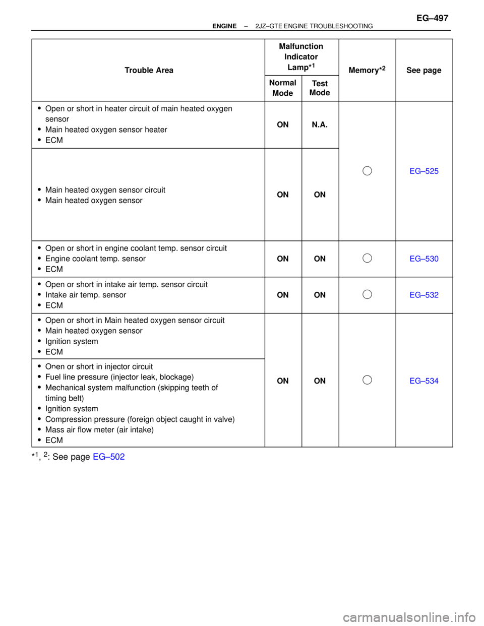
������������������� ��������������������Trouble Area
������� �
������ �
������ �������
Malfunction
Indicator
Lamp*
1
������ �
����� �
����� ������Memory*2
������ �
����� �
����� ������See page
�������������������� �
������������������� ��������������������
Trouble Area
���� �
��� ����
Normal
Mode���� �
��� ����
Test
Mode������ �
����� ������
Memory
������ �
����� ������
See page
�������������������� �
������������������� �
������������������� �
������������������� ��������������������
�Open or short in heater circuit of main heated oxygen
sensor
�Main heated oxygen sensor heater
�ECM
���� �
��� �
��� �
��� ����
ON
���� �
��� �
��� �
��� ����
N.A.
������ �
����� �
����� �
����� ������
������ �
����� �
����� �
����� ������
�������������������� �
������������������� �
������������������� �
������������������� ���������������������Main heated oxygen sensor circuit
Mi h td
���� �
��� �
��� �
��� ����ON
���� �
��� �
��� �
��� ����ON
������ �
����� �
����� �
����� ������
�
������ �
����� �
����� �
����� ������
EG±525
���������������������Main heated oxygen sensor����
ON
����
ON
�������������������������������� ��������������������Main heated oxygen sensor���� �������� ���������� ������������ ������
������������������������������������������������������������ ������������������������ �������� ���������� ������������ ������
������������������������������������������������������������ ������������������������ �������� ���������� ������������ ������
������������������������������������������������������������ �
������������������� �
������������������� ��������������������
�Open or short in engine coolant temp. sensor circuit
�Engine coolant temp. sensor
�ECM
���� �
��� �
��� ����ON
���� �
��� �
��� ����ON
������ �
����� �
����� �������
������ �
����� �
����� ������EG±530
�������������������� �
������������������� �
������������������� ��������������������
�Open or short in intake air temp. sensor circuit
�Intake air temp. sensor
�ECM
���� �
��� �
��� ����ON
���� �
��� �
��� ����ON
������ �
����� �
����� �������
������ �
����� �
����� ������EG±532
�������������������� ���������������������Open or short in Main heated oxygen sensor circuit���� �������� ���������� ������������ ������
�������������������� ��������������������Oen or short in Main heated oxygen sensor circuit
�Main heated oxygen sensor���� �������� ���������� ������������ ������
�������������������� ��������������������Main heated oxygen sensor
�Ignition system���� �������� ���������� ������������ ������
�������������������� ��������������������
gy
�ECM���� �������� ���������� ������������ ������
�������������������� ���������������������Open or short in injector circuit���� �������� ���������� ������������ ������
�������������������� ���������������������Oen or short in injector circuit
�Fuel linepressure (injector leak blockage)���� ����ON���� ����ON������ ������������� ������EG 534��������������������
�Fuel line pressure (injector leak, blockage)
�Mechanical system malfunction (skipping teeth of����ON����ON�������������EG±534�������������������� ���������������������Mechanical system malfunction (skipping teeth of
timing belt)���� �������� ���������� ������������ ������
�������������������� ��������������������timing belt)
�Ignition system
���� �������� ���������� ������������ ������
�������������������� ���������������������Ignition system
�Compression pressure (foreign object caught in valve)
���� �������� ���������� ������������ ������
�������������������� ���������������������Compression pressure (foreign object caught in valve)
M i fl t (i itk)���� �������� ���������� ������������ ������
�������������������� ���������������������Mass air flow meter (air intake)
ECM���� �������� ���������� ������������ ������
���������������������ECM��������������������
*1, 2: See page EG±502
± ENGINE2JZ±GTE ENGINE TROUBLESHOOTINGEG±497