Page 1139 of 2248
 Burned or shorted contacts
2) Broken or weak spring
3) Damaged harness
4) Worn or corroded mating surface of")
B: INSPECTION
1. HORN SWITCH
Ensure that horn switch is free from the following defects:
1) Burned or shorted contacts
2) Broken or weak spring
3) Damaged harness
4) Worn or corroded mating surface of horn plate
B6M0126A
2. HORN RELAY
Check continuity between terminals as indicated in table
below, when connecting the battery to terminals No. 1 and
No. 2.
When current flows. Between terminals
No. 2 and No. 3Continuity exists.
When current does not flow. Between terminals
No. 2 and No. 3Continuity does not
exist.
Between terminals
No. 1 and No. 2Continuity exists.
B6M0127
3. HORN
Make sure that horn sounds when battery voltage is
applied between connector terminal and horn body.
4. CIGARETTE LIGHTER
1) Remove plug. Then, check element’s contact for wear,
and element for accumulation of ashes, foreign particles,
etc.
2) Check element for discontinuity.
3) Remove socket and clean element. Then, check for
wear or foreign particles on element’s contact and mating
surface.
4) Ensure that cigarette lighter returns within 20 seconds
after it is turned to ON.
16. Power Window
A: REMOVAL AND INSTALLATION
1. MAIN SWITCH, SUB SWITCH AND POWER
WINDOW MOTOR
Refer to 5-2 [W2A2] as for removal and installation of
power window main switch, sub switch and motor.
NOTE:
To remove the power window motor, it is necessary to dis-
assemble the door component parts.
38
6-2SERVICE PROCEDURE
16. Power Window
Page 1140 of 2248
 Burned or shorted contacts
2) Broken or weak spring
3) Damaged harness
4) Worn or corroded mating surface of")
B: INSPECTION
1. HORN SWITCH
Ensure that horn switch is free from the following defects:
1) Burned or shorted contacts
2) Broken or weak spring
3) Damaged harness
4) Worn or corroded mating surface of horn plate
B6M0126A
2. HORN RELAY
Check continuity between terminals as indicated in table
below, when connecting the battery to terminals No. 1 and
No. 2.
When current flows. Between terminals
No. 2 and No. 3Continuity exists.
When current does not flow. Between terminals
No. 2 and No. 3Continuity does not
exist.
Between terminals
No. 1 and No. 2Continuity exists.
B6M0127
3. HORN
Make sure that horn sounds when battery voltage is
applied between connector terminal and horn body.
4. CIGARETTE LIGHTER
1) Remove plug. Then, check element’s contact for wear,
and element for accumulation of ashes, foreign particles,
etc.
2) Check element for discontinuity.
3) Remove socket and clean element. Then, check for
wear or foreign particles on element’s contact and mating
surface.
4) Ensure that cigarette lighter returns within 20 seconds
after it is turned to ON.
16. Power Window
A: REMOVAL AND INSTALLATION
1. MAIN SWITCH, SUB SWITCH AND POWER
WINDOW MOTOR
Refer to 5-2 [W2A2] as for removal and installation of
power window main switch, sub switch and motor.
NOTE:
To remove the power window motor, it is necessary to dis-
assemble the door component parts.
38
6-2SERVICE PROCEDURE
16. Power Window
Page 1142 of 2248
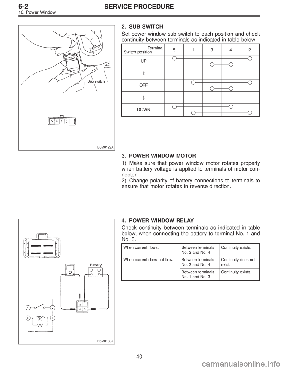
B6M0129A
2. SUB SWITCH
Set power window sub switch to each position and check
continuity between terminals as indicated in table below:
Terminal
Switch position51342
UP��
��
*
OFF��
��
*
DOWN��
��
3. POWER WINDOW MOTOR
1) Make sure that power window motor rotates properly
when battery voltage is applied to terminals of motor con-
nector.
2) Change polarity of battery connections to terminals to
ensure that motor rotates in reverse direction.
B6M0130A
4. POWER WINDOW RELAY
Check continuity between terminals as indicated in table
below, when connecting the battery to terminal No. 1 and
No. 3.
When current flows. Between terminals
No. 2 and No. 4Continuity exists.
When current does not flow. Between terminals
No. 2 and No. 4Continuity does not
exist.
Between terminals
No. 1 and No. 3Continuity exists.
40
6-2SERVICE PROCEDURE
16. Power Window
Page 1148 of 2248
B6M0144A
3. SUNROOF RELAY
Check continuity between terminals as indicated in table
below, when battery voltage is applied between terminals
No. 1 and No. 3.
When current flows. Between terminals
No. 2 and No. 4Continuity exists.
When current does not flow. Between terminals
No. 2 and No. 4Continuity does not
exist.
Between terminals
No. 1 and No. 3Continuity exists.
B6M0354
20. Radio, Speaker and Antenna
A: REMOVAL AND INSTALLATION
1. RADIO BODY
1) Remove hand brake cover.
2) Remove console cover.
3) Remove screws which secure center panel. Remove
center panel.
B6M0355
4) Remove fitting screws, and slightly pull radio out of
instrument panel.
5) Disconnect connectors and antenna feeder cord.
B6M0146
2. FRONT SPEAKER
1) Remove gusset speaker from behind the rearview mir-
ror while disconnecting connector.
2) Remove door trim panel.
45
6-2SERVICE PROCEDURE
19. Sunroof - 20. Radio, Speaker and Antenna
Page 1149 of 2248
B6M0144A
3. SUNROOF RELAY
Check continuity between terminals as indicated in table
below, when battery voltage is applied between terminals
No. 1 and No. 3.
When current flows. Between terminals
No. 2 and No. 4Continuity exists.
When current does not flow. Between terminals
No. 2 and No. 4Continuity does not
exist.
Between terminals
No. 1 and No. 3Continuity exists.
B6M0354
20. Radio, Speaker and Antenna
A: REMOVAL AND INSTALLATION
1. RADIO BODY
1) Remove hand brake cover.
2) Remove console cover.
3) Remove screws which secure center panel. Remove
center panel.
B6M0355
4) Remove fitting screws, and slightly pull radio out of
instrument panel.
5) Disconnect connectors and antenna feeder cord.
B6M0146
2. FRONT SPEAKER
1) Remove gusset speaker from behind the rearview mir-
ror while disconnecting connector.
2) Remove door trim panel.
45
6-2SERVICE PROCEDURE
19. Sunroof - 20. Radio, Speaker and Antenna
Page 1155 of 2248

B6M0361A
22. Security System
A: REMOVAL AND INSTALLATION
1. STARTER INTERRUPT RELAY
NOTE:
The starter interrupt relay and headlight alarm relay use the
same parts and are mounted parallel to each other.
Therefore, before removal and installation, identify the
starter interrupt relay by the color of its wiring connection.
1) Remove instrument panel lower cover.
2) Disconnect connector of starter interrupt relay.
3) Remove starter interrupt relay.
4) Installation is in the reverse order of removal.
B6M0361A
2. HEADLIGHT ALARM RELAY
NOTE:
The headlight alarm relay and starter interrupt relay use the
same parts and are mounted parallel to each other.
Therefore, before removal and installation, identify the
headlight alarm relay by the color of its wiring connection.
1) Remove instrument panel lower cover.
2) Disconnect connector of headlight alarm relay.
3) Remove headlight alarm relay.
4) Installation is in the reverse order of removal.
B6M0363A
3. ENGINE HOOD SWITCH
1) Disconnect connector of engine hood switch from bot-
tom side of switch body.
2) Remove headlight (LH).
3) Remove attaching bolt, and then remove engine hood
switch.
4) Installation is in the reverse order of removal.
51
6-2SERVICE PROCEDURE
22. Security System
Page 1159 of 2248
 Disconnect connector of starter interrupt relay.
2) Connect battery to terminal No.1 and ground terminal
No. 2.
3) Check continuity between termina")
B6M0375A
B: INSPECTION
1. STARTER INTERRUPT RELAY
1) Disconnect connector of starter interrupt relay.
2) Connect battery to terminal No.1 and ground terminal
No. 2.
3) Check continuity between terminals as indicated in
table below:
When current flows. Between terminals
No. 3 and No. 5Continuity does not
exist.
When current does not flow. Between terminals
No. 3 and No. 5Continuity exists.
Between terminals
No. 1 and No. 2Continuity exists.
G6M0134
2. HEADLIGHT ALARM RELAY
1) Disconnect connector of headlight alarm relay.
2) Connect battery to terminal No. 1 and ground terminal
No. 2.
3) Check continuity between terminals as indicated in
table below:
When current flows. Between terminals
No. 3 and No. 5Continuity does not
exist.
Between terminals
No. 3 and No. 4Continuity exists.
When current does not flow. Between terminals
No. 3 and No. 5Continuity exists.
Between terminals
No. 3 and No. 4Continuity does not
exist.
Between terminals
No. 1 and No. 2Continuity exists.
B6M0376
3. ENGINE HOOD SWITCH
1) Disconnect connector of engine hood switch.
2) Check continuity between terminals when push rod is
pushed in 1.5 mm (0.059 in) of its stroke.
Terminal
Switch position12
When push rod is
pushed in.
When push rod is
released.��
55
6-2SERVICE PROCEDURE
22. Security System
Page 1165 of 2248
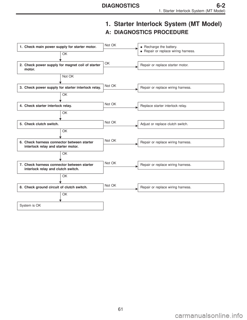
1. Starter Interlock System (MT Model)
A: DIAGNOSTICS PROCEDURE
1. Check main power supply for starter motor.
OK
�Not OK
�Recharge the battery.
�Repair or replace wiring harness.
2. Check power supply for magnet coil of starter
motor.
Not OK
�OK
Repair or replace starter motor.
3. Check power supply for starter interlock relay.
OK
�Not OK
Repair or replace wiring harness.
4. Check starter interlock relay.
OK
�Not OK
Replace starter interlock relay.
5. Check clutch switch.
OK
�Not OK
Adjust or replace clutch switch.
6. Check harness connector between starter
interlock relay and starter motor.
OK
�Not OK
Repair or replace wiring harness.
7. Check harness connector between starter
interlock relay and clutch switch.
OK
�Not OK
Repair or replace wiring harness.
8. Check ground circuit of clutch switch.
OK
�Not OK
Repair or replace wiring harness.
System is OK
�
�
�
�
�
�
�
�
61
6-2DIAGNOSTICS
1. Starter Interlock System (MT Model)