Page 804 of 2248
20. Hydraulic Unit for ABS/TCS System
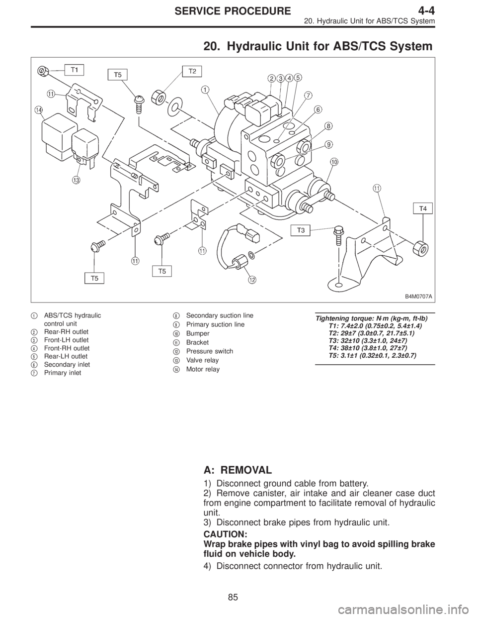
B4M0707A
�1ABS/TCS hydraulic
control unit
�
2Rear-RH outlet
�
3Front-LH outlet
�
4Front-RH outlet
�
5Rear-LH outlet
�
6Secondary inlet
�
7Primary inlet�
8Secondary suction line
�
9Primary suction line
�
10Bumper
�
11Bracket
�
12Pressure switch
�
13Valve relay
�
14Motor relay
Tightening torque: N⋅m (kg-m, ft-lb)
T1: 7.4±2.0 (0.75±0.2, 5.4±1.4)
T2: 29±7 (3.0±0.7, 21.7±5.1)
T3: 32±10 (3.3±1.0, 24±7)
T4: 38±10 (3.8±1.0, 27±7)
T5: 3.1±1 (0.32±0.1, 2.3±0.7)
A: REMOVAL
1) Disconnect ground cable from battery.
2) Remove canister, air intake and air cleaner case duct
from engine compartment to facilitate removal of hydraulic
unit.
3) Disconnect brake pipes from hydraulic unit.
CAUTION:
Wrap brake pipes with vinyl bag to avoid spilling brake
fluid on vehicle body.
4) Disconnect connector from hydraulic unit.
85
4-4SERVICE PROCEDURE
20. Hydraulic Unit for ABS/TCS System
Page 805 of 2248
 Remove bolts which secure hydraulic unit bracket, and
remove hydraulic unit from engine compartment.
CAUTION:
�Hydraulic unit cannot be disassembled. Do not
attempt to loosen bolts and nuts")
B4M0628
5) Remove bolts which secure hydraulic unit bracket, and
remove hydraulic unit from engine compartment.
CAUTION:
�Hydraulic unit cannot be disassembled. Do not
attempt to loosen bolts and nuts.
�Do not drop or bump hydraulic unit.
�Do not turn the hydraulic unit upside down or place
it on its side.
�Be careful to prevent foreign particles from getting
into hydraulic unit.
�Do not pull harness disconnecting harness connec-
tor.
B: INSPECTION
1) Check connected and fixed condition of connector.
2) Check for discontinuity or short circuits.
Condition Terminal number Standard Diagram Terminal location
Valve relayTurning off
electricity.A—B90Ω
B4M0629A
B4M0630
C—F0Ω
C—E
Turning on
electricity between
A and B.
(DC 12 V)C—F
C—E0Ω
Motor relayTurning off
electricity.a—b* 57Ω
B4M0631AB4M0632
c—d
Turning on
electricity between
a and b.
(DC 12 V)c—d0Ω
*: Attach circuit tester positive probe to terminal“a”and its negative probe to terminal“b”and measure the circuit resistance.
86
4-4SERVICE PROCEDURE
20. Hydraulic Unit for ABS/TCS System
Page 818 of 2248
B4M0628
G: INSTALLATION
1) Install hydraulic unit and bracket.
Tightening torque:
32±7 N⋅m (3.3±0.7 kg-m, 23.9±5.1 ft-lb)
2) Connect brake pipes to their correct hydraulic unit con-
nections.
3) Connect connector to hydraulic unit.
4) Install canister.
5) Install air cleaner case.
6) Install air intake duct.
7) Connect ground cable to battery.
CAUTION:
Cover relay securely with rubber boot.
21. ABS/TCS Control Module
A: REMOVAL
1) Disconnect ground cable from battery.
2) Remove floor mat located under lower right side of front
seat.
B4M0643A
3) Remove screw which secure ABS/TCS control module
from the body.
4) Disconnect connector from ABS/TCS control module.
B: INSPECTION
Check that connector is connected correctly and that con-
nector terminal sliding resistance is correct.
99
4-4SERVICE PROCEDURE
20. Hydraulic Unit for ABS/TCS System - 21. ABS/TCS Control Module
Page 819 of 2248
B4M0628
G: INSTALLATION
1) Install hydraulic unit and bracket.
Tightening torque:
32±7 N⋅m (3.3±0.7 kg-m, 23.9±5.1 ft-lb)
2) Connect brake pipes to their correct hydraulic unit con-
nections.
3) Connect connector to hydraulic unit.
4) Install canister.
5) Install air cleaner case.
6) Install air intake duct.
7) Connect ground cable to battery.
CAUTION:
Cover relay securely with rubber boot.
21. ABS/TCS Control Module
A: REMOVAL
1) Disconnect ground cable from battery.
2) Remove floor mat located under lower right side of front
seat.
B4M0643A
3) Remove screw which secure ABS/TCS control module
from the body.
4) Disconnect connector from ABS/TCS control module.
B: INSPECTION
Check that connector is connected correctly and that con-
nector terminal sliding resistance is correct.
99
4-4SERVICE PROCEDURE
20. Hydraulic Unit for ABS/TCS System - 21. ABS/TCS Control Module
Page 863 of 2248
1. Air Conditioning System
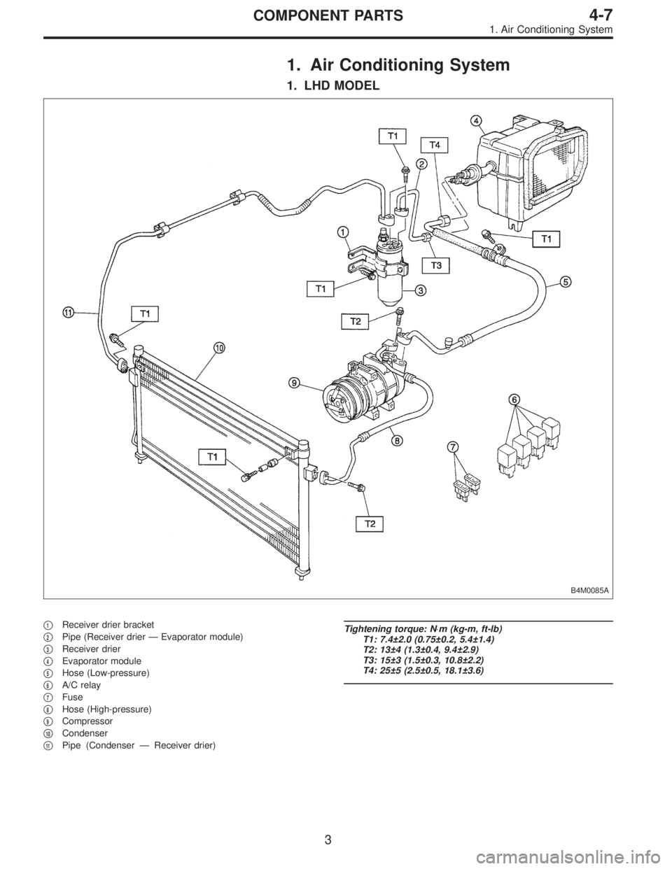
1. LHD MODEL
B4M0085A
�1Receiver drier bracket
�
2Pipe (Receiver drier—Evaporator module)
�
3Receiver drier
�
4Evaporator module
�
5Hose (Low-pressure)
�
6A/C relay
�
7Fuse
�
8Hose (High-pressure)
�
9Compressor
�
10Condenser
�
11Pipe (Condenser—Receiver drier)
Tightening torque: N⋅m (kg-m, ft-lb)
T1: 7.4±2.0 (0.75±0.2, 5.4±1.4)
T2: 13±4 (1.3±0.4, 9.4±2.9)
T3: 15±3 (1.5±0.3, 10.8±2.2)
T4: 25±5 (2.5±0.5, 18.1±3.6)
3
4-7COMPONENT PARTS
1. Air Conditioning System
Page 864 of 2248
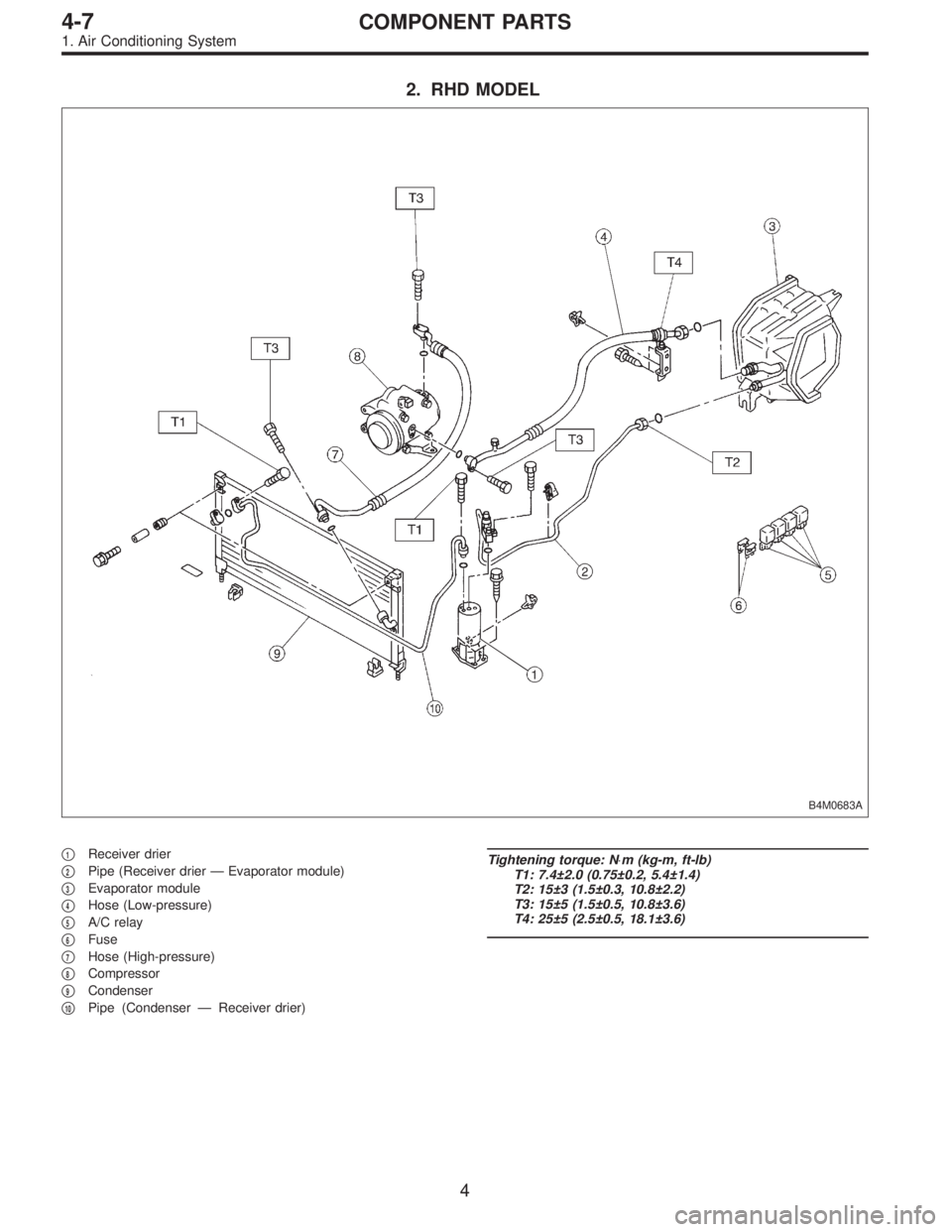
2. RHD MODEL
B4M0683A
�1Receiver drier
�
2Pipe (Receiver drier—Evaporator module)
�
3Evaporator module
�
4Hose (Low-pressure)
�
5A/C relay
�
6Fuse
�
7Hose (High-pressure)
�
8Compressor
�
9Condenser
�
10Pipe (Condenser—Receiver drier)
Tightening torque: N⋅m (kg-m, ft-lb)
T1: 7.4±2.0 (0.75±0.2, 5.4±1.4)
T2: 15±3 (1.5±0.3, 10.8±2.2)
T3: 15±5 (1.5±0.5, 10.8±3.6)
T4: 25±5 (2.5±0.5, 18.1±3.6)
4
4-7COMPONENT PARTS
1. Air Conditioning System
Page 903 of 2248
G4M0649
17. Relay and Fuse
A: LOCATION
Relays used with A/C system are located as shown in fig-
ure.
1) A/C relay
2) Main fan (radiator fan) relay
3) Sub fan (condenser fan) relay
4) Sub fan (condenser fan) water temperature relay
5) Fuses (10 A and 20 A)
G4M0651
B: INSPECTION
1) Check conduction with a circuit tester (ohm range)
according to the following table in figure.
B4M0105A
2) Replace relays which do not meet specifications.
41
4-7SERVICE PROCEDURE
17. Relay and Fuse
Page 971 of 2248
![SUBARU LEGACY 1995 Service Repair Manual B5M0304
15. Roof Rack (Wagon only, if
equipped)
A: REMOVAL
1) Remove roof trim, rear quarter trim, pillar trim, etc.
<Ref. to 5-3 [W5A0].>
2) Remove flange bolts.
3) Remove flange nuts.
4) Remove roof](/manual-img/17/57432/w960_57432-970.png "SUBARU LEGACY 1995 Service Repair Manual B5M0304
15. Roof Rack (Wagon only, if
equipped)
A: REMOVAL
1) Remove roof trim, rear quarter trim, pillar trim, etc.
<Ref. to 5-3 [W5A0].>
2) Remove flange bolts.
3) Remove flange nuts.
4) Remove roof")
B5M0304
15. Roof Rack (Wagon only, if
equipped)
A: REMOVAL
1) Remove roof trim, rear quarter trim, pillar trim, etc.
2) Remove flange bolts.
3) Remove flange nuts.
4) Remove roof rail.
B: INSTALLATION
Installation is in the reverse order of removal.
CAUTION:
To prevent deformation, be sure to install roof rail in
steps 4), 3), 2) and 1), in that order.
B5M0307A
16. Sunroof
A: REMOVAL
1. GLASS LID ASSEMBLY
1) Completely open sun shade. (Push it back far.)
2) Remove a clip and detach guide rail cover.
3) Remove six nuts from the left and right lid bracket.
4) Working inside, slightly raise glass lid assembly until it
is disengaged from lid bracket.
5) Hold both ends of glass lid assembly and remove it at
an angle.
B5M0308B
2. SUNROOF MOTOR AND RELAY
1) Remove center pillar trim upper.
2) Remove front pillar trim upper.
3) Remove assist grip on left side.
4) Remove sunvisor with hook.
5) Remove sunroof switch.
6) Remove rearview mirror.
7) While rolling up roof trim, disconnect harness clips and
connector.
8) While rolling up roof trim, remove spot lamp bracket and
sunroof motor.
51
5-1SERVICE PROCEDURE
15. Roof Rack (Wagon only, if equipped) - 16. Sunroof
 Install hydraulic unit and bracket.
Tightening torque:
32±7 N⋅m (3.3±0.7 kg-m, 23.9±5.1 ft-lb)
2) Connect brake pipes to their correct hydraulic unit con-
nections. <Re")
 Install hydraulic unit and bracket.
Tightening torque:
32±7 N⋅m (3.3±0.7 kg-m, 23.9±5.1 ft-lb)
2) Connect brake pipes to their correct hydraulic unit con-
nections. <Re")
 A/C relay
2) Main fan (radiator fan) relay
3) Sub fan (condenser fan) relay
4) Sub fan (condense")