Page 1221 of 2248
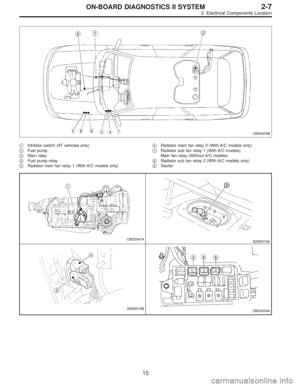
OBD0003B
�1Inhibitor switch (AT vehicles only)
�
2Fuel pump
�
3Main relay
�
4Fuel pump relay
�
5Radiator main fan relay 1 (With A/C models only)�
6Radiator main fan relay 2 (With A/C models only)
�
7Radiator sub fan relay 1 (With A/C models)
Main fan relay (Without A/C models)
�
8Radiator sub fan relay 2 (With A/C models only)
�
9Starter
OBD0047AB2M0216A
B2M0218BOBD0034A
15
2-7ON-BOARD DIAGNOSTICS II SYSTEM
2. Electrical Components Location
Page 1225 of 2248
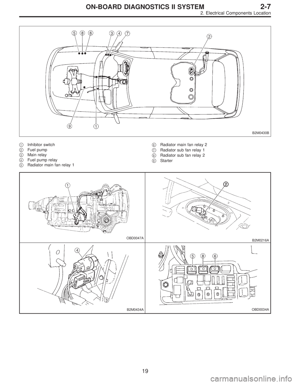
B2M0430B
�1Inhibitor switch
�
2Fuel pump
�
3Main relay
�
4Fuel pump relay
�
5Radiator main fan relay 1�
6Radiator main fan relay 2
�
7Radiator sub fan relay 1
�
8Radiator sub fan relay 2
�
9Starter
OBD0047AB2M0216A
B2M0434AOBD0034A
19
2-7ON-BOARD DIAGNOSTICS II SYSTEM
2. Electrical Components Location
Page 1231 of 2248
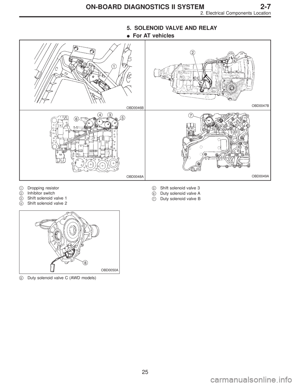
5. SOLENOID VALVE AND RELAY
�For AT vehicles
OBD0046BOBD0047B
OBD0048AOBD0049A
�1Dropping resistor
�
2Inhibitor switch
�
3Shift solenoid valve 1
�
4Shift solenoid valve 2�
5Shift solenoid valve 3
�
6Duty solenoid valve A
�
7Duty solenoid valve B
OBD0050A
�8Duty solenoid valve C (AWD models)
25
2-7ON-BOARD DIAGNOSTICS II SYSTEM
2. Electrical Components Location
Page 1243 of 2248
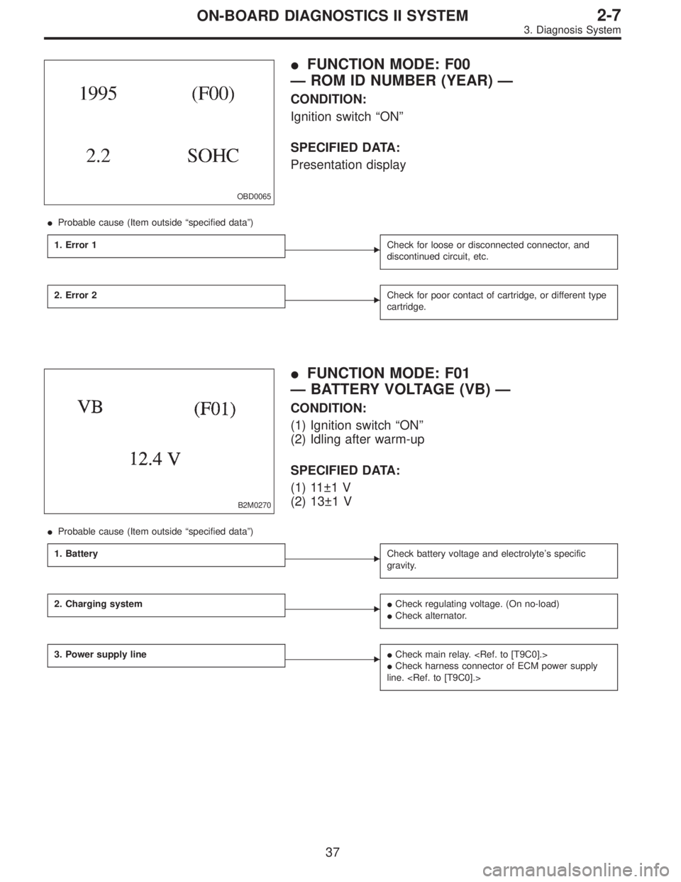
OBD0065
�FUNCTION MODE: F00
— ROM ID NUMBER (YEAR) —
CONDITION:
Ignition switch“ON”
SPECIFIED DATA:
Presentation display
�Probable cause (Item outside“specified data”)
1. Error 1
�Check for loose or disconnected connector, and
discontinued circuit, etc.
2. Error 2�Check for poor contact of cartridge, or different type
cartridge.
B2M0270
�FUNCTION MODE: F01
— BATTERY VOLTAGE (VB) —
CONDITION:
(1) Ignition switch“ON”
(2) Idling after warm-up
SPECIFIED DATA:
(1) 11±1 V
(2) 13±1 V
�Probable cause (Item outside“specified data”)
1. Battery
�Check battery voltage and electrolyte’s specific
gravity.
2. Charging system��Check regulating voltage. (On no-load)
�Check alternator.
3. Power supply line��Check main relay.
�Check harness connector of ECM power supply
line.
37
2-7ON-BOARD DIAGNOSTICS II SYSTEM
3. Diagnosis System
Page 1253 of 2248

3. FA MODE FOR ENGINE
Function
modeLED No. Contents Display LED“ON”requirements
FA 01 Ignition switch IG When ignition switch is turned ON.
2 AT/MT identification signal AT When AT identification signal is entered.
3 Test mode connector UD When test mode connector is connected.
5 Idle speed control identification signal ICWhen engine rpm is less than the established
value.
7 Neutral switch NT When neutral position signal is entered.
FA 12 Air conditioner switch AC When air conditioner switch is turned ON.
3 Air conditioner relay AR When air conditioner relay is in function.
4 Radiator fan relay 1 R1 When radiator fan relay 1 is in function.
5 Radiator fan relay 2 R2 When radiator fan relay 2 is in function.
6 Fuel pump relay FP When fuel pump relay is in function.
7 Purge control solenoid valve CP When purge control solenoid valve is in function.
9 Pressure sources switching solenoid valve BRWhen pressure sources switching solenoid valve
is in function.
FA 23 EGR solenoid valve EG When EGR solenoid valve is in function.
4 Engine torque control signal TR When engine torque control signal is entered.
5 Engine torque control cut signal TC When engine torque control cut signal is got out.
9 Front oxygen sensor signal FO When front oxygen sensor mixture ratio is rich.
10 Rear oxygen sensor signal RO When rear oxygen sensor mixture ratio is rich.
47
2-7ON-BOARD DIAGNOSTICS II SYSTEM
3. Diagnosis System
Page 1254 of 2248

LED No. Signal name Display
1 Ignition switch IG
2 Identification of AT model AT
3 Test mode connector UD
4——
5 ISC identification IC
6——
7Park/Neutral position
switchNT
8——
9——
10——
IG AT UD ID IC
—NT———
1
2345
678910
�FUNCTION MODE: FA0
—ON↔OFF SIGNAL—
Requirement for LED“ON”.
LED No. 1 Ignition switch is turned ON.
LED No. 2 Vehicle is AT model.
LED No. 3 Test mode connector is connected.
LED No. 5 Engine speed is less than the specified
value.
LED No. 7�On MT model, gear position is in neutral.
�On AT model, shift position is in“P”or“N”.
LED No. Signal name Display
1——
2 A/C switch AC
3 A/C relay AR
4 Radiator fan relay 1 R1
5 Radiator fan relay 2 R2
6 Fuel pump relay FP
7Purge control solenoid
valveCP
8——
9Pressure sources switching
solenoid valveBR
10——
—AC AR R1 R2
FP CP—BR—
1
2345
678910
�FUNCTION MODE: FA1
—ON↔OFF SIGNAL—
Requirement for LED“ON”.
LED No. 2 A/C switch is turned ON.
LED No. 3 A/C relay is turned ON.
LED No. 4 Radiator fan relay 1 is turned ON.
LED No. 5 Radiator fan relay 2 is turned ON.
LED No. 6 Fuel pump relay is turned ON.
LED No. 7 Purge control solenoid valve is in function.
LED No. 9 Pressure sources switching solenoid valve is
in function.
NOTE:
�When LED No. 3, 4, 5, 6, 7 and 9 blinks with the test
mode connector connected and the ignition switch turned
to ON, the corresponding part is functioning properly.
�When LED No. 6 illuminates for only 2 seconds after the
ignition switch is turned to ON, (and then goes out), the
corresponding part is functioning properly.
48
2-7ON-BOARD DIAGNOSTICS II SYSTEM
3. Diagnosis System
Page 1271 of 2248
, main relay and fuel pump relay.
CAUTION:
�All Airbag system wirin")
4. Cautions
A: SUPPLEMENTAL RESTRAINT SYSTEM
“AIRBAG”
Airbag system wiring harness is routed near the engine
control module (ECM), main relay and fuel pump relay.
CAUTION:
�All Airbag system wiring harness and connectors
are colored yellow. Do not use electrical test equip-
ment on these circuit.
�Be careful not to damage Airbag system wiring har-
ness when servicing the engine control module (ECM),
transmission control module (TCM), main relay and
fuel pump relay.
B: PRECAUTIONS
1) Never connect the battery in reverse polarity.
�The ECM will be destroyed instantly.
�The fuel injector and other part will be damaged in just
a few minutes more.
2) Do not disconnect the battery terminals while the
engine is running.
�A large counter electromotive force will be generated in
the alternator, and this voltage may damage electronic
parts such as ECM, etc.
3) Before disconnecting the connectors of each sensor
and the ECM, be sure to turn OFF the ignition switch.
4) Before removing ECM from the located position, dis-
connect two cables on battery.
�Otherwise, the ECM may be damaged.
5) The connectors to each sensor in the engine compart-
ment and the harness connectors on the engine side and
body side are all designed to be waterproof. However, it is
still necessary to take care not to allow water to get into the
connectors when washing the vehicle, or when servicing
the vehicle on a rainy day.
6) Every MFI-related part is a precision part. Do not drop
them.
7) Observe the following cautions when installing a radio
in MFI equipped models.
CAUTION:
�The antenna must be kept as far apart as possible
from the control unit.
(The ECM is located under the steering column, inside
of the instrument panel lower trim panel.)
�The antenna feeder must be placed as far apart as
possible from the ECM and MFI harness.
�Carefully adjust the antenna for correct matching.
65
2-7ON-BOARD DIAGNOSTICS II SYSTEM
4. Cautions
Page 1275 of 2248

Note Ignition SW
Engine ON (Idling)
ON (Engine OFF)
Knock
sensorSignal B84 30 2.8 2.8—
Shield B84 56 0 0—
AT/MT identification B84 50(AT) 5
(MT) 0(AT) 5")
ContentConnector
No.Terminal
No.Signal (V)
Note Ignition SW
Engine ON (Idling)
ON (Engine OFF)
Knock
sensorSignal B84 30 2.8 2.8—
Shield B84 56 0 0—
AT/MT identification B84 50(AT) 5
(MT) 0(AT) 5
(MT) 0When measuring voltage
between ECM and body.
Back-up power supply B84 42 10—13 13—14 Ignition switch“OFF”:10—13
Control unit power
supplyB8415
10—13 13—14—
16
Ignition
control#1,#2 B84 14 0 1—3.4—
#3,#4 B84 13 0 1—3.4—
Fuel
injector# 1 B84 2 10—13 1—14 Waveform
# 2 B84 1 10—13 1—14 Waveform
# 3 B84 18 10—13 1—14 Waveform
# 4 B84 17 10—13 1—14 Waveform
Idle air
control
solenoid
valveOPEN end B84 12—1—13 Waveform
CLOSE
endB84 11—13—1 Waveform
Fuel pump relay
controlB84 84ON: 0.5, or less
OFF: 10—130.5, or less—
A/C relay control B84 85ON: 0.5, or less
OFF: 10—13ON: 0.5, or less
OFF: 13—14—
Radiator fan relay 1
controlB8477
ON: 0.5, or less
OFF: 10—13ON: 0.5, or less
OFF: 13—14—
88
Radiator fan relay 2
controlB84 61ON: 0.5, or less
OFF: 10—13ON: 0.5, or less
OFF: 13—14With A/C vehicles only
Self-shutoff control B84 86 10—13 13—14—
Malfunction indicator
lampB84 31——Light“ON”: 1, or less
Light“OFF”:10—14
Engine speed output B84 33—0—13, or more Waveform
Torque control signal B84 49 5 5—
Torque control cut
signalB84 36 8 8—
Mass air flow signal for
ATB84 35 0—0.3 0.8—1.2—
Purge control solenoid
valveB84 59ON: 1, or less
OFF: 10—13ON: 1, or less
OFF: 13—14—
Atmospheric pressure
sensorB84 23 3.9—4.1 2.0—2.3—
Pressure sources
switching solenoid
valveB84 58ON: 1, or less
OFF: 10—13ON: 1, or less
OFF: 13—14—
EGR solenoid valve B84 60ON: 1, or less
OFF: 10—13ON: 1, or less
OFF: 13—14—
Front oxygen sensor
heater signalB84 44 0—1.0 0—1.0—
Rear oxygen sensor
heater signalB84 43 0—1.0 0—1.0—
TCS signal B84 34 0—70—7 Waveform
AT diagnosis input
signalB84 48Less than 1)More
than 4Less than 1)More
than 4Waveform
GND (sensors) B84 25 0 0—
69
2-7ON-BOARD DIAGNOSTICS II SYSTEM
5. Specified Data