Page 1254 of 2248

LED No. Signal name Display
1 Ignition switch IG
2 Identification of AT model AT
3 Test mode connector UD
4——
5 ISC identification IC
6——
7Park/Neutral position
switchNT
8——
9——
10——
IG AT UD ID IC
—NT———
1
2345
678910
�FUNCTION MODE: FA0
—ON↔OFF SIGNAL—
Requirement for LED“ON”.
LED No. 1 Ignition switch is turned ON.
LED No. 2 Vehicle is AT model.
LED No. 3 Test mode connector is connected.
LED No. 5 Engine speed is less than the specified
value.
LED No. 7�On MT model, gear position is in neutral.
�On AT model, shift position is in“P”or“N”.
LED No. Signal name Display
1——
2 A/C switch AC
3 A/C relay AR
4 Radiator fan relay 1 R1
5 Radiator fan relay 2 R2
6 Fuel pump relay FP
7Purge control solenoid
valveCP
8——
9Pressure sources switching
solenoid valveBR
10——
—AC AR R1 R2
FP CP—BR—
1
2345
678910
�FUNCTION MODE: FA1
—ON↔OFF SIGNAL—
Requirement for LED“ON”.
LED No. 2 A/C switch is turned ON.
LED No. 3 A/C relay is turned ON.
LED No. 4 Radiator fan relay 1 is turned ON.
LED No. 5 Radiator fan relay 2 is turned ON.
LED No. 6 Fuel pump relay is turned ON.
LED No. 7 Purge control solenoid valve is in function.
LED No. 9 Pressure sources switching solenoid valve is
in function.
NOTE:
�When LED No. 3, 4, 5, 6, 7 and 9 blinks with the test
mode connector connected and the ignition switch turned
to ON, the corresponding part is functioning properly.
�When LED No. 6 illuminates for only 2 seconds after the
ignition switch is turned to ON, (and then goes out), the
corresponding part is functioning properly.
48
2-7ON-BOARD DIAGNOSTICS II SYSTEM
3. Diagnosis System
Page 1263 of 2248
OBD0064
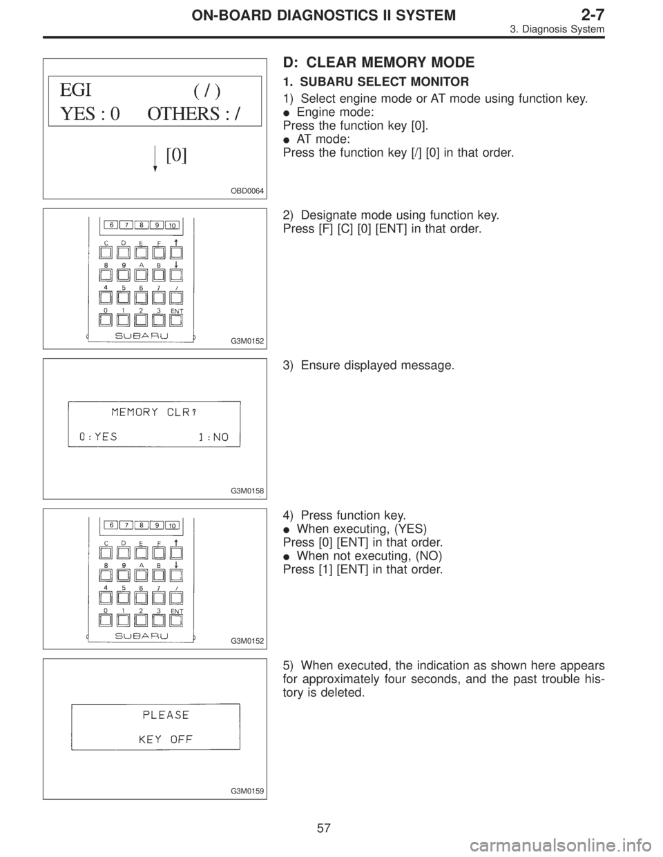
D: CLEAR MEMORY MODE
1. SUBARU SELECT MONITOR
1) Select engine mode or AT mode using function key.
�Engine mode:
Press the function key [0].
�AT mode:
Press the function key [/] [0] in that order.
G3M0152
2) Designate mode using function key.
Press [F] [C] [0] [ENT] in that order.
G3M0158
3) Ensure displayed message.
G3M0152
4) Press function key.
�When executing, (YES)
Press [0] [ENT] in that order.
�When not executing, (NO)
Press [1] [ENT] in that order.
G3M0159
5) When executed, the indication as shown here appears
for approximately four seconds, and the past trouble his-
tory is deleted.
57
2-7ON-BOARD DIAGNOSTICS II SYSTEM
3. Diagnosis System
Page 1267 of 2248
 Connect ST to Subaru select monitor cable.
ST 498357200 ADAPTER CABLE
OBD0006C
(2) Open the cover and co")
OBD0669A
�Using data link connector for Subaru select monitor and
OBD-II general scan tool:
(1) Connect ST to Subaru select monitor cable.
ST 498357200 ADAPTER CABLE
OBD0006C
(2) Open the cover and connect Subaru select monitor
to data link connector located in the lower portion of the
instrument panel (on the driver’s side), to the lower
cover.
CAUTION:
Do not connect scan tools except for Subaru select
monitor and OBD-II general scan tool.
OBD0060
6) Turn ignition switch ON (engine OFF) and Subaru
select monitor switch ON.
7) Start the engine.
NOTE:
�Ensure the selector lever is placed in the“P”position
before starting. (AT vehicles)
�Depress clutch pedal when starting the engine. (MT
vehicles)
8) Using the selector lever or shift lever, turn the“P”posi-
tion switch and the“N”position switch to ON.
9) Depress the brake pedal to turn the brake switch ON.
(AT vehicles)
10) Keep engine speed in the 2,500—3,000 rpm range
for 40 seconds.
NOTE:
On models without tachometer, use the Subaru select
monitor or tachometer (Secondary pickup type).
11) Place the selector lever or shift lever in the“D”posi-
tion (AT vehicles) or“1st”gear (MT vehicles) and drive the
vehicle at 5 to 10 km/h (3 to 6 MPH).
NOTE:
�On AWD vehicles, release the parking brake.
�The speed difference between front and rear wheels
may light either the ABS or the ABS/TCS warning light, but
this indicates no malfunctions. When engine control diag-
nosis is finished, perform the ABS or the ABS/TCS memory
clearance procedure of self-diagnosis system.
4-4a [T6C2] or 4-4b [T6C2] or [T9K0].>
61
2-7ON-BOARD DIAGNOSTICS II SYSTEM
3. Diagnosis System
Page 1268 of 2248
 Connect test mode connector at the lower side of the
inst")
OBD0005B
3. OBD-II GENERAL SCAN TOOL
After performing diagnostics and clearing the memory,
check for any remaining unresolved trouble data:
1) Connect test mode connector at the lower side of the
instrument panel (on the driver’s side), to the side of the
center console box.
OBD0006C
2) Open the cover and connect the OBD-II general scan
tool to its data link connector in the lower portion of the
instrument panel (on the driver’s side), to the lower cover.
CAUTION:
Do not connect the scan tools except for Subaru select
monitor and OBD-II general scan tool.
3) Start the engine.
NOTE:
�Ensure the selector lever is placed in the“P”position
before starting. (AT vehicles)
�Depress clutch pedal when starting the engine. (MT
vehicles)
4) Using the selector lever or shift lever, turn the“P”posi-
tion switch and the“N”position switch to ON.
5) Depress the brake pedal to turn the brake switch ON.
(AT vehicles)
6) Keep engine speed in the 2,500—3,000 rpm range for
40 seconds.
NOTE:
On models without tachometer, use the Subaru select
monitor or tachometer (Secondary pickup type).
7) Place the selector lever or shift lever in the“D”position
(AT vehicles) or“1st”gear (MT vehicles) and drive the
vehicle at 5 to 10 km/h (3 to 6 MPH).
NOTE:
�On AWD vehicles, release the parking brake.
�The speed difference between front and rear wheels
may light either the ABS or the ABS/TCS warning light, but
this indicates no malfunctions. When engine control diag-
nosis is finished, perform the ABS or the ABS/TCS memory
clearance procedure of self-diagnosis system.
4-4a [T6C2] or 4-4b [T6C2] or [T9K0].>
62
2-7ON-BOARD DIAGNOSTICS II SYSTEM
3. Diagnosis System
Page 1269 of 2248
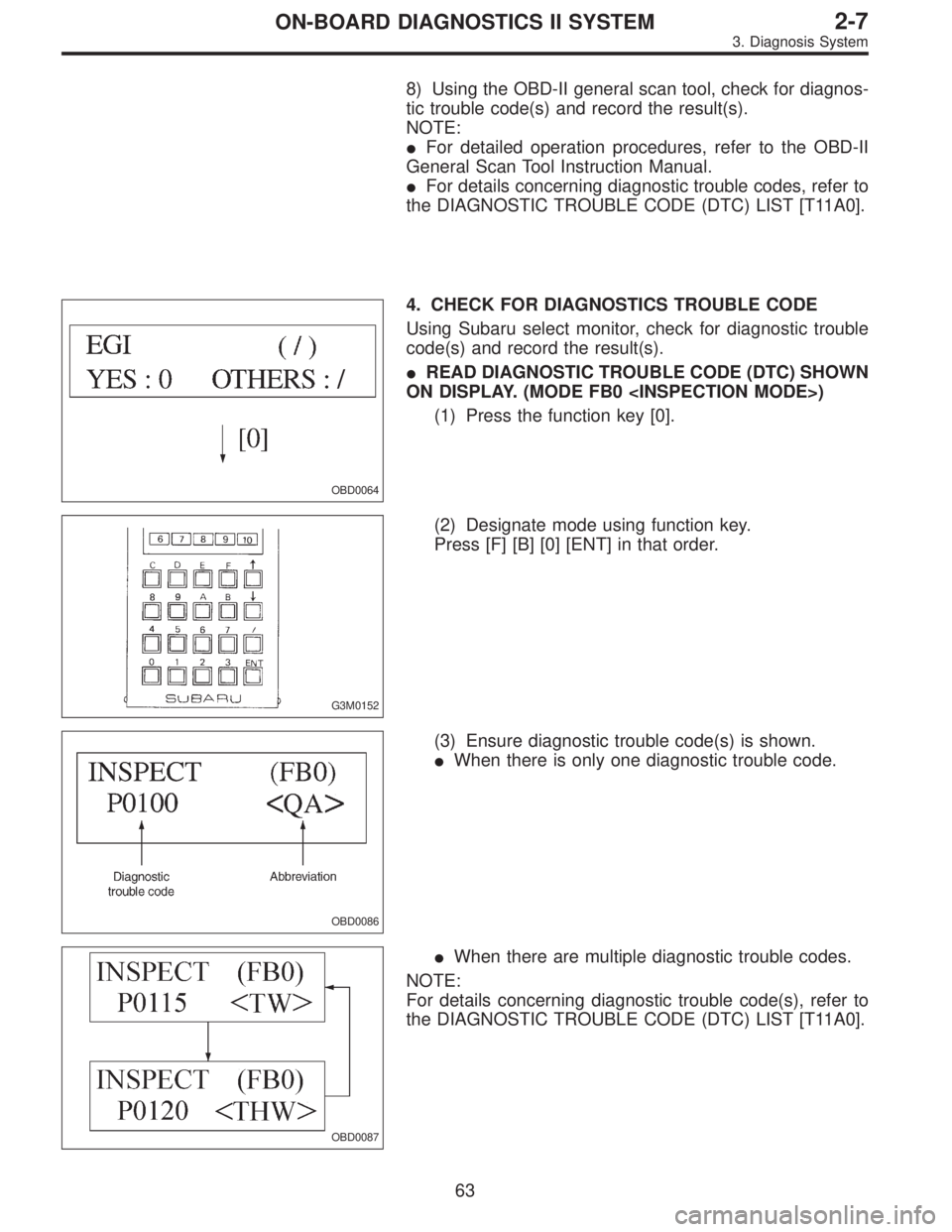
8) Using the OBD-II general scan tool, check for diagnos-
tic trouble code(s) and record the result(s).
NOTE:
�For detailed operation procedures, refer to the OBD-II
General Scan Tool Instruction Manual.
�For details concerning diagnostic trouble codes, refer to
the DIAGNOSTIC TROUBLE CODE (DTC) LIST [T11A0].
OBD0064
4. CHECK FOR DIAGNOSTICS TROUBLE CODE
Using Subaru select monitor, check for diagnostic trouble
code(s) and record the result(s).
�READ DIAGNOSTIC TROUBLE CODE (DTC) SHOWN
ON DISPLAY. (MODE FB0 )
(1) Press the function key [0].
G3M0152
(2) Designate mode using function key.
Press [F] [B] [0] [ENT] in that order.
OBD0086
(3) Ensure diagnostic trouble code(s) is shown.
�When there is only one diagnostic trouble code.
OBD0087
�When there are multiple diagnostic trouble codes.
NOTE:
For details concerning diagnostic trouble code(s), refer to
the DIAGNOSTIC TROUBLE CODE (DTC) LIST [T11A0].
63
2-7ON-BOARD DIAGNOSTICS II SYSTEM
3. Diagnosis System
Page 1428 of 2248
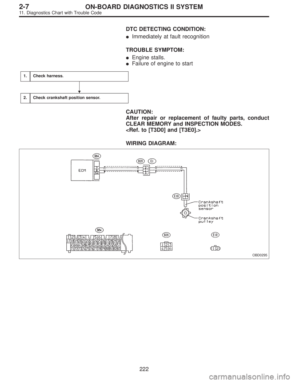
DTC DETECTING CONDITION:
�Immediately at fault recognition
TROUBLE SYMPTOM:
�Engine stalls.
�Failure of engine to start
1.Check harness.
2.Check crankshaft position sensor.
CAUTION:
After repair or replacement of faulty parts, conduct
CLEAR MEMORY and INSPECTION MODES.
WIRING DIAGRAM:
OBD0295
�
222
2-7ON-BOARD DIAGNOSTICS II SYSTEM
11. Diagnostics Chart with Trouble Code
Page 1440 of 2248

: Is there clogging in the gas outlets of intake
manifold or cylinder head, checking by
breathing into the outlets?
: Repair or replace intake manifold or cylinder
head. And go to
CONFIRMATION OF
ACTUAL DRIVING PATTERN.
: Replace EGR valve. And go toCONFIRMA-
TION OF ACTUAL DRIVING PATTERN.
CONFIRMATION OF ACTUAL DRIVING
PATTERN.
1) Conduct CLEAR MEMORY and INSPECTION MODES.
2) Connect Subaru select monitor to its data link connec-
tor.
3) Start and warm-up the engine until the radiator fan
makes one complete rotation. (All accessory switches are
OFF.)
4) Turn Subaru select monitor switch to ON.
5) Designate mode using function key.
Function mode: FA4
6) Drive at 55±3 MPH (88±5 km/h) until the LED No. 5 is
turned on.
NOTE:
Keep the throttle valve opening at the same degree, since
diagnosis will be interrupted when the opening varies.
Diagnosis starts in 190 seconds after starting engine and
takes 4 seconds.
Put the gear to“D”range for the diagnosis.
7) Designate mode using function key.
Function mode: FB0
8) Confirm the“No trouble”indication on Subaru select
monitor.
234
2-7ON-BOARD DIAGNOSTICS II SYSTEM
11. Diagnostics Chart with Trouble Code
Page 1540 of 2248
OBD0736A
1
CHECK OUTPUT SIGNAL FROM ECM.
1) Turn ignition switch to OFF.
2) Connect test mode connector at the lower portion of
instrument panel (on the driver’s side), to the side of the
center console box.
3) Turn ignition switch to ON.
OBD0674A
4) Measure voltage between ECM and body.
: Connector & terminal
(B84) No. 77—Body/10 V, or more and 1 V
or less at every 2 seconds
: Go to step 6.
: Go to next.
OBD0534A
: Connector & terminal
(B84) No. 88—Body/10 V, or more
: Go to step 5.
: Go to step 2.
2
CHECK POWER SUPPLY FOR RELAYS.
Turn ignition switch to OFF.
: Is the fuse in power supply circuit broken?
: Replace the fuse.
: Go to step 3.
OBD0535
3CHECK MAIN FAN RELAY 1, SUB FAN RELAY
1 AND MAIN FAN RELAY.
1) Remove main fan relay 1. (With A/C models only)
2) Measure resistance between main fan relay 1 termi-
nals.
: Terminal
No. 1—No. 3/97±10Ω
: Go to next step.
: Replace main fan relay 1.
334
2-7ON-BOARD DIAGNOSTICS II SYSTEM
11. Diagnostics Chart with Trouble Code
 Turn ignition switch to OFF.
2) Connect test mode connector at the lower portion of
instrument panel (on the driver’s side), to the side of the
center con")