Page 681 of 2248
B4M0557A
4) Temporarily install clamp E on pipes C and D.
CAUTION:
Ensure that the letter“8”on each clamp side are
diagonally opposite each other as shown in the figure.
5) Tighten clamp E firmly.
Tightening torque:
7.4±2.0 N⋅m (0.75±0.20 kg-m, 5.4±1.4 ft-lb)
6) Tighten joint nut.
Tightening torque:
15±5 N⋅m (1.5±0.5 kg-m, 10.8±3.6 ft-lb)
G4M0099
7) Connect pipes A and B to four pipe joints of gearbox.
Connect upper pipe B first, and lower pipe A second.
Tightening torque:
13±3 N⋅m (1.3±0.3 kg-m, 9.4±2.2 ft-lb)
8) Install jack-up plate.
9) Connect battery minus terminal.
10) Feed the specified fluid and discharge air.
NOTE:
Never start the engine before feeding the fluid; otherwise
vane pump might be seized up.
65
4-3SERVICE PROCEDURE
7. Pipe Assembly (Power Steering System) [LHD model]
Page 686 of 2248
B4M0671A
7) Connect pipes A and B to four pipe joints of gearbox.
Connect upper pipe A first, and lower pipe B second.
Tightening torque:
13±3 N⋅m (1.3±0.3 kg-m, 9.4±2.2 ft-lb)
8) Install jack-up plate.
9) Connect battery negative terminal.
10) Feed the specified fluid and discharge air.
NOTE:
Never start the engine before feeding the fluid; otherwise
vane pump might be seized up.
70
4-3SERVICE PROCEDURE
8. Pipe Assembly (Power Steering System) [RHD model]
Page 726 of 2248
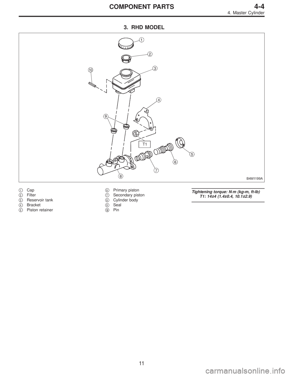
3. RHD MODEL
B4M1199A
�1Cap
�
2Filter
�
3Reservoir tank
�
4Bracket
�
5Piston retainer�
6Primary piston
�
7Secondary piston
�
8Cylinder body
�
9Seal
�
10Pin
Tightening torque: N⋅m (kg-m, ft-lb)
T1: 14±4 (1.4±0.4, 10.1±2.9)
11
4-4COMPONENT PARTS
4. Master Cylinder
Page 772 of 2248

A: GENERAL RULES FOR EFFECTIVE
BLEEDING
1) Start with the brakes (wheels) connecting to the sec-
ondary chamber of the master cylinder.
2) The time interval betwee")
11. Air Bleeding (Without TCS model)
A: GENERAL RULES FOR EFFECTIVE
BLEEDING
1) Start with the brakes (wheels) connecting to the sec-
ondary chamber of the master cylinder.
2) The time interval between two brake pedal operations
(from the time when the pedal is released to the time when
it is depressed another time) shall be approximately 3 sec-
onds.
3) The air bleeder on each brake shall be released for 1
to 2 seconds.
B: BLEEDING PROCEDURE
CAUTION:
�The FMVSS No. 116, fresh DOT3 or 4 brake fluid
must be used.
�Cover bleeder with waste cloth, when loosening it,
to prevent brake fluid from being splashed over sur-
rounding parts.
�Avoid mixing different brands of brake fluid to pre-
vent degrading the quality of the fluid.
�Be careful not to allow dirt or dust to get into the
reservoir tank.
NOTE:
�During bleeding operation, keep the brake reserve tank
filled with brake fluid to eliminate entry of air.
�Brake pedal operating must be very slow.
�For convenience and safety, it is advisable to have two
man working.
G4M0434
G4M0435
1) Make sure that there is no leak from joints and connec-
tions of the brake system.
2) Fit one end of vinyl tube into the air bleeder and put the
other end into a brake fluid container.
3) Slowly depress the brake pedal and keep it depressed.
Then, open the air bleeder to discharge air together with
the fluid.
Release air bleeder for 1 to 2 seconds.
Next, with the bleeder closed, slowly release the brake
pedal.
Repeat these steps until there are no more air bubbles in
the vinyl tube.
Allow 3 to 4 seconds between two brake pedal operations.
CAUTION:
Cover bleeder with waste cloth, when loosening it, to
prevent brake fluid from being splashed over sur-
rounding parts.
NOTE:
Brake pedal operating must be very slow.
4) Tighten air bleeder securely when no air bubbles are
visible.
55
4-4SERVICE PROCEDURE
11. Air Bleeding (Without TCS model)
Page 773 of 2248

5) Perform these steps for the brakes connecting to the
secondary chamber of master cylinder, first, and then for
the ones con")
Air bleeder tightening torque:
8±1 N⋅m (0.8±0.1 kg-m, 5.8±0.7 ft-lb)
5) Perform these steps for the brakes connecting to the
secondary chamber of master cylinder, first, and then for
the ones connecting to primary chamber. With all proce-
dures completed, fully depress the brake pedal and keep
it in that position for approximately 20 seconds to make
sure that there is no leak evident in the entire system.
G4M0436
6) Perform sequence control. (With ABS model)
[W15C1].>
7) Check the pedal stroke.
While the engine is idling, depress the brake pedal with a
490 N (50 kg, 110 lb) load and measure the distance
between the brake pedal and steering wheel. With the
brake pedal released, measure the distance between the
pedal and steering wheel again. The difference between
the two measurements must be more than specified.
Specified pedal stroke:
Without ABS
90 mm (3.54 in)
With ABS
95 mm (3.74 in)
When depressing brake pedal with a 490 N (50 kg,
110 lb) load.
(1) Models without ABS
If the distance is more than specifications, there is a
possibility that air is in the brake line. Bleed air from the
brake line.
(2) Models with ABS
If the distance is more than specifications, there is a
possibility air is in the inside of the hydraulic unit.
Therefore, air must be bled from the inside of the
hydraulic unit to the brake pipes in accordance with the
bleeding sequence control.
8) Add brake fluid to the required level (MAX. level) of
reserve tank.
9) As a final step, test run the vehicle at low speed and
apply brakes relatively hard 2 to 3 times to ensure that
brakes provide normal braking action on all four wheels
without dragging and uneven braking.
56
4-4SERVICE PROCEDURE
11. Air Bleeding (Without TCS model)
Page 797 of 2248

A: RULES FOR EFFECTIVE BLEEDING
1) Pressure is not applied to suction pipe by depressing
brake pedal. When any of the following are performed,
bleed air from suction")
19. Air Bleeding (With TCS model)
A: RULES FOR EFFECTIVE BLEEDING
1) Pressure is not applied to suction pipe by depressing
brake pedal. When any of the following are performed,
bleed air from suction pipe by air bleeding control opera-
tion.
NOTE:
For TCS vehicle, suction pipe is installed between master
cylinder and hydraulic unit to allow flow of brake fluid
between them during ABS and TCS operation.
(1) When brake pipe is disconnected from master cyl-
inder.
(2) When brake pipe between hydraulic unit and mas-
ter cylinder is disconnected.
(3) When fluid is emptied from reservoir tank.
2) The time interval between two brake pedal operations
(from the time when the pedal is released to the time when
it is depressed another time) shall be approximately 3 sec-
onds.
3) The air bleeder on each brake shall be released for 1
to 2 seconds.
B: BLEEDING PROCEDURE WITH AIR
BLEEDING CONTROL
1. BLEEDING PROCEDURE
CAUTION:
�The FMVSS No. 116, fresh DOT3 or 4 brake fluid
must be used.
�Cover bleeder with waste cloth, when loosening it,
to prevent brake fluid from being splashed over sur-
rounding parts.
�Avoid mixing different brands of brake fluid to pre-
vent degrading the quality of the fluid.
�Be careful not to allow dirt or dust to get into the
reservoir tank.
�During bleeding operation, keep the brake reserve
tank filled with brake fluid to eliminate entry of air.
NOTE:
�Brake pedal operating must be very slow.
�For convenience and safety, it is advisable to have two
man working.
G4M0434
1) Start air bleeding control operation.
[W19D0].>
2) Make sure that there is no leak from joints and connec-
tions of the brake system.
3) Bleed air through front RH caliper by operating brake
pedal.
(1) Fit one end of vinyl tube into the air bleeder and put
the other end into a brake fluid container.
78
4-4SERVICE PROCEDURE
19. Air Bleeding (With TCS model)
Page 798 of 2248
 Slowly depress the brake pedal and keep it
depressed. Then, open the air bleeder to discharge air
together with the fluid.
Release air bleeder for 1 to 2 seconds.
Next, with the bleeder closed, sl")
(2) Slowly depress the brake pedal and keep it
depressed. Then, open the air bleeder to discharge air
together with the fluid.
Release air bleeder for 1 to 2 seconds.
Next, with the bleeder closed, slowly release the brake
pedal.
Repeat these steps until there are no more air bubbles
in the vinyl tube.
Allow 3 to 4 seconds between two brake pedal opera-
tions.
CAUTION:
Cover bleeder with waste cloth, when loosening it, to
prevent brake fluid from being splashed over sur-
rounding parts.
NOTE:
Brake pedal operating must be very slow.
4) Bleed air from suction pipe through front RH caliper.
(1) Open the air bleeder.
(2) Keep pressing TCS OFF switch for 20 seconds or
more.
NOTE:
Ensure no air comes out from air bleeder.
(3) Close the air bleeder.
5) Bleed air through front LH caliper by operating brake
pedal. This is the same procedure as step 3).
6) Bleed air from suction pipe through front LH caliper.
This is the same procedure as step 4).
7) Bleed air through front RH and LH calipers by operat-
ing brake pedal. This is the same procedure as step 3).
Repeat steps 3) to 7) until air does no longer comes out.
8) Tighten air bleeders securely when bubbles are visible.
Air bleeder tightening torque:
8±1 N⋅m (0.8±0.1 kg-m, 5.8±0.7 ft-lb)
9) Bleed air through rear LH and RH caliper by operating
brake pedal. This is the same procedure as step 3).
10) Tighten air bleeders securely when bubbles are vis-
ible.
Air bleeder tightening torque:
8±1 N⋅m (0.8±0.1 kg-m, 5.8±0.7 ft-lb)
79
4-4SERVICE PROCEDURE
19. Air Bleeding (With TCS model)
Page 799 of 2248
 Operate FRO (Front Right Outlet) valve and RLO
(Rear Left Outlet) valve to bleed air from hydraulic unit
outlet circuit.
(1) Press TCS OFF switch while depressing brake
pedal.
(2) Make sure ABS wa")
11) Operate FRO (Front Right Outlet) valve and RLO
(Rear Left Outlet) valve to bleed air from hydraulic unit
outlet circuit.
(1) Press TCS OFF switch while depressing brake
pedal.
(2) Make sure ABS warning light illuminates.
(3) Repeatedly depress and release brake pedal 10
times or more while pressing TCS OFF switch.
NOTE:
�Air comes out from reservoir tank.
12) Operate FLO (Front Left Outlet) valve and RRO (Rear
Right Outlet) valve to bleed air from hydraulic unit outlet
circuit.
(1) Press TCS OFF switch while depressing brake
pedal.
(2) Make sure TCS warning light illuminates.
(3) Repeatedly depress and release brake pedal 10
times or more while pressing TCS OFF switch.
NOTE:
�Air comes out from reservoir tank.
�The operations in steps 11) and 12) above can be
switched with each other by operating brake pedal (stop
light switch) while pressing TCS OFF switch.
�Repeat procedures 11) and 12) until air no longer comes
out of reservoir tank.
13) Perform these steps for the brakes connecting to the
secondary chamber of master cylinder, first, and then for
the ones connecting to primary chamber. With all proce-
dures completed, fully depress the brake pedal and keep
it in that position for approximately 20 seconds to make
sure that there is no leak evident in the entire system.
14) Turn ignition switch OFF.
15) Perform TCS sequence control.
80
4-4SERVICE PROCEDURE
19. Air Bleeding (With TCS model)
 Temporarily install clamp E on pipes C and D.
CAUTION:
Ensure that the letter“8”on each clamp side are
diagonally opposite each other as shown in the figure.
5) Tighten clamp E firmly.")
 Connect pipes A and B to four pipe joints of gearbox.
Connect upper pipe A first, and lower pipe B second.
Tightening torque:
13±3 N⋅m (1.3±0.3 kg-m, 9.4±2.2 ft-lb)
8) Install jack-up")