Page 1543 of 2248
 Turn ignition switch to OFF.
2) Remove main fan relay 1 and sub fan relay 1. (with A/C
models)
Remove main fan relay. (without A/C models)
3) Disconnect test mod")
OBD0534A
5
CHECK HARNESS CONNECTOR.
1) Turn ignition switch to OFF.
2) Remove main fan relay 1 and sub fan relay 1. (with A/C
models)
Remove main fan relay. (without A/C models)
3) Disconnect test mode connector.
4) Turn ignition switch to ON.
5) Measure voltage between ECM and body.
: Connector & terminal
(B84) No. 88—Body / 10 V, or more
: Repair short circuit of harness and replace ECM.
: Go to next.
: Is there poor contact in ECM connector?
: Repair poor contact in ECM connector.
: Replace ECM.
OBD0674A
6
CHECK MONITOR LINE.
1) Turn ignition switch to OFF.
2) Connect test mode connector.
3) Turn ignition switch to ON.
4) Measure voltage between ECM and body.
: Connector & terminal
(B84) No. 77—Body / 10 V, or more and 1
V, or less at every 2
seconds.
: Repair poor contact in ECM connector.
: Repair open circuit of harness between ECM con-
nector and sub fan relay 1 (with A/C models) or
main fan relay (without A/C models).
337
2-7ON-BOARD DIAGNOSTICS II SYSTEM
11. Diagnostics Chart with Trouble Code
Page 1632 of 2248

5. Control Module I/O Signal
1. I/O SIGNAL VOLTAGE
G4M0685
ContentsTerminal
No.Ignition
switch ON,
engine
OFFInput/output signals
Measured value Measuring conditions
A.B.S.
sensorFront left wheel 22
0 V 0.12—1V�No. 22—No. 4
(When it is 10 Hz.)
GND 4
Front right wheel 23
0 V 0.12—1V�No. 23—No. 21
(When it is 10 Hz.)
GND 21
Rear left wheel 8
0 V 0.12—1V�No. 8—No. 9
(When it is 10 Hz.)
GND 9
Rear right wheel 24
0 V 0.12—1V�No. 24—No. 26
(When it is 10 Hz.)
GND 26
G sensor (AWD MT model) 13 10—12 V 0 V When slanting about 14°—21.3°(θ)
Diagnosis connector30
—— —
31
Stop light switch 25 0 V 10—12 V When brake pedal is depressed.
Motor monitoring 14 0 V 10—12 V When motor operates.
Valve power supply monitoring 32 10—12 V 10—12 V Ignition switch ON*1
Hydraulic
control
unitSolenoidFront left
wheel210—12 V 0 V
When solenoid is energized to
produce output. Front right
wheel35 10—12 V 0 V
Rear wheel 18 10—12 V 0 V
Valve relay coil 27 0 V 0 V Ignition switch ON*2
Motor relay coil 28 10—12 V 0 VWhen motor operates to produce
output.
Warning light 29 10—12 V 10—12 V Ignition switch ON*3
Power
supplyIgnition 1 10—12 V 10—12 V Ignition switch ON
Relay coil (valve,
motor, etc.)17 10—12 V 10—12 V Ignition switch ON
Grounding line10 0V 0V—
20 0V 0V—
34 0V 0V—
*1: When ignition switch is OFF or the A.B.S. system is inactive: 0 V
*2: When ignition switch is OFF or the A.B.S. system is inactive: 10—12 V
*3: When ignition switch is OFF or the A.B.S. system is inactive, or during 1.5 seconds from ignition switch ON: 0 V
5
4-4aBRAKES
5. Control Module I/O Signal
Page 1635 of 2248

or more for at least 20 seconds. If a problem is found, the
A.B.S")
B: INSPECTION MODE
The on-board diagnosis system is designed to detect prob-
lems after the vehicle has been driven at 10 km/h (6 MPH)
or more for at least 20 seconds. If a problem is found, the
A.B.S. warning light will illuminate to inform the driver of the
occurrence of a problem. When the warning light is on, the
A.B.S. system will be inactive and the normal braking func-
tion will work. It is possible for a maximum of three trouble
codes to be stored in memory until cleared.
B4M0082A
C: TROUBLE CODES
When on-board diagnosis of the A.B.S. control module
detects a problem, the information (up to a maximum of
three) will be stored in the EEP ROM as a trouble code.
When there are more than three, the most recent three will
be stored. (Stored codes will stay in memory until they are
cleared.)
1. CALLING UP A TROUBLE CODE
1) Take out diagnosis connector from side of driver’s seat
heater unit.
2) Turn ignition switch OFF.
3) Connect diagnosis connector terminal 6 (terminal L) to
diagnosis terminal.
4) Turn ignition switch ON.
5) A.B.S. warning light is set in the diagnostic mode and
blinks to identify trouble code.
6) After the start code (11) is shown, the trouble codes will
be shown in order of the last information first.
These repeat for a maximum of 5 minutes.
NOTE:
When there are no trouble codes in memory, only the start
code (11) is shown.
B4M0232A
8
4-4aBRAKES
6. Diagnostics Chart for On-board Diagnosis System
Page 1677 of 2248

8. General Diagnostics Chart
A: VIBRATING PEDAL AND NOISE
Depress brake pedal
abruptly to check if
such problems occur
while A.B.S. is in
operation.
Ye s
No�Normal
When do problems
occur?�When engine
starts.�Check using on-board diagnosis system accord-
ing to trouble code.
�Before vehicle
attains initial 10
km/h (6 MPH)
speed immediately
after engine starts.�Do problems stop
within 5 seconds?
No
�Ye s
Normal
Go to�1.
�
�
Only when vehicle
is being driven.
�
Brake pedal is
released.
�A.B.S. sometimes operates when variations in
wheel rotating speed occur:
a. During shifts. (AT model: Band brake locks
wheels. MT model: Abrupt engine brake opera-
tion locks wheels.)
b. During clutch operation. (Engine brake opera-
tion locks wheels.)
c. When riding over an obstacle.
d. During rough-road driving.
e. During“U”turns. (“Slip”signal often is emit-
ted.)
f. When wheels are stuck.
�Except for those out-
lined above.�Go to�1.
�
Brake pedal is
depressed.
�A.B.S. sometimes
operates except when
brake pedal is
depressed abruptly:
a. Low“µ”roads.
b.“U”turns during
high-speed operations.
c. During rough-road
driving.
d. When tire chains
are installed.
e. Use of improper
tires.
f. Excessive free play
of wheels and associ-
ated parts.�Check tire pres-
sure.
(Premature wear
may occur if tires
other than those
specified are
used.)
a. Use specified
tires.
b. Adjust tire pres-
sure evenly.
c. Use of an
“emergency”tire.
d. Check wheels
and associated
parts if excessive
free play is noted.
�1�Except for those
outlined above.�Go to�1.
�
50
4-4aBRAKES
8. General Diagnostics Chart
Page 1684 of 2248
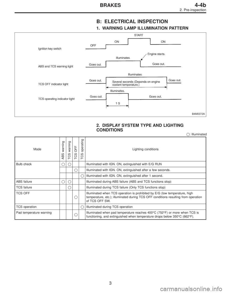
B: ELECTRICAL INSPECTION
1. WARNING LAMP ILLUMINATION PATTERN
B4M0372A
2. DISPLAY SYSTEM TYPE AND LIGHTING
CONDITIONS
�: Illuminated
Mode
ABS warning
TCS warning
TCS OFF
TCS operating
Lighting conditions
Bulb check��Illuminated with IGN. ON, extinguished with E/G RUN
�Illuminated with IGN. ON, extinguished after a few seconds.
�Illuminated with IGN. ON, extinguished after 1 second.
ABS failure��Illuminated during ABS failure (ABS and TCS functions stop)
TCS failure�Illuminated during TCS failure (Only TCS functions stop)
TCS OFF
�Illuminated when TCS operation is prohibited by E/G (low temperature, high
temperature, etc.); illuminated during TCS OFF conditions resulting from operation
of TCS OFF SW.
TCS operation�Illuminated during TCS operation
Pad temperature warning
�Illuminated when pad temperature reaches 400°C (752°F) or more when TCS is
functioning, and extinguished when temperature drops below 350°C (662°F).
3
4-4bBRAKES
2. Pre-inspection
Page 1691 of 2248

3. LIST OF ABS/TCS ON-BOARD DIAGNOSTICS
FUNCTIONS
Trouble codeDiagnostic items
Detection timingIndicator
light ON
Parts concerned
At initial checking
Under no control
Under ABS control
Under TCS control
In diagnostic mode
ABS warning light
TCS warning light
TCS OFF indicator light
21 FR
23 FL
25 RR
27 RLDetection of fault in ABS sensor hardware
���� ��—ABS sensor (ABS/TCS C/M)
22 FR
24 FL
26 RR
28 RLDetection of fault in ABS sensor software
��� ��—ABS sensor (ABS/TCS C/M)
��� ��—ABS sensor harness circuit (ABS/TCS C/M)
Detection of fault in ABS sensor software
���—ABS sensor and solenoid valve (ABS/TCS C/M)
���—ABS sensor (ABS/TCS C/M)
Detection of fault in sensor software
���� ��—ABS sensor (ABS/TCS C/M)
31 FRI
32 FRO
33 FLI
34 FLO
35 RRI
36 RRO
37 RLI
38 RLO
61 TCS1
62 TCS2Abnormal valve
����*
���—Solenoid valve (ABS/TCS C/M)
41 Abnormal ABS/TCS C/M
���� ��—ABS/TCS C/M
42 Abnormal line voltage
�������—Power source operating environment (ABS/TCS C/M)
—Power source voltage drop
���� ��—
������—
*: Except when trouble code is being displayed.
10
4-4bBRAKES
5. Control Module I/O Signal
Page 1694 of 2248
6. Diagnostics Chart for On-board
Diagnosis System
A: BASIC DIAGNOSTICS PROCEDURE
TROUBLE OCCURS.
Ask the customer when and how the
trouble occurred using interview
check list.
PRE-INSPECTION
INSPECTION MODE
CALLING UP A TROUBLE CODE.
�No trouble code is readable.
�
Inspection using Diagnostic Chart for
Warning Light Failure.
Record all trouble codes.
Trouble codes
are issued.
�Only the start code is issued.
Inspection using General Diagnostics
Chart
Perform diagnostics in accordance with trouble code.
Trouble code
designated.
�
Repair.�
Clear memory.
INSPECTION MODE
CALLING UP A TROUBLE CODE.
Only the start code is issued.
CONFIRMATION TEST
END
NOTE:
�To check harness for broken wires or short circuits,
shake it while holding it or the connector.
�When TCS warning light illuminates, read and record
trouble code indicated by TCS warning light.
�
�
�
�
�
�
�
�
�
�
�
�
13
4-4bBRAKES
6. Diagnostics Chart for On-board Diagnosis System
Page 1773 of 2248
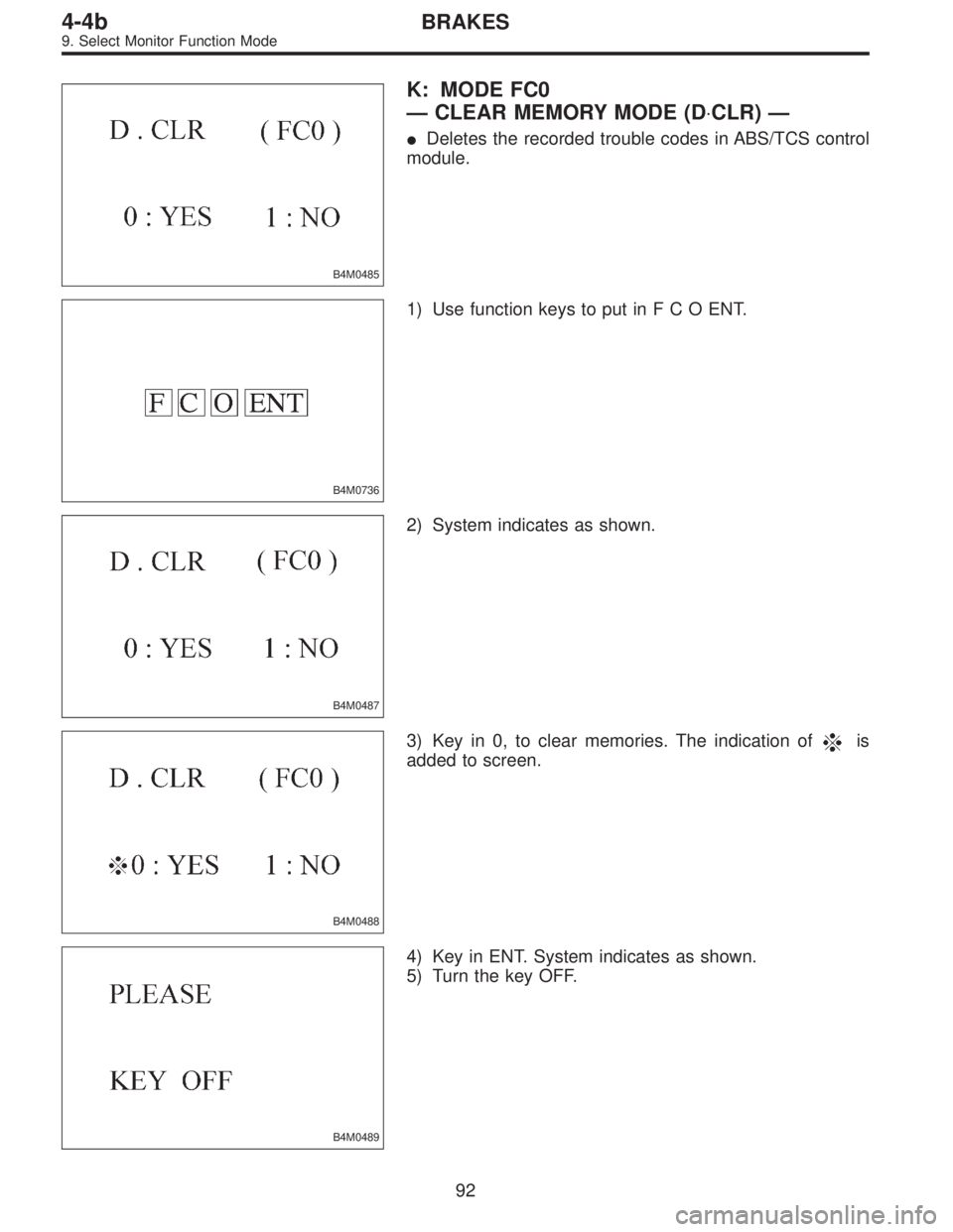
B4M0485
K: MODE FC0
—CLEAR MEMORY MODE (D⋅CLR)—
�Deletes the recorded trouble codes in ABS/TCS control
module.
B4M0736
1) Use function keys to put inFCOENT.
B4M0487
2) System indicates as shown.
B4M0488
3) Key in 0, to clear memories. The indication ofis
added to screen.
B4M0489
4) Key in ENT. System indicates as shown.
5) Turn the key OFF.
92
4-4bBRAKES
9. Select Monitor Function Mode
![SUBARU LEGACY 1995 Service Repair Manual 6. Diagnostics Chart for On-board
Diagnosis System
A: BASIC DIAGNOSTICS PROCEDURE
TROUBLE OCCURS.
Ask the customer when and how the
trouble occurred using interview
check list. <Ref. to 4-4b [T6B0].>](/manual-img/17/57432/w960_57432-1693.png "SUBARU LEGACY 1995 Service Repair Manual 6. Diagnostics Chart for On-board
Diagnosis System
A: BASIC DIAGNOSTICS PROCEDURE
TROUBLE OCCURS.
Ask the customer when and how the
trouble occurred using interview
check list. <Ref. to 4-4b [T6B0].>")