Page 801 of 2248

3. CONDITIONS FOR COMPLETION OF AIR
BLEEDING CONTROL
When any of the following conditions occurs, ABS and TCS
warning lights illuminate. Air bleeding control stops, while
the ABS and TCS function will then stop. The brake sys-
tem functions as a conventional brake system.
1) When the speed of at least one wheel reaches 10 km/h
(6 MPH).
2) When terminal No. 4 is separated from diagnosis termi-
nal. (When select monitor is not used.)
3) When pump motor remains ON for two minutes.
4) When TCS valve remains open for two minutes.
5) When outlet valve remains closed for two minutes.
6) When malfunction is detected.
NOTE:
When a malfunction is detected the air bleeding operation
stops and the trouble codes are stored in memory.
B4M0082C
C: AIR BLEEDING CONTROL WITH
DIAGNOSIS CONNECTOR
1) Connect diagnosis terminals to terminal No. 4 of the
diagnosis connector beside driver’s seat heater unit.
B4M0621A
2) Start the engine while pushing TCS OFF switch.
NOTE:
Keep the TCS OFF switch depressed even after the engine
has started.
3) After ABS and TCS warning lights go out, depress
brake pedal within 0.5 seconds.
4) After ensuring TCS ON indicator illuminates, release
TCS OFF switch and brake pedal.
5) Air bleeding control operation starts.
82
4-4SERVICE PROCEDURE
19. Air Bleeding (With TCS model)
Page 808 of 2248
 Under the ABS sequence control, after the hydraulic
unit solenoid valve is driven, the operation of the hydraulic
unit can be checked by means of the brake tester or pres-
s")
D: ABS SEQUENCE CONTROL
1) Under the ABS sequence control, after the hydraulic
unit solenoid valve is driven, the operation of the hydraulic
unit can be checked by means of the brake tester or pres-
sure gauge.
2) ABS sequence control can be started by diagnosis con-
nector or select monitor.
B4M0082C
1. OPERATIONAL GUIDELINES OF THE ABS
SEQUENCE CONTROL WITH DIAGNOSIS
CONNECTOR
1) Connect diagnosis terminals to terminal No. 4 of the
diagnosis connector beside driver’s seat heater unit.
2) Ignition switch is turned to ON.
3) Make sure only the start code (code 11) is shown in
normal condition.
NOTE:
When trouble codes are stored in memory, repair the faulty
parts.
4) Set the speed of all wheels at 10 km/h (6 MPH) or less.
5) Turn ignition switch OFF.
6) Within 0.5 seconds after the ABS and TCS warning
lights go out, depress the brake pedal and hold it immedi-
ately after engine starts.
NOTE:
�When the ignition switch is set to on, the brake pedal
must not be depressed.
�Engine must operate.
�If brake pedal is not depressed within 0.5 seconds after
ABS and TCS warning lights go out, the trouble code mode
comes on.
7) After completion of ABS sequence control, turn ignition
switch OFF.
2. OPERATIONAL GUIDELINES OF THE ABS
SEQUENCE CONTROL WITH SELECT MONITOR
1) Connect select monitor to data link connector beside
driver’s seat heater unit.
2) Engine starts.
3) Put select monitor to TCS mode.
4) put select monitor to FBI mode. Make sure code 11 is
indicated.
NOTE:
When trouble codes are stored in memory, repair the faulty
parts.
89
4-4SERVICE PROCEDURE
20. Hydraulic Unit for ABS/TCS System
Page 814 of 2248
 Under the TCS sequence control, after the hydraulic
unit solenoid valve is driven, the operation of the hydraulic
unit can be checked by means of the brake tester or pres-
s")
F: TCS SEQUENCE CONTROL
1) Under the TCS sequence control, after the hydraulic
unit solenoid valve is driven, the operation of the hydraulic
unit can be checked by means of the brake tester or pres-
sure gauge.
2) TCS sequence control can be started by diagnosis con-
nector or select monitor.
B4M0082C
1. OPERATIONAL GUIDELINES OF THE TCS
SEQUENCE CONTROL WITH DIAGNOSIS
CONNECTOR
1) Connect diagnosis terminals to terminal No. 4 of the
diagnosis connector beside driver seat heater unit.
2) Ignition switch is turned to ON.
3) Make sure only the start code (code 11) is shown in
normal condition.
NOTE:
When trouble codes are stored in memory, repair the faulty
parts.
4) Set the speed of all wheels at 10 km/h (6 MPH) or less.
5) Turn ignition switch OFF.
6) Start engine, and within 0.5 seconds after the ABS
warning light and TCS warning light go out, press TCS OFF
switch. Within 1.0 second thereafter, release and press the
switch again. Then, keep the switch pressed.
NOTE:
�When the TCS sequence control is set to on, the brake
pedal must not be depressed.
�Engine must operate.
�When TCS OFF switch is not depressed within 0.5 sec-
onds after ABS and TCS warning lights turn off, the trouble
code mode comes on.
7) After completion of TCS sequence control, turn ignition
switch OFF.
95
4-4SERVICE PROCEDURE
20. Hydraulic Unit for ABS/TCS System
Page 1009 of 2248
 Installation of glass
(1) Hold glass with rubber suction cups.
(2) Mount glass on body with matching pin aligned.
(3) Stick them fast by pressing all sides lightly.
G5M0496
10) Installation")
G5M0409
9) Installation of glass
(1) Hold glass with rubber suction cups.
(2) Mount glass on body with matching pin aligned.
(3) Stick them fast by pressing all sides lightly.
G5M0496
10) Installation of molding
(1) Remove adhesive overflowing from outside of
glass until it becomes level with outer height of glass.
Then, add adhesive to portions that need it, and clean
with alcohol or white gasoline.
(2) Install front side molding.
CAUTION:
Do not open and close door after moldings have been
installed. When opening and closing door for unavoid-
able reason, lower door glass and gently move door.
11) Water leakage test
Test for water leakage about one hour after installation.
CAUTION:
�Move vehicle very gently.
�Do not squirt strong hose stream on vehicle.
12) Spontaneous drying
After completing all operations, leave vehicle alone for 24
hours.
CAUTION:
When delivering vehicle to user, tell him that vehicle
should not be subjected to heavy shocks for at least
three days.
13) Install cowl panel and wiper arm.
6. Rear Window Glass
A: REMOVAL
1. 4 DOOR MODEL
1) Disconnect connector from rear defogger terminal.
2) Remove glass in the same manner as in windshield.
34
5-2SERVICE PROCEDURE
5. Windshield - 6. Rear Window Glass
Page 1010 of 2248
 Installation of glass
(1) Hold glass with rubber suction cups.
(2) Mount glass on body with matching pin aligned.
(3) Stick them fast by pressing all sides lightly.
G5M0496
10) Installation")
G5M0409
9) Installation of glass
(1) Hold glass with rubber suction cups.
(2) Mount glass on body with matching pin aligned.
(3) Stick them fast by pressing all sides lightly.
G5M0496
10) Installation of molding
(1) Remove adhesive overflowing from outside of
glass until it becomes level with outer height of glass.
Then, add adhesive to portions that need it, and clean
with alcohol or white gasoline.
(2) Install front side molding.
CAUTION:
Do not open and close door after moldings have been
installed. When opening and closing door for unavoid-
able reason, lower door glass and gently move door.
11) Water leakage test
Test for water leakage about one hour after installation.
CAUTION:
�Move vehicle very gently.
�Do not squirt strong hose stream on vehicle.
12) Spontaneous drying
After completing all operations, leave vehicle alone for 24
hours.
CAUTION:
When delivering vehicle to user, tell him that vehicle
should not be subjected to heavy shocks for at least
three days.
13) Install cowl panel and wiper arm.
6. Rear Window Glass
A: REMOVAL
1. 4 DOOR MODEL
1) Disconnect connector from rear defogger terminal.
2) Remove glass in the same manner as in windshield.
34
5-2SERVICE PROCEDURE
5. Windshield - 6. Rear Window Glass
Page 1067 of 2248

1. Engine Electrical
A: SPECIFICATIONS
Item Designation
StarterType Reduction type
ModelMT
TN128000-8311AT
TN128000-8321
Manufacturer NIPPONDENSO TENNESSEE
Voltage and output 12 V — 1.0 kW 12 V — 1.4 kW
Direction of rotation Counterclockwise (when observed from pinion)
Number of pinion teeth 8 9
No-load
characteristicsVoltage 11 V
Current 90 A or less
Rotating
speed3,000 rpm or more 2,900 rpm or more
Load
characteristicsVoltage 8 V
Current 280 A or less 370 A or less
Torque 9.8 N⋅m (1.0 kg-m, 7.2 ft-lb) 13.7 N⋅m (1.4 kg-m, 10.1 ft-lb)
Rotating
speed900 rpm or more 880 rpm or more
Lock
characteristicsVoltage 5 V
Current 800 A or less 1,050 A or less
Torque 27.5 N⋅m (2.8 kg-m, 20.3 ft-lb) or more
GeneratorType Rotating-field three-phase type, Voltage regulator built-in type
Model LR185-701H
Manufacturer HITACHI AUTOMOTIVE PRODUCTS
Voltage and output 12 V — 85 A
Polarity on ground side Negative
Rotating direction Clockwise (when observed from pulley side)
Armature connection 3-phase Y-type
Output current1,500 rpm — 35 A or more
2,500 rpm — 62 A or more
5,000 rpm — 82 A or more
Regulated voltage 14.5
+0.3
�0.4V [20°C (68°F)]
Ignition
coilModel F-569-01R
Manufacturer Diamond
Primary coil resistance 0.69Ω±10%
Secondary coil resistance 21.0 kΩ±15%
Insulation resistance between
primary terminal and caseMore than 10 MΩ
Spark
plugType and manufacturerRC10YC4 .......... CHAMPION
Alternate
(BKR6E-11 .......... NGK
K20PR-U11 .......... NIPPONDENSO)
Thread size mm 14, P = 1.25
Spark gap mm (in) 1.0 — 1.1 (0.039 — 0.043)
2
6-1SPECIFICATIONS AND SERVICE DATA
1. Engine Electrical
Page 1164 of 2248
 Within 30 seconds after the above step 13), pull the
trunk lid opener lever and open the trunk lid (SEDAN); or
unlock the rear gate by operating the driver’s door inside
lock knob and open the r")
14) Within 30 seconds after the above step 13), pull the
trunk lid opener lever and open the trunk lid (SEDAN); or
unlock the rear gate by operating the driver’s door inside
lock knob and open the rear gate (WAGON).
Check that the security indicator light flashes at 0.5 sec.
intervals.
15) Close the trunk lid completely (SEDAN); or close the
rear gate and lock by locking the driver’s door using a igni-
tion key (WAGON).
Check that the security indicator light illuminates continu-
ously.
16) When the security indicator light illuminates
continuously, wait for 30 seconds.
After 30 seconds, check that the light starts repeating 0.2
sec. ON and 2.4 sec. OFF sequence.
17) Unlock the trunk lid (SEDAN) or rear gate (WAGON)
using a ignition key and open.
Check that the horn and headlights do not operate.
18) Close the trunk lid (SEDAN) or rear gate (WAGON).
19) Unlock and then lock the driver’s door using a ignition
key and wait for 30 seconds.
After 30 seconds, check that the light starts repeating 0.2
sec. ON and 2.4 sec. OFF sequence.
20) Only WAGON model; unlock and then lock the rear
gate using a ignition key and wait for 30 seconds.
After 30 seconds, check that the light starts repeating 0.2
sec. ON and 2.4 sec. OFF sequence.
21) Unlock the front RH door using a ignition key and open
the door.
Check that the horn and headlights do not operate.
After finishing the above checks, ensure that security sys-
tem’s function is correct.
60
6-2SERVICE PROCEDURE
22. Security System
Page 1239 of 2248
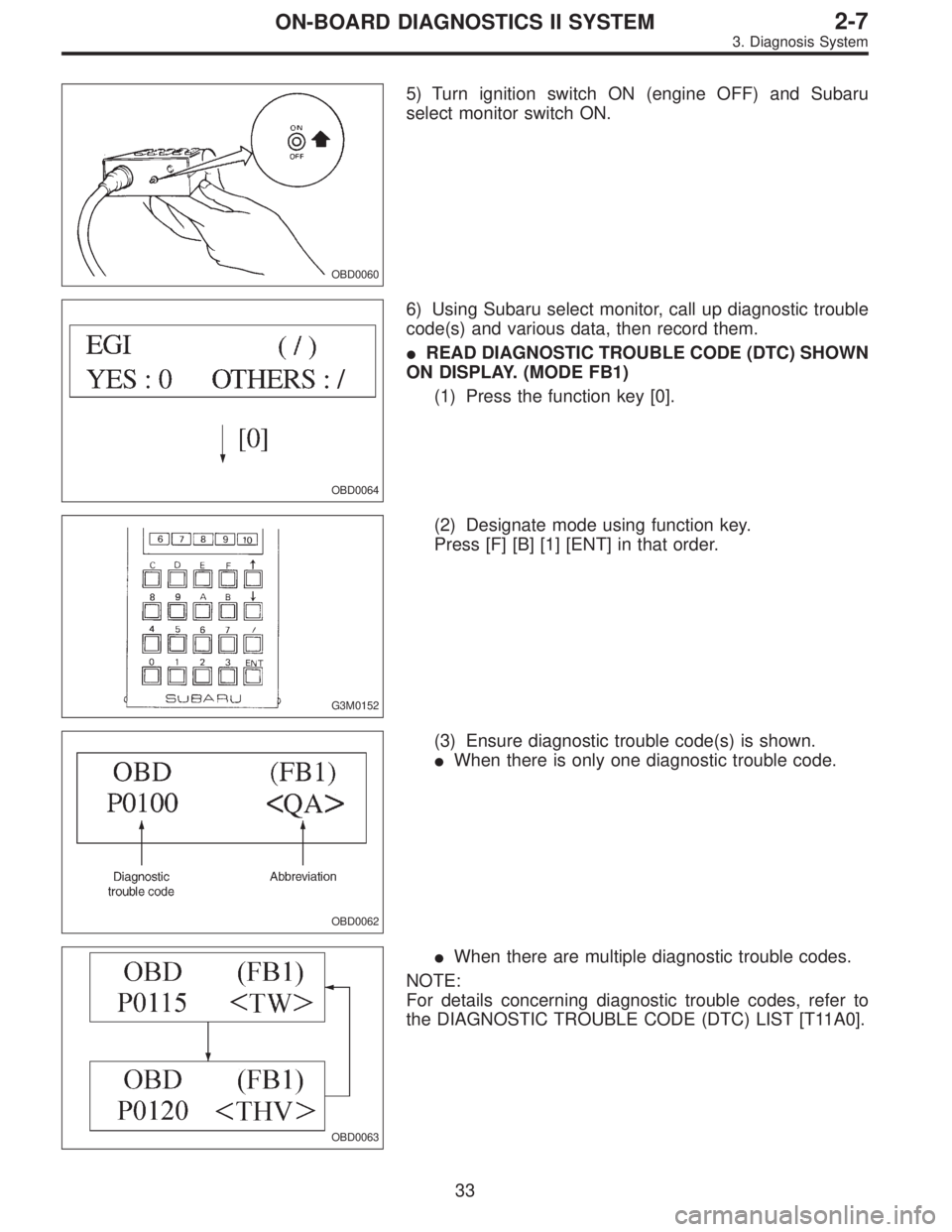
OBD0060
5) Turn ignition switch ON (engine OFF) and Subaru
select monitor switch ON.
OBD0064
6) Using Subaru select monitor, call up diagnostic trouble
code(s) and various data, then record them.
�READ DIAGNOSTIC TROUBLE CODE (DTC) SHOWN
ON DISPLAY. (MODE FB1)
(1) Press the function key [0].
G3M0152
(2) Designate mode using function key.
Press [F] [B] [1] [ENT] in that order.
OBD0062
(3) Ensure diagnostic trouble code(s) is shown.
�When there is only one diagnostic trouble code.
OBD0063
�When there are multiple diagnostic trouble codes.
NOTE:
For details concerning diagnostic trouble codes, refer to
the DIAGNOSTIC TROUBLE CODE (DTC) LIST [T11A0].
33
2-7ON-BOARD DIAGNOSTICS II SYSTEM
3. Diagnosis System