Page 1678 of 2248
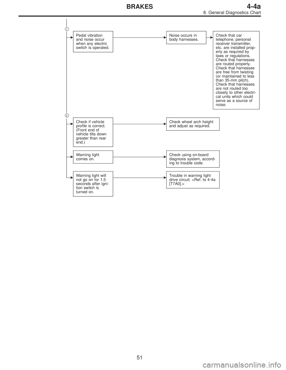
�1
�Pedal vibration
and noise occur
when any electric
switch is operated.�Noise occurs in
body harnesses.�Check that car
telephone, personal
receiver transmitter,
etc. are installed prop-
erly as required by
laws or regulations.
Check that harnesses
are routed properly.
Check that harnesses
are free from twisting
(or maintained to less
than 35-mm pitch).
Check that harnesses
are not routed too
closely to other electri-
cal units which could
serve as a source of
noise.
�2
�Check if vehicle
profile is correct.
(Front end of
vehicle tilts down
greater than rear
end.)�Check wheel arch height
and adjust as required.
�Warning light
comes on.�Check using on-board
diagnosis system, accord-
ing to trouble code.
�Warning light will
not go on for 1.5
seconds after igni-
tion switch is
turned on.�Trouble in warning light
drive circuit.
[T7A0].>
51
4-4aBRAKES
8. General Diagnostics Chart
Page 1679 of 2248
 roads�Stopping distance may sometimes be longer
than for models not equipped with A.B.S.
Check if stopping
d")
B: EXCESSIVE STOPPING DISTANCE
Stopping distance is
too great.�Snowy or sandy (low“µ”) roads�Stopping distance may sometimes be longer
than for models not equipped with A.B.S.
Check if stopping
distance continues
to be excessive
when A.B.S. is inac-
tivated by discon-
necting hydraulic
control unit connec-
tor.
�Ye s�Check wheels and
associated parts for
looseness.
Check tires for
improper specifica-
tions.
Check G sensor for
improper operation.
Bleed air from brake
line.
Check brake system
for abnormalities.
�No�Hydraulic control
unit operation
check.
[W15B0].>�No�Check hydraulic
control unit.
�Ye s�Go to A-�1.
C: IMPROPER PEDAL OPERATION
Pedal does not
operate prop-
erly.
�Long pedal
stroke�
Check if brakes
operate prop-
erly.
�Ye s�On A.B.S. equipped model, pedal stroke may be
slightly longer than for models which are not
equipped with A.B.S.
�No�Bleed air from
brake line.
�Short pedal
stroke�
Check if brakes
operate prop-
erly.
�Ye s�Normal
�No�Check if brakes
operate prop-
erly when
A.B.S. is inacti-
vated by dis-
connecting
hydraulic con-
trol unit connec-
tor.�Ye s�Go to A-�1.
�No�Check brake
system.
�
52
4-4aBRAKES
8. General Diagnostics Chart
Page 1680 of 2248
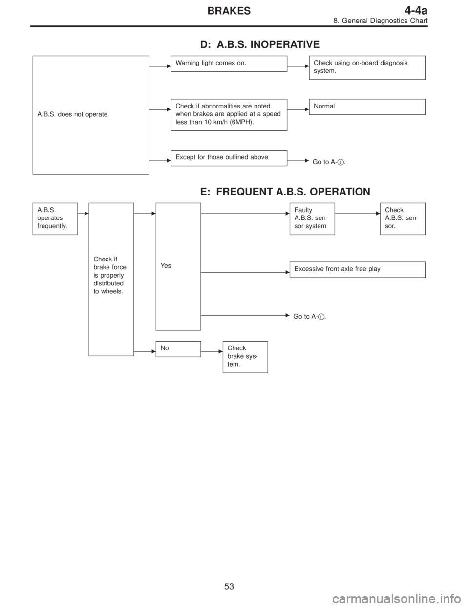
D: A.B.S. INOPERATIVE
A.B.S. does not operate.
�Warning light comes on.�Check using on-board diagnosis
system.
�Check if abnormalities are noted
when brakes are applied at a speed
less than 10 km/h (6MPH).�Normal
�Except for those outlined above�Go to A-�2.
E: FREQUENT A.B.S. OPERATION
A.B.S.
operates
frequently.�
Check if
brake force
is properly
distributed
to wheels.
�
Ye s
�Faulty
A.B.S. sen-
sor system�Check
A.B.S. sen-
sor.
�Excessive front axle free play
�Go to A-�1.
�No�Check
brake sys-
tem.
53
4-4aBRAKES
8. General Diagnostics Chart
Page 1681 of 2248
![SUBARU LEGACY 1995 Service Repair Manual BRAKES
[ABS/TCS]
4-4b
Page
T DIAGNOSTICS
................................................................................2
1. Supplemental Restraint System “Airbag” ...............................](/manual-img/17/57432/w960_57432-1680.png "SUBARU LEGACY 1995 Service Repair Manual BRAKES
[ABS/TCS]
4-4b
Page
T DIAGNOSTICS
................................................................................2
1. Supplemental Restraint System “Airbag” ...............................")
BRAKES
[ABS/TCS]
4-4b
Page
T DIAGNOSTICS
................................................................................2
1. Supplemental Restraint System “Airbag” ................................................2
2. Pre-inspection ..........................................................................................2
3. Electrical Components Location ..............................................................4
4. Schematic ................................................................................................6
5. Control Module I/O Signal .......................................................................7
6. Diagnostics Chart for On-board Diagnosis System...............................13
7. Diagnostics Chart for Warning Light Circuit Failure ..............................18
8. Diagnostics Chart with Trouble Code ....................................................35
9. Select Monitor Function Mode ...............................................................88
10. Diagnostics Chart with Select Monitor...................................................96
11. General Diagnostics Table ...................................................................130
12. Phenomena Peculiar to the System ....................................................131
Page 1684 of 2248
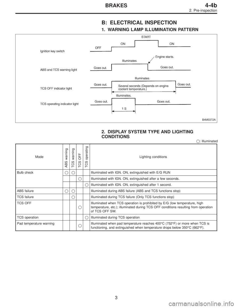
B: ELECTRICAL INSPECTION
1. WARNING LAMP ILLUMINATION PATTERN
B4M0372A
2. DISPLAY SYSTEM TYPE AND LIGHTING
CONDITIONS
�: Illuminated
Mode
ABS warning
TCS warning
TCS OFF
TCS operating
Lighting conditions
Bulb check��Illuminated with IGN. ON, extinguished with E/G RUN
�Illuminated with IGN. ON, extinguished after a few seconds.
�Illuminated with IGN. ON, extinguished after 1 second.
ABS failure��Illuminated during ABS failure (ABS and TCS functions stop)
TCS failure�Illuminated during TCS failure (Only TCS functions stop)
TCS OFF
�Illuminated when TCS operation is prohibited by E/G (low temperature, high
temperature, etc.); illuminated during TCS OFF conditions resulting from operation
of TCS OFF SW.
TCS operation�Illuminated during TCS operation
Pad temperature warning
�Illuminated when pad temperature reaches 400°C (752°F) or more when TCS is
functioning, and extinguished when temperature drops below 350°C (662°F).
3
4-4bBRAKES
2. Pre-inspection
Page 1685 of 2248
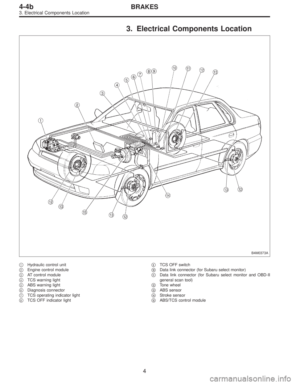
3. Electrical Components Location
B4M0373A
�1Hydraulic control unit
�
2Engine control module
�
3AT control module
�
4TCS warning light
�
5ABS warning light
�
6Diagnosis connector
�
7TCS operating indicator light
�
8TCS OFF indicator light�
9TCS OFF switch
�
10Data link connector (for Subaru select monitor)
�
11Data link connector (for Subaru select monitor and OBD-II
general scan tool)
�
12Tone wheel
�
13ABS sensor
�
14Stroke sensor
�
15ABS/TCS control module
4
4-4bBRAKES
3. Electrical Components Location
Page 1687 of 2248
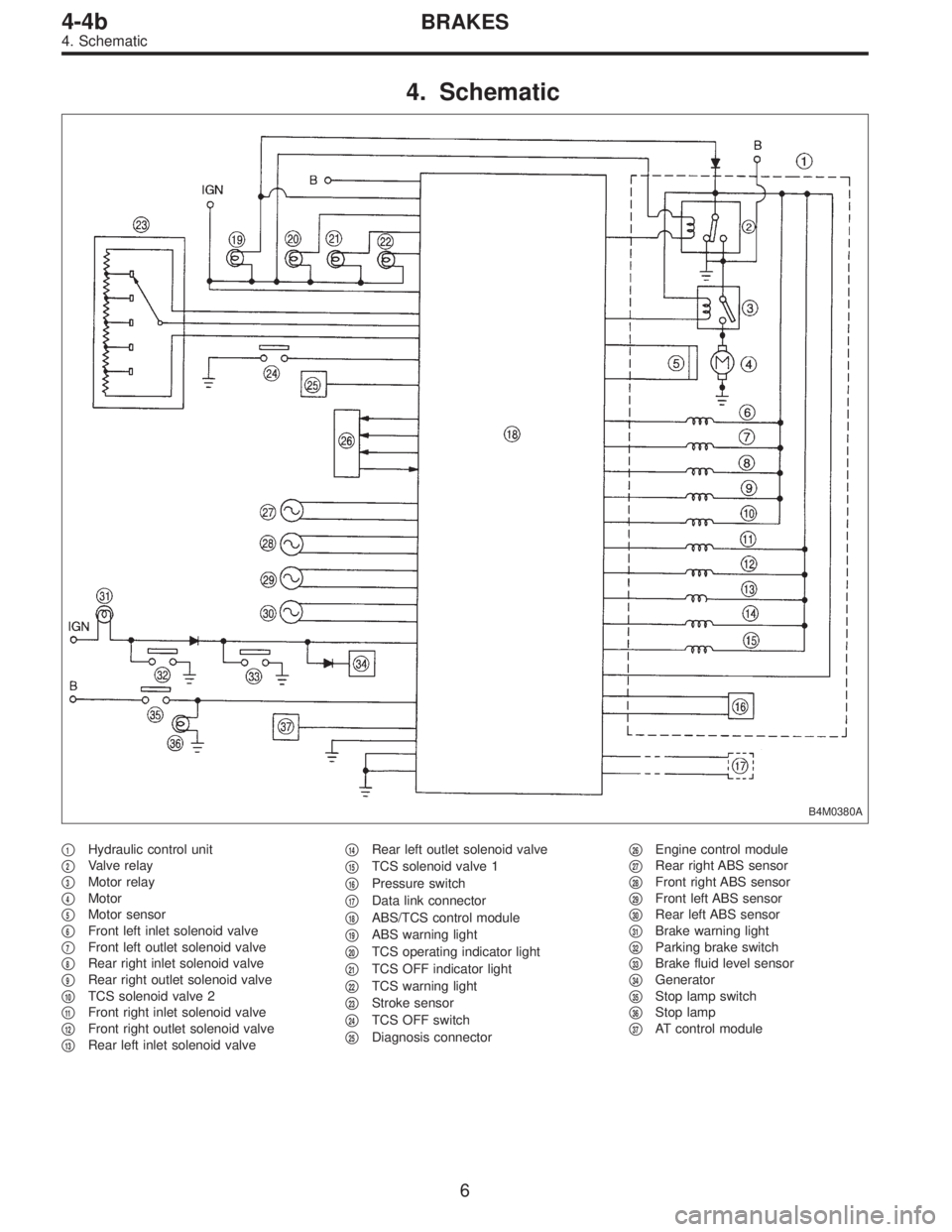
4. Schematic
B4M0380A
�1Hydraulic control unit
�
2Valve relay
�
3Motor relay
�
4Motor
�
5Motor sensor
�
6Front left inlet solenoid valve
�
7Front left outlet solenoid valve
�
8Rear right inlet solenoid valve
�
9Rear right outlet solenoid valve
�
10TCS solenoid valve 2
�
11Front right inlet solenoid valve
�
12Front right outlet solenoid valve
�
13Rear left inlet solenoid valve�
14Rear left outlet solenoid valve
�
15TCS solenoid valve 1
�
16Pressure switch
�
17Data link connector
�
18ABS/TCS control module
�
19ABS warning light
�
20TCS operating indicator light
�
21TCS OFF indicator light
�
22TCS warning light
�
23Stroke sensor
�
24TCS OFF switch
�
25Diagnosis connector�
26Engine control module
�
27Rear right ABS sensor
�
28Front right ABS sensor
�
29Front left ABS sensor
�
30Rear left ABS sensor
�
31Brake warning light
�
32Parking brake switch
�
33Brake fluid level sensor
�
34Generator
�
35Stop lamp switch
�
36Stop lamp
�
37AT control module
6
4-4bBRAKES
4. Schematic
Page 1688 of 2248
Front left wheel P7 1�")
5. Control Module I/O Signal
1. I/O SIGNAL VOLTAGE
Contents Connector No. Terminal No.Input/Output signals
Measured value and measuring conditions
ABS
sensor
(Wheel
speed
sensor)Front left wheel P7 1—11 0.12—1 V (When it is 10 Hz.)
Front right wheel P6 8—16 0.12—1 V (When it is 10 Hz.)
Rear left wheel P6 7—15 0.12—1 V (When it is 10 Hz.)
Rear right wheel P7 2—12 0.12—1 V (When it is 10 Hz.)
Hydraulic
unitSolenoid
valveFront left outlet P4 1—GND
10—14 V when the valve is OFF.
Less than 1.5 V when the valve is ON. Front right outlet P5 3—GND
Rear left outlet P5 8—GND
Rear right outlet P4 3—GND
Front left inlet P4 2—GND
10—14 V when the valve is OFF.
Less than 1.0 V when the valve is ON. Front right inlet P5 2—GND
Rear left inlet P5 7—GND
Rear right inlet P4 4—GND
TCS 1 P4 5—GND
10—14 V when the valve is OFF.
Less than 1.0 V when the valve is ON.
TCS 2 P5 6—GND
Valve power supply P6 6—GND Ignition switch ON, 10—14 V
Valve relay power supply P6 1—GNDLess than 1.2 V when IGN is ON.
10—14 V when the system is down.
Motor relay power supply P6 9—GNDLess than 1.0 V when the motor is ON.
10—14 V when the motor is OFF.
Motor sensor signalsP7 3—GNDCyclic waveform of more than 180 Hz
when the motor across terminals is ON.
Less than 70 Hz when the motor is OFF. P7 13—GND
Pressure switch P7 6—GNDH/L toggle signal with the brake pedal off
(Cycle 14 mS, H: 10—14 V, L: less than
0.7 V). 10—14 V with the brake pedal
depressed.
Pedal
stroke
sensorOutput signals P7 5—GND 0.7—0.9 V with the brake pedal off.
Power supply P7 4—14 5±0.4 V
Stop light
switchSwitch P7 7—GNDLess than 2 V when the stop light is off.
10—12 V when the stop light is on.
Switch test signal P7 18—GNDH/L toggle signal with the brake pedal off
(Cycle 14 mS, H: 10—12 V, L: less than
0.7 V). Less than 2 V with the brake pedal
depressed.
TCS OFF switch P7 16—GNDLess than 2.0 V with the switch pressed
and 10—12 V with it released.
Indicator
lightTCS OFF P6 10—GND
Less than2Vwhenthelight is on and
10—12 V when it is off. TCS operation P6 11—GND
TCS warning P6 3—GND
ABS warning P6 2—GND
7
4-4bBRAKES
5. Control Module I/O Signal