Page 1637 of 2248
![SUBARU LEGACY 1995 Service Repair Manual 7. Diagnostics Chart with Trouble Code
Trouble code Contents of diagnosis Ref. to 4-4a
NONE: A
[Warning light OFF]Trouble in warning light drive circuit
(Warning light is not on for 1.5 seconds after](/manual-img/17/57432/w960_57432-1636.png "SUBARU LEGACY 1995 Service Repair Manual 7. Diagnostics Chart with Trouble Code
Trouble code Contents of diagnosis Ref. to 4-4a
NONE: A
[Warning light OFF]Trouble in warning light drive circuit
(Warning light is not on for 1.5 seconds after")
7. Diagnostics Chart with Trouble Code
Trouble code Contents of diagnosis Ref. to 4-4a
NONE: A
[Warning light OFF]Trouble in warning light drive circuit
(Warning light is not on for 1.5 seconds after ignition switch is on.)[T7A0]
NONE: B
[Warning light ON] or
[Abnormal trouble code output]Trouble in warning light drive circuit [T7B0]
11Start code:
�Trouble code is shown after start code.
�Only start code is shown in normal condition.—
21
Faulty A.B.S. sensor
(Open circuit or input voltage
excessive)Front right wheel sensor [T7C0]
23 Front left wheel sensor [T7C0]
25 Rear right wheel sensor [T7C0]
27 Rear left wheel sensor [T7C0]
22
Faulty A.B.S. sensor
(When there is no open circuit or
speed signal input.)Front right wheel sensor [T7D0]
24 Front left wheel sensor [T7D0]
26 Rear right wheel sensor [T7D0]
28 Rear left wheel sensor [T7D0]
29 Faulty tone wheel, etc. [T7E0]
31
Faulty solenoid valve circuit(s) in
hydraulic control unitFront right wheel control [T7F0]
33 Front left wheel control [T7F0]
39 Rear wheels control [T7F0]
41 Faulty A.B.S. control module [T7G0]
42 Source voltage is low. [T7H0]
51 Faulty valve relay [T7I0]
52 Faulty hydraulic motor and/or motor relay [T7J0]
54 Faulty stop light circuit [T7K0]
56 Use of improper A.B.S. control module specification, or faulty G sensor [T7L0]
NOTE:
After diagnostics is completed, make sure to clear memory.
Make sure only start code (11) is shown after memory is
cleared.
10
4-4aBRAKES
7. Diagnostics Chart with Trouble Code
Page 1638 of 2248
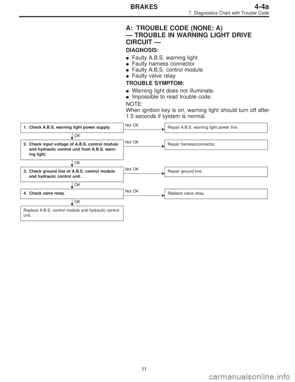
A: TROUBLE CODE (NONE: A)
—TROUBLE IN WARNING LIGHT DRIVE
CIRCUIT—
DIAGNOSIS:
�Faulty A.B.S. warning light
�Faulty harness connector
�Faulty A.B.S. control module
�Faulty valve relay
TROUBLE SYMPTOM:
�Warning light does not illuminate.
�Impossible to read trouble code.
NOTE:
When ignition key is on, warning light should turn off after
1.5 seconds if system is normal.
1. Check A.B.S. warning light power supply.
OK
�Not OK
Repair A.B.S. warning light power line.
2. Check input voltage of A.B.S. control module
and hydraulic control unit from A.B.S. warn-
ing light.
OK
�Not OK
Repair harness/connector.
3. Check ground line of A.B.S. control module
and hydraulic control unit.
OK
�Not OK
Repair ground line.
4. Check valve relay.
OK
�Not OK
Replace valve relay.
Replace A.B.S. control module and hydraulic control
unit.
�
�
�
�
11
4-4aBRAKES
7. Diagnostics Chart with Trouble Code
Page 1639 of 2248
B4M0575
B4M0235B
1. CHECK A.B.S. WARNING LIGHT POWER SUPPLY.
1) Turn ignition switch OFF.
2) Disconnect combination meter.
3) Check A.B.S. warning light valve.
4) Turn ignition switch ON.
5) Measure voltage between combination meter connector
and body.
Connector & terminal / Specified voltage:
(i14) No. 11 — Body / 10 — 12 V
12
4-4aBRAKES
7. Diagnostics Chart with Trouble Code
Page 1640 of 2248
 Turn ignition switch OFF and remove combination
meter.
2) Disconnect connector from A.")
B4M0236B
2. CHECK INPUT VOLTAGE OF A.B.S. CONTROL
MODULE AND HYDRAULIC CONTROL UNIT FROM
A.B.S. WARNING LIGHT.
1) Turn ignition switch OFF and remove combination
meter.
2) Disconnect connector from A.B.S. control module and
hydraulic control unit.
3) Turn ignition switch ON.
4) Measure voltage between A.B.S. control module and
body, and between hydraulic control unit and body.
Connector & terminal / Specified voltage:
(P3) No. 29—body / 10—12 V
(F9) No. 10—body / 10—12 V
B4M0237B
3. CHECK GROUND LINE OF A.B.S. CONTROL
MODULE AND HYDRAULIC CONTROL UNIT.
Measure resistance between A.B.S. control module and
body, and between hydraulic control unit and body.
Connector & terminal / Specified resistance:
(P3) No. 10—body / 0Ω
(P3) No. 20—body / 0Ω
(P3) No. 34—body / 0Ω
(F9) No. 8—body / 0Ω
G4M0690
4. CHECK VALVE RELAY.
1) Remove valve relay.
2) Attach circuit tester probes to terminals, as shown in
figure.
3) Measure resistance between respective terminals.
Terminal / Specified resistance:
No. 87—No. 30 / 0Ω(when 12 volts applied.)
No. 87—No.30/1MΩ(when no volts applied.)
No. 87a—No.30/1MΩ(when 12 volts applied.)
No. 87a—No. 30 / 0Ω(when no volts applied.)
13
4-4aBRAKES
7. Diagnostics Chart with Trouble Code
Page 1641 of 2248
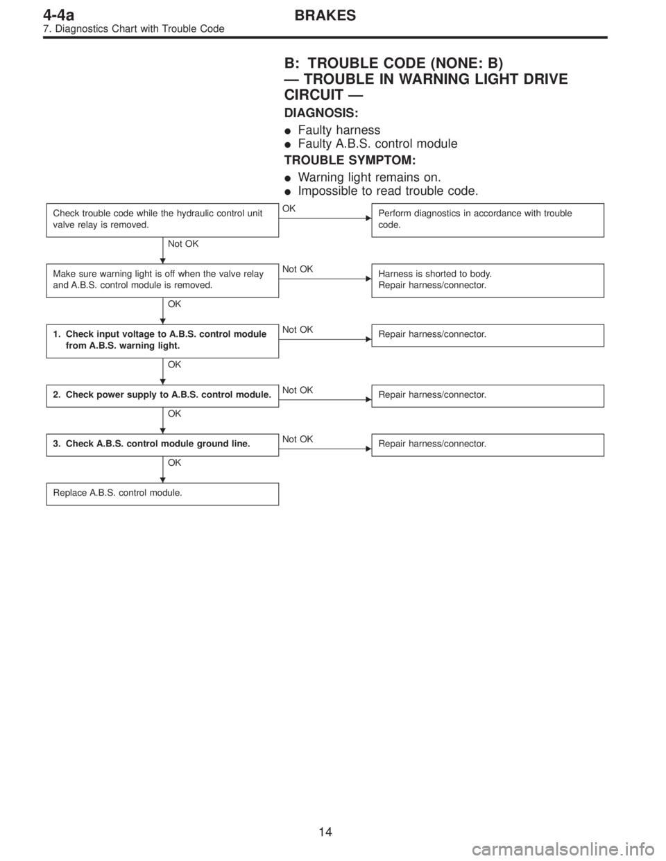
B: TROUBLE CODE (NONE: B)
—TROUBLE IN WARNING LIGHT DRIVE
CIRCUIT—
DIAGNOSIS:
�Faulty harness
�Faulty A.B.S. control module
TROUBLE SYMPTOM:
�Warning light remains on.
�Impossible to read trouble code.
Check trouble code while the hydraulic control unit
valve relay is removed.
Not OK
�OK
Perform diagnostics in accordance with trouble
code.
Make sure warning light is off when the valve relay
and A.B.S. control module is removed.
OK
�Not OK
Harness is shorted to body.
Repair harness/connector.
1. Check input voltage to A.B.S. control module
from A.B.S. warning light.
OK
�Not OK
Repair harness/connector.
2. Check power supply to A.B.S. control module.
OK
�Not OK
Repair harness/connector.
3. Check A.B.S. control module ground line.
OK
�Not OK
Repair harness/connector.
Replace A.B.S. control module.
�
�
�
�
�
14
4-4aBRAKES
7. Diagnostics Chart with Trouble Code
Page 1642 of 2248
B4M0579
B4M0240B
1. CHECK INPUT VOLTAGE TO A.B.S. CONTROL
MODULE FROM A.B.S. WARNING LIGHT.
1) Turn ignition switch OFF.
2) Disconnect connector from A.B.S. control module.
3) Turn ignition switch ON.
4) Measure voltage between A.B.S. control module con-
nector and body.
Connector & terminal / Specified voltage:
(P3) No. 29—Body / 10—12 V
B4M0241B
2. CHECK POWER SUPPLY TO A.B.S. CONTROL
MODULE.
1) Turn ignition switch ON.
2) Measure voltage between A.B.S. control module con-
nector and body.
Connector & terminal / Specified voltage:
(P3) No. 1—Body / 10—12 V
15
4-4aBRAKES
7. Diagnostics Chart with Trouble Code
Page 1672 of 2248
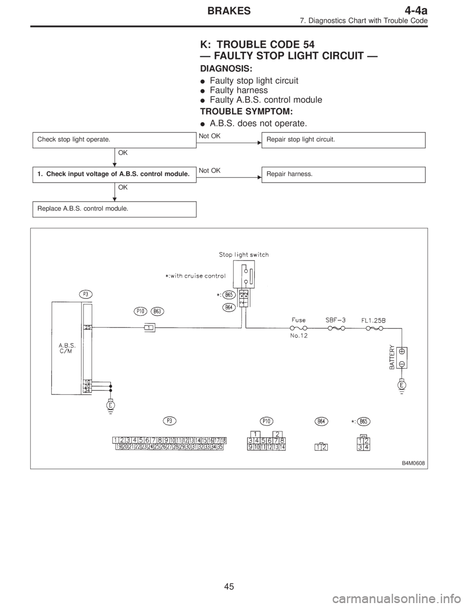
K: TROUBLE CODE 54
—FAULTY STOP LIGHT CIRCUIT—
DIAGNOSIS:
�Faulty stop light circuit
�Faulty harness
�Faulty A.B.S. control module
TROUBLE SYMPTOM:
�A.B.S. does not operate.
Check stop light operate.
OK
�Not OK
Repair stop light circuit.
1. Check input voltage of A.B.S. control module.
OK
�Not OK
Repair harness.
Replace A.B.S. control module.
B4M0608
�
�
45
4-4aBRAKES
7. Diagnostics Chart with Trouble Code
Page 1674 of 2248
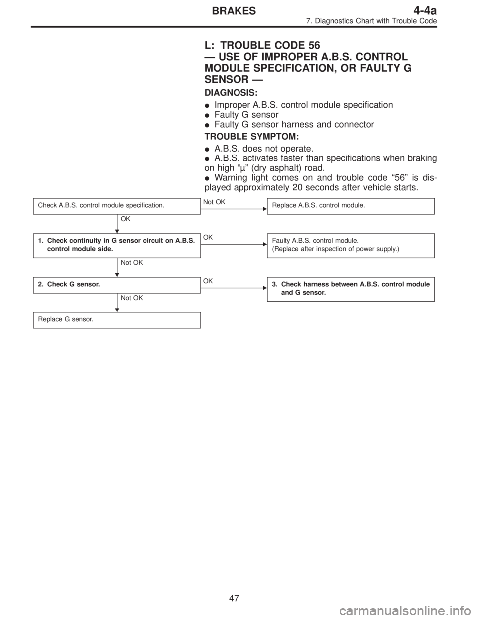
L: TROUBLE CODE 56
—USE OF IMPROPER A.B.S. CONTROL
MODULE SPECIFICATION, OR FAULTY G
SENSOR—
DIAGNOSIS:
�Improper A.B.S. control module specification
�Faulty G sensor
�Faulty G sensor harness and connector
TROUBLE SYMPTOM:
�A.B.S. does not operate.
�A.B.S. activates faster than specifications when braking
on high“µ”(dry asphalt) road.
�Warning light comes on and trouble code“56”is dis-
played approximately 20 seconds after vehicle starts.
Check A.B.S. control module specification.
OK
�Not OK
Replace A.B.S. control module.
1. Check continuity in G sensor circuit on A.B.S.
control module side.
Not OK
�OK
Faulty A.B.S. control module.
(Replace after inspection of power supply.)
2. Check G sensor.
Not OK
�OK
3. Check harness between A.B.S. control module
and G sensor.
Replace G sensor.
�
�
�
47
4-4aBRAKES
7. Diagnostics Chart with Trouble Code
 Turn ignition switch OFF.
2) Disconnect combination meter.
3) Check A.B.S. warning light valve.
4) Turn ignition switch ON.
5) Measure v")
 Turn ignition switch OFF.
2) Disconnect connector from A.B.S. control module.
3) Turn ignition switch ON.")