Page 1499 of 2248
7
CHECK INHIBITOR SWITCH CIRCUIT.
: Is there any trouble in inhibitor switch cir-
cuit?
: Repair or replace inhibitor switch circuit.
: Go to step 8.
8
CHECK BRAKE LIGHT SWITCH CIRCUIT.
: Is there any trouble in brake light switch cir-
cuit?
: Repair or replace brake light switch circuit.
: Go to step 9.
9CHECK ATF TEMPERATURE SENSOR CIR-
CUIT.
: Is there any trouble in ATF temperature sen-
sor circuit?
: Repair or replace ATF temperature sensor circuit.
: Go to next.
: Is there poor contact in TCM connector?
: Repair poor contact in TCM connector.
: Go to next.
: Is there any mechanical trouble in automatic
transmission?
: Repair or replace automatic transmission.
: Replace TCM with a new one.
293
2-7ON-BOARD DIAGNOSTICS II SYSTEM
11. Diagnostics Chart with Trouble Code
Page 1534 of 2248
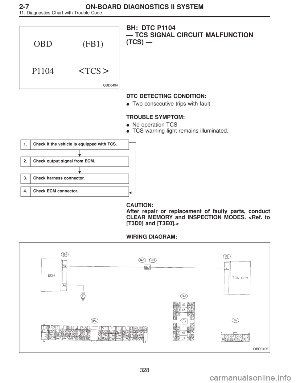
OBD0494
BH: DTC P1104
—TCS SIGNAL CIRCUIT MALFUNCTION
(TCS)—
DTC DETECTING CONDITION:
�Two consecutive trips with fault
TROUBLE SYMPTOM:
�No operation TCS
�TCS warning light remains illuminated.
1.Check if the vehicle is equipped with TCS.
�
2.Check output signal from ECM.
3.Check harness connector.
4.Check ECM connector.
CAUTION:
After repair or replacement of faulty parts, conduct
CLEAR MEMORY and INSPECTION MODES.
[T3D0] and [T3E0].>
WIRING DIAGRAM:
OBD0495
�
�
328
2-7ON-BOARD DIAGNOSTICS II SYSTEM
11. Diagnostics Chart with Trouble Code
Page 1557 of 2248
 Check that selector lever does not move from“N”to“R”
without pushing the bu")
G3M0717
3. OPERATION OF SHIFT SELECTOR LEVER
WARNING:
Stop the engine while checking operation of selector
lever.
1) Check that selector lever does not move from“N”to“R”
without pushing the button.
2) Check that selector lever does not move from“R”to“P”
without pushing the button.
3) Check that selector lever does not move from“P”to“R”
without pushing the button.
4) Check that selector lever does not move from“3”to“2”
without pushing the button.
3. Electrical Components Location
1. SENSOR AND CONTROL MODULE
B3M0178B
�1Throttle position sensor
�
2Dropping resistor
�
3Vehicle speed sensor 2
�
4Inhibitor switch
�
5ECM
�
6Vehicle speed sensor 1 (AWD)
�
7Vehicle speed sensor 1 (FWD)
�
8TCM�
9Data link connector (for Subaru select monitor only)
�
10Data link connector (for Subaru select monitor and OBD-II
general scan tool)
�
11Diagnosis connector
�
12Diagnosis terminal
�
13AT OIL TEMP indicator light
(AT diagnostic indicator light)
3
3-2AUTOMATIC TRANSMISSION AND DIFFERENTIAL
2. Pre-inspection - 3. Electrical Components Location
Page 1558 of 2248
 Check that selector lever does not move from“N”to“R”
without pushing the bu")
G3M0717
3. OPERATION OF SHIFT SELECTOR LEVER
WARNING:
Stop the engine while checking operation of selector
lever.
1) Check that selector lever does not move from“N”to“R”
without pushing the button.
2) Check that selector lever does not move from“R”to“P”
without pushing the button.
3) Check that selector lever does not move from“P”to“R”
without pushing the button.
4) Check that selector lever does not move from“3”to“2”
without pushing the button.
3. Electrical Components Location
1. SENSOR AND CONTROL MODULE
B3M0178B
�1Throttle position sensor
�
2Dropping resistor
�
3Vehicle speed sensor 2
�
4Inhibitor switch
�
5ECM
�
6Vehicle speed sensor 1 (AWD)
�
7Vehicle speed sensor 1 (FWD)
�
8TCM�
9Data link connector (for Subaru select monitor only)
�
10Data link connector (for Subaru select monitor and OBD-II
general scan tool)
�
11Diagnosis connector
�
12Diagnosis terminal
�
13AT OIL TEMP indicator light
(AT diagnostic indicator light)
3
3-2AUTOMATIC TRANSMISSION AND DIFFERENTIAL
2. Pre-inspection - 3. Electrical Components Location
Page 1569 of 2248
 indicates a“ten”, and the
short se")
2. HOW TO READ TROUBLE CODE OF INDICATOR
LIGHT
The AT OIL TEMP indicator light flashes the code corre-
sponding to the faulty part.
The long segment (1.2 sec on) indicates a“ten”, and the
short segment (0.2 sec on) signifies a“one”.
B3M0193A
E: CLEAR MEMORY
Current trouble codes shown on the display are cleared by
turning the ignition switch OFF after conducting on-board
diagnostic operation. Previous trouble codes, however,
cannot be cleared since they are stored in the TCM
memory which is operating on the back-up power supply.
These trouble codes can be cleared by removing the speci-
fied fuse (located under the right lower portion of the instru-
ment panel).
CLEAR MEMORY:
Removal of No. 14 fuse (for at least one minute)
�The No. 14 fuse is located in the line to the memory
back-up power supply of the TCM and ABS/TCS control
module. Removal of this fuse clears the previous trouble
codes stored in the TCM and ABS/TCS control module
memory.
�Be sure to remove the No. 14 fuse for at least the speci-
fied length of time. Otherwise, trouble codes may not be
cleared.
14
3-2AUTOMATIC TRANSMISSION AND DIFFERENTIAL
6. Diagnostic Chart for On-board Diagnostic System
Page 1576 of 2248
 Connect connectors to TCM and transmission.
2) Lift-up the vehicle or set the vehicle on free roller.
CAUTION:
On AWD models, raise all wheels off")
OBD0607A
4. CHECK OUTPUT SIGNAL EMITTED FROM TCM.
1) Connect connectors to TCM and transmission.
2) Lift-up the vehicle or set the vehicle on free roller.
CAUTION:
On AWD models, raise all wheels off floor.
3) Start and warm-up the engine and transmission.
4) Push the TCS OFF switch to ON. (With TCS models)
5) Move selector lever to“D”and slowly increase vehicle
speed to 75 km/h (47 MPH).
6) Measure voltage between TCM connector terminals.
Connector & terminal / Specified voltage:
(B55) No. 5—No. 10 / 8.5 V, or more (when
wheels are locked-up.)
OBD0607A
7) Return the engine to idling speed and move selector
lever to“N”.
8) Measure voltage between TCM connector terminals.
Connector & terminal / Specified voltage:
(B55) No. 5—No. 10 / 0.5 V, or less
NOTE:
The speed difference between front and rear wheels may
light either the ABS or the ABS/TCS warning light, but this
indicates no malfunctions. When AT control diagnosis is
finished, perform the ABS or the ABS/TCS memory clear-
ance procedure of self-diagnosis system.
OBD0145A
�Using Subaru select monitor:
(1) Connect connectors to TCM and transmission.
(2) Lift-up the vehicle or set the vehicle on free roller.
CAUTION:
On AWD models, raise all wheels off floor.
(3) Turn ignition switch to OFF.
(4) Connect the Subaru select monitor to data link con-
nector.
(5) Turn ignition switch to ON and Subaru select moni-
tor switch to ON.
21
3-2AUTOMATIC TRANSMISSION AND DIFFERENTIAL
7. Diagnostic Chart with Trouble Code
Page 1577 of 2248
OBD0417
(6) Start and warm-up the engine and transmission.
(7) Push the TCS OFF switch to ON. (With TCS mod-
els)
(8) Designate mode using function key.
Function mode: F12
(9) Move selector lever to“D”and slowly increase
vehicle speed to 75 km/h (47 MPH).
(10) Read data on Subaru select monitor.
SPECIFIED DATA:
�95% (Wheel locked-up)
�5% (Released)
NOTE:
The speed difference between front and rear wheels may
light either the ABS or the ABS/TCS warning light, but this
indicates no malfunctions. When AT control diagnosis is
finished, perform the ABS or the ABS/TCS memory clear-
ance procedure of self-diagnosis system.
22
3-2AUTOMATIC TRANSMISSION AND DIFFERENTIAL
7. Diagnostic Chart with Trouble Code
Page 1579 of 2248
 Measure resistance of harness connector between
TCM and body to make sure that circuit does not short.
Connector & terminal / Specified resistance:
(B55) No. 15—Body/1MΩ, or more
(B55)")
OBD0455A
4) Measure resistance of harness connector between
TCM and body to make sure that circuit does not short.
Connector & terminal / Specified resistance:
(B55) No. 15—Body/1MΩ, or more
(B55) No. 10—Body/1MΩ, or more
G3M0109
2. CHECK SHIFT SOLENOID 3’s GROUND LINE.
Measure resistance between transmission connector
receptacle and transmission case.
Connector & terminal / Specified resistance:
(T4) No. 4—Transmission / 1Ω, or less
G3M0117
3. CHECK SHIFT SOLENOID 3.
Measure resistance between transmission connector
receptacle’s terminals.
Connector & terminal / Specified resistance:
(T4) No. 1—No.4/20—32Ω
B3M0381A
4. CHECK OUTPUT SIGNAL EMITTED FROM TCM.
1) Connect connectors to TCM and transmission.
2) Lift-up or raise the vehicle and support with safety
stands.
CAUTION:
On AWD models, raise all wheels off ground.
3) Start and warm-up the engine and transmission.
4) Idle the engine.
5) Move selector lever to“D”.
6) Measure voltage between TCM connector terminals.
Connector & terminal / Specified voltage:
(B55) No. 15—No. 10 / 9 V, or more
NOTE:
The speed difference between front and rear wheels may
light either the ABS or the ABS/TCS warning light, but this
indicates no malfunctions. When AT control diagnosis is
finished, perform the ABS or the ABS/TCS memory clear-
ance procedure of self-diagnosis system.
24
3-2AUTOMATIC TRANSMISSION AND DIFFERENTIAL
7. Diagnostic Chart with Trouble Code

 Start and warm-up the engine and transmission.
(7) Push the TCS OFF switch to ON. (With TCS mod-
els)
(8) Designate mode using function key.
Function mode: F12
(9) Move selector lever to�")