Page 1228 of 2248
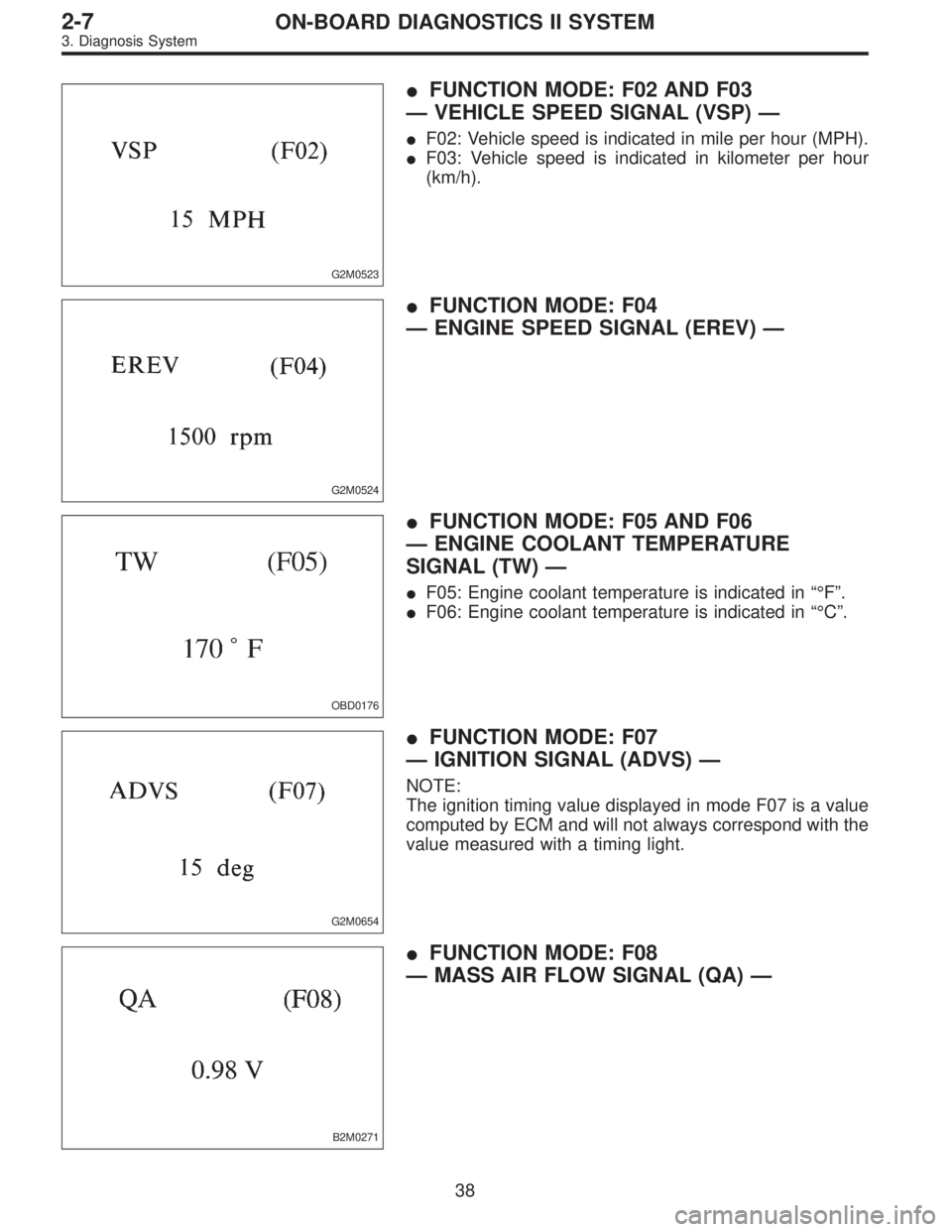
2. MODULE (RHD MODEL)
B2M0430C
�1Transmission Control Module (TCM)�2AT diagnostic indicator light
B2M0436AOBD0008B
22
2-7ON-BOARD DIAGNOSTICS II SYSTEM
2. Electrical Components Location
Page 1229 of 2248
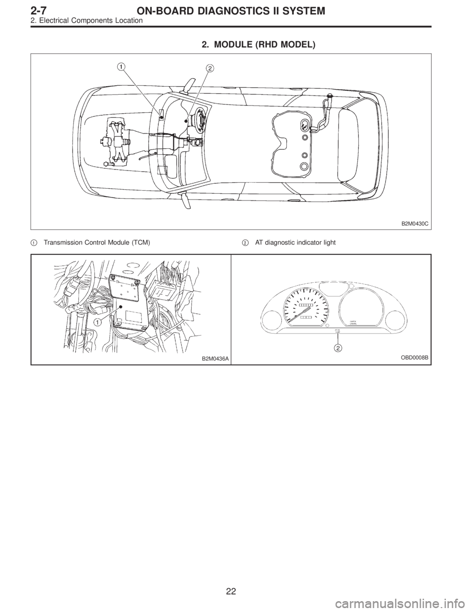
3. SENSOR (LHD MODEL)
OBD0041AOBD0042A
OBD0043AOBD0044A
H2M1145COBD0653A
�1Vehicle speed sensor 1 (for AT FWD vehicles)
�
2Vehicle speed sensor 1 (for AT AWD vehicles)
�
3Vehicle speed sensor 2 (for MT vehicles)�
4Vehicle speed sensor 2 (for AT vehicles)
�
5ATF temperature sensor (for AT vehicles)
�
6Brake light switch
23
2-7ON-BOARD DIAGNOSTICS II SYSTEM
2. Electrical Components Location
Page 1230 of 2248
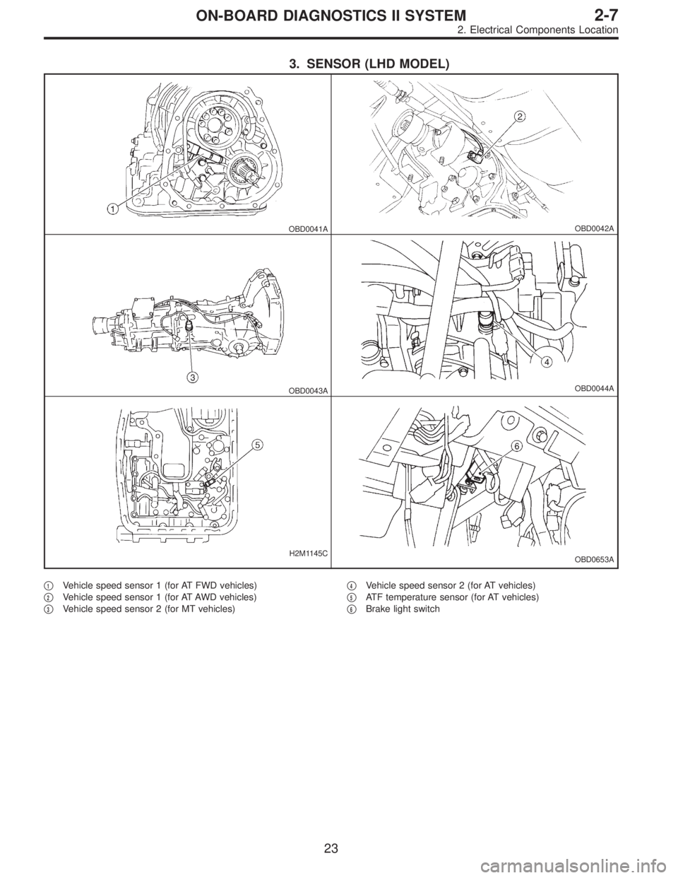
4. SENSOR (RHD MODEL)
OBD0042BOBD0044B
B2M0464AB2M0437A
�1Vehicle speed sensor 1
�
2Vehicle speed sensor 2�
3ATF temperature sensor
�
4Brake light switch
24
2-7ON-BOARD DIAGNOSTICS II SYSTEM
2. Electrical Components Location
Page 1233 of 2248
OBD0008C
3. Diagnosis System
A: MALFUNCTION INDICATOR LAMP (MIL)
1. ACTIVATION OF MALFUNCTION INDICATOR LAMP
(MIL)
1) When ignition switch is turned to ON (engine off), the
CHECK ENGINE malfunction indicator lamp (MIL) in the
combination meter illuminates.
NOTE:
If the MIL does not illuminate, perform diagnostics of the
CHECK ENGINE light circuit or the combination meter cir-
cuit.
function Indicator Lamp (MIL) [T800]”.>
OBD0053A
2) After starting the engine, the MIL goes out. If it does not,
either the engine or the emission control system is mal-
functioning.
OBD0054A
3) If the diagnosis system senses a misfire which could
damage the catalyzer, the MIL will blink at a cycle of 1 Hz.
OBD0055A
4) When ignition switch is turned to ON (engine off) or to
“START” with the test mode connector connected, the MIL
blinks at a cycle of 3 Hz.
27
2-7ON-BOARD DIAGNOSTICS II SYSTEM
3. Diagnosis System
Page 1244 of 2248
G2M0523
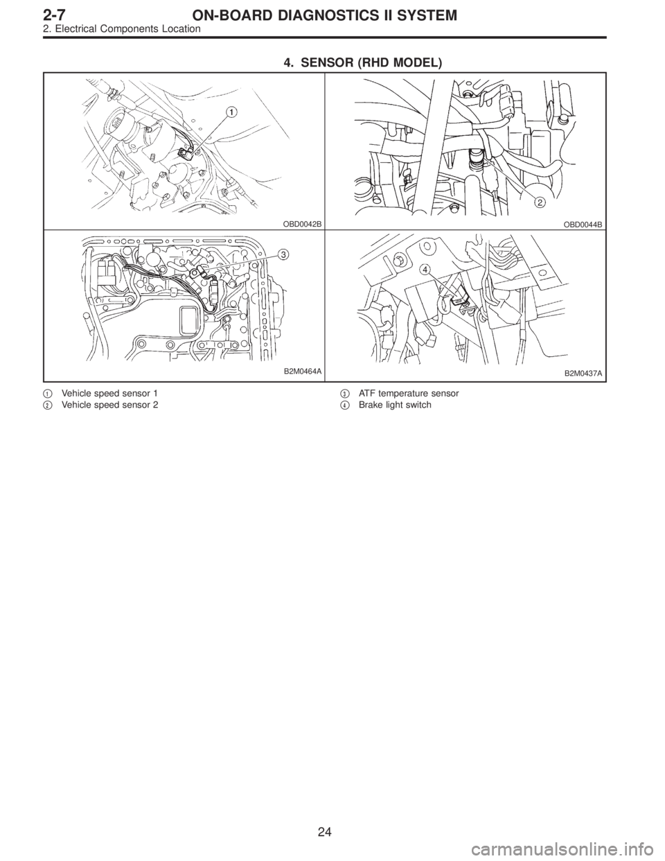
�FUNCTION MODE: F02 AND F03
—VEHICLE SPEED SIGNAL (VSP)—
�F02: Vehicle speed is indicated in mile per hour (MPH).
�F03: Vehicle speed is indicated in kilometer per hour
(km/h).
G2M0524
�FUNCTION MODE: F04
—ENGINE SPEED SIGNAL (EREV)—
OBD0176
�FUNCTION MODE: F05 AND F06
—ENGINE COOLANT TEMPERATURE
SIGNAL (TW)—
�F05: Engine coolant temperature is indicated in“°F”.
�F06: Engine coolant temperature is indicated in“°C”.
G2M0654
�FUNCTION MODE: F07
—IGNITION SIGNAL (ADVS)—
NOTE:
The ignition timing value displayed in mode F07 is a value
computed by ECM and will not always correspond with the
value measured with a timing light.
B2M0271
�FUNCTION MODE: F08
—MASS AIR FLOW SIGNAL (QA)—
38
2-7ON-BOARD DIAGNOSTICS II SYSTEM
3. Diagnosis System
Page 1267 of 2248
 Connect ST to Subaru select monitor cable.
ST 498357200 ADAPTER CABLE
OBD0006C
(2) Open the cover and co")
OBD0669A
�Using data link connector for Subaru select monitor and
OBD-II general scan tool:
(1) Connect ST to Subaru select monitor cable.
ST 498357200 ADAPTER CABLE
OBD0006C
(2) Open the cover and connect Subaru select monitor
to data link connector located in the lower portion of the
instrument panel (on the driver’s side), to the lower
cover.
CAUTION:
Do not connect scan tools except for Subaru select
monitor and OBD-II general scan tool.
OBD0060
6) Turn ignition switch ON (engine OFF) and Subaru
select monitor switch ON.
7) Start the engine.
NOTE:
�Ensure the selector lever is placed in the“P”position
before starting. (AT vehicles)
�Depress clutch pedal when starting the engine. (MT
vehicles)
8) Using the selector lever or shift lever, turn the“P”posi-
tion switch and the“N”position switch to ON.
9) Depress the brake pedal to turn the brake switch ON.
(AT vehicles)
10) Keep engine speed in the 2,500—3,000 rpm range
for 40 seconds.
NOTE:
On models without tachometer, use the Subaru select
monitor or tachometer (Secondary pickup type).
11) Place the selector lever or shift lever in the“D”posi-
tion (AT vehicles) or“1st”gear (MT vehicles) and drive the
vehicle at 5 to 10 km/h (3 to 6 MPH).
NOTE:
�On AWD vehicles, release the parking brake.
�The speed difference between front and rear wheels
may light either the ABS or the ABS/TCS warning light, but
this indicates no malfunctions. When engine control diag-
nosis is finished, perform the ABS or the ABS/TCS memory
clearance procedure of self-diagnosis system.
4-4a [T6C2] or 4-4b [T6C2] or [T9K0].>
61
2-7ON-BOARD DIAGNOSTICS II SYSTEM
3. Diagnosis System
Page 1268 of 2248
 Connect test mode connector at the lower side of the
inst")
OBD0005B
3. OBD-II GENERAL SCAN TOOL
After performing diagnostics and clearing the memory,
check for any remaining unresolved trouble data:
1) Connect test mode connector at the lower side of the
instrument panel (on the driver’s side), to the side of the
center console box.
OBD0006C
2) Open the cover and connect the OBD-II general scan
tool to its data link connector in the lower portion of the
instrument panel (on the driver’s side), to the lower cover.
CAUTION:
Do not connect the scan tools except for Subaru select
monitor and OBD-II general scan tool.
3) Start the engine.
NOTE:
�Ensure the selector lever is placed in the“P”position
before starting. (AT vehicles)
�Depress clutch pedal when starting the engine. (MT
vehicles)
4) Using the selector lever or shift lever, turn the“P”posi-
tion switch and the“N”position switch to ON.
5) Depress the brake pedal to turn the brake switch ON.
(AT vehicles)
6) Keep engine speed in the 2,500—3,000 rpm range for
40 seconds.
NOTE:
On models without tachometer, use the Subaru select
monitor or tachometer (Secondary pickup type).
7) Place the selector lever or shift lever in the“D”position
(AT vehicles) or“1st”gear (MT vehicles) and drive the
vehicle at 5 to 10 km/h (3 to 6 MPH).
NOTE:
�On AWD vehicles, release the parking brake.
�The speed difference between front and rear wheels
may light either the ABS or the ABS/TCS warning light, but
this indicates no malfunctions. When engine control diag-
nosis is finished, perform the ABS or the ABS/TCS memory
clearance procedure of self-diagnosis system.
4-4a [T6C2] or 4-4b [T6C2] or [T9K0].>
62
2-7ON-BOARD DIAGNOSTICS II SYSTEM
3. Diagnosis System
Page 1272 of 2248
 Before disconnecting t")
�When mounting a large power type radio, pay spe-
cial attention to the three items above mentioned.
�Incorrect installation of the radio may affect the
operation of the ECM.
8) Before disconnecting the fuel hose, disconnect the fuel
pump connector and crank the engine for more than five
seconds to release pressure in the fuel system. If engine
starts during this operation, run it until it stops.
9) Problems in the electronic-controlled automatic trans-
mission may be caused by failure of the engine, the elec-
tronic control system, the transmission proper, or by a com-
bination of these. These three causes must be distin-
guished clearly when performing diagnostics.
10) Diagnostics should be conducted by rotating with
simple, easy operations and proceeding to complicated,
difficult operations. The most important thing in diagnostics
is to understand the customer’s complaint, and distinguish
between the three causes.
11) In AT vehicles, do not continue the stall for more than
five seconds at a time (from closed throttle, fully open
throttle to stall engine speed).
12) On ABS or ABS/TCS vehicle, when performing driving
test in jacked-up or lifted-up position, sometimes the warn-
ing light may be lit, but this is not a malfunction of the sys-
tem. The reason for this is the speed difference between
the front and rear wheels. After diagnosis of engine control
system, perform the ABS or ABS/TCS memory clearance
procedure of self-diagnosis system.
4-4b [T6C2] or [T9K0].>
C: PRE-INSPECTION
Before performing diagnostics, check the following items
which might affect engine problems:
1. POWER SUPPLY
1) Measure battery voltage and specific gravity of electro-
lyte.
Standard voltage: 12 V
Specific gravity: Above 1.260
2) Check the condition of the main and other fuses, and
harnesses and connectors. Also check for proper ground-
ing.
OBD0091A
2. ENGINE GROUNDING
Make sure the engine grounding terminal is properly con-
nected to the engine.
66
2-7ON-BOARD DIAGNOSTICS II SYSTEM
4. Cautions

1. ACTIVATION OF MALFUNCTION INDICATOR LAMP
(MIL)
1) When ignition switch is turned to ON (engine off), the
CHECK ENGINE malfunction in")