Page 1191 of 2248

From the previous step
Starter motor runs.
OK
� Not OK
Check starter interrupt relay.
Check wiring harness.
Check security control module.
Check driver’s door unlock switch.
Lock the driver’s door without using a ignition key. (Set the inside
lock knob to LOCK and then close the door while lifting the outer
handle).
Within 30 seconds after the above step, open rear LH door.
Indicator light flashes with short intervals (1 Hz).
OK
� Not OK
Check rear LH door switch.
Check rear LH door switch harness.
Check security control module.
Close and lock door.
Indicator light illuminates continuously.
OK
Perform the above steps also on the rear RH door and front RH
door.
OK
� Not OK
Check rear and front RH door switches.
Check wiring harnesses.
Check security control module.
Pull engine hood opener lever and open engine hood.
Indicator light flashes at short intervals (1 Hz).
OK
� Not OK
Check hood switch.
Check hood switch harness.
Check security control module.
Close engine hood.
Indicator light illuminates continuously.
SEDAN
� WAGON
Unlock rear gate by operating driver’s door inside lock knob and
open rear gate.
Pull trunk opener lever and open trunk lid.Indicator light flashes at short intervals (1 Hz).
OK Not OK
Indicator light flashes at short intervals (1 Hz).
OK Not OKCheck rear gate switch.
Check rear gate switch harness.
Check security control module.
Check trunk switch.
Check trunk switch harness.
Check security control module.Close rear gate and lock by locking driver’s door using a
ignition key.
Close trunk lid.Indicator light illuminates continuously.
Indicator light illuminates continuously.Wait for 30 seconds.
Wait for 30 seconds.Indicator light flashes at long intervals (0.2 sec. ON and 2.4
sec. OFF).
Continues to next step. Continues to next step.
�
�
�
�
�
�
�
�
�
�
�
��
��
��
��
��
��
��
87
6-2DIAGNOSTICS
6. Security System
Page 1192 of 2248
.
Unlock rear gate using a ignition key and open.
Unlock trunk lid using a ignit")
From the previous step. From the previous step.
Indicator light flashes at long intervals (0.2 sec. ON and 2.4 sec.
OFF).
Unlock rear gate using a ignition key and open.
Unlock trunk lid using a ignition key and open.
The alarm system does not operate.
OK Not OKThe alarm system does not operate.OK Not OK
Check trunk unlock switch.
Check trunk unlock switch harness.
Check security control module.
Check rear gate unlock switch.
Check rear gate unlock switch harness.
Check security control module.
Close trunk lid.Close rear gate.
Lock rear gate using a ignition key.
Indicator light illuminates continuously.Indicator light illuminates continuously.
OK Not OK
Check rear gate lock switch.
Check rear gate lock switch harness.
Check security control module.
Wait for 30 seconds.
Indicator light flashes at long intervals (0.2 sec. ON and 2.4 sec.
OFF).
Unlock front RH door using a ignition key and open.
The alarm system does not operate.
OK
� Not OK
Check front RH door key cylinder unlock switch.
Check front RH door key cylinder unlock switch harness.
Check security control module.
Close front RH door and lock using a ignition key.
Indicator light illuminates continuously.
OK
� Not OK
Check front RH door key cylinder lock switch.
Check front RH door key cylinder lock switch harness.
Check security control module.
Finish checking security system.
�
��
�
��
��
��
�
��
�
�
�
�
�
�
�
�
88
6-2DIAGNOSTICS
6. Security System
Page 1195 of 2248

F: DIAGNOSTICS PROCEDURE FOR
SECURITY INDICATOR LIGHT AND
INDICATOR LIGHT CIRCUIT
1. Check security indicator light.
OK
�Not OK
Replace indicator light.
2. Check power supply for indicator light.
OK
�Not OK
Repair or replace wiring harness.
3. Check harness connector between security
indicator light and security control module.
OK
�Not OK
Repair or replace wiring harness.
Go to next step on basic diagnostics procedure.
B6M0382A
1. CHECK SECURITY INDICATOR LIGHT.
1) Remove security indicator light.
2) Measure resistance between security indicator light
connector terminals.
Terminals / Specified resistance:
No. 2—No. 4 / Approx. 120Ω
B6M0443A
2. CHECK POWER SUPPLY FOR INDICATOR LIGHT.
1) Disconnect connector of security indicator light.
2) Measure voltage between security indicator light con-
nector and body.
Connector & terminal / Specified voltage:
(i8) No. 2—Body / 10 V, or more
B6M0498A
3. CHECK HARNESS CONNECTOR BETWEEN
SECURITY INDICATOR LIGHT AND SECURITY
CONTROL MODULE.
1) Disconnect connectors of security indicator light and
security control module.
2) Measure resistance of harness connector between
security indicator light and security control module.
Connector & terminal / Specified resistance:
(i8) No. 4—(B93) No.7/10Ω, max.
�
�
�
91
6-2DIAGNOSTICS
6. Security System
Page 1196 of 2248
G: DIAGNOSTICS PROCEDURE FOR DOOR
SWITCH SIGNAL
1. Check door switch input signal for security
control module.
Not OK
�OK
Go to next step on basic diagnostics procedure.
2. Check door switch.
OK
�Not OK
Replace door switch.
Repair or replace wiring harness between door
switch and security control module.
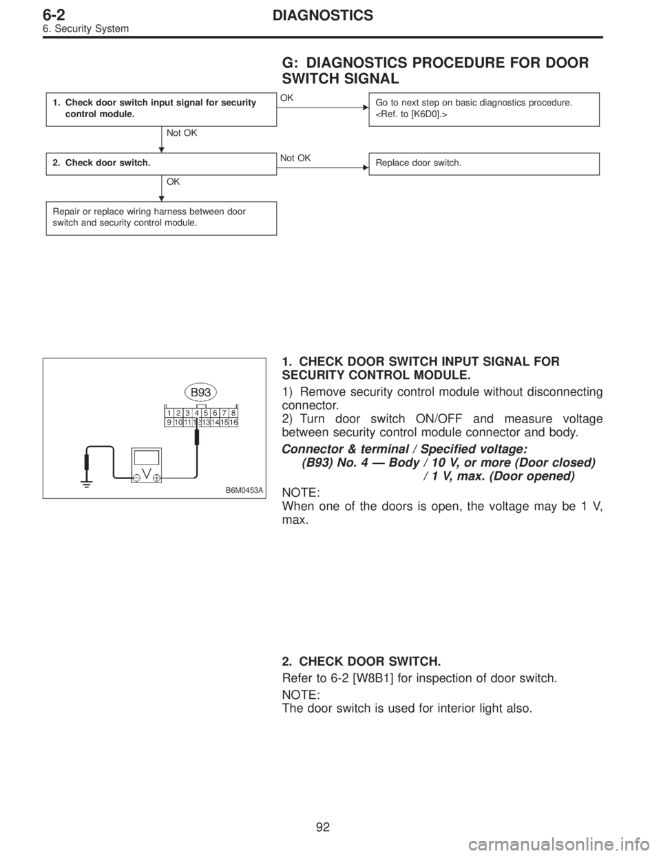
B6M0453A
1. CHECK DOOR SWITCH INPUT SIGNAL FOR
SECURITY CONTROL MODULE.
1) Remove security control module without disconnecting
connector.
2) Turn door switch ON/OFF and measure voltage
between security control module connector and body.
Connector & terminal / Specified voltage:
(B93) No. 4—Body / 10 V, or more (Door closed)
/ 1 V, max. (Door opened)
NOTE:
When one of the doors is open, the voltage may be 1 V,
max.
2. CHECK DOOR SWITCH.
Refer to 6-2 [W8B1] for inspection of door switch.
NOTE:
The door switch is used for interior light also.
�
�
92
6-2DIAGNOSTICS
6. Security System
Page 1198 of 2248
 OR REAR GATE
SWITCH (WAGON) SIGNAL
1. Check trunk lid switch (SEDAN) or rear gate
switch (WAGON) input signal for security
control module.
Not OK")
I: DIAGNOSTICS PROCEDURE FOR TRUNK
LID SWITCH (SEDAN) OR REAR GATE
SWITCH (WAGON) SIGNAL
1. Check trunk lid switch (SEDAN) or rear gate
switch (WAGON) input signal for security
control module.
Not OK
�OK
Go to next step on basic diagnostics procedure.
2. Check trunk lid switch (SEDAN) or rear gate
switch (WAGON).
OK
�Not OK
Replace trunk lid switch (or rear gate switch).
Repair or replace wiring harness between trunk lid
switch (or rear gate switch) and security control
module.
B6M0450A
1. CHECK TRUNK LID SWITCH (SEDAN) OR REAR
GATE SWITCH (WAGON) INPUT SIGNAL FOR
SECURITY CONTROL MODULE.
1) Remove security control module without disconnecting
connector.
2) Turn trunk lid switch (or rear gate switch) ON/OFF and
measure voltage between security control module connec-
tor and body.
Connector & terminal / Specified voltage:
(B93) No. 11—Body / 10 V, or more
(Lid or gate closed)
/ 1 V, max.
(Lid or gate opened)
2. CHECK TRUNK LID SWITCH (SEDAN) OR REAR
GATE SWITCH (WAGON).
Refer to 6-2 [W8B2/W8B3] for inspection of trunk lid switch/
rear gate switch.
NOTE:
The trunk lid switch/rear gate switch is used for both trunk
room light/luggage room light.
�
�
94
6-2DIAGNOSTICS
6. Security System
Page 1206 of 2248

N: DIAGNOSTICS PROCEDURE FOR
HEADLIGHT ALARM SIGNAL
1. Check headlight alarm output signal for security
control module.
Not OK
�OK
5. Check headlight alarm relay.
OK Not OK
Repair or replace
wiring harness of
headlight circuit.
Replace headlight
alarm relay.
2. Check power supply for headlight alarm relay.
OK
�Not OK
Repair or replace wiring harness between
headlight alarm relay and battery.
3. Check continuity of headlight alarm relay.
OK
�Not OK
Replace headlight alarm relay.
4. Check harness connector between headlight
alarm relay and security control module.
OK
�Not OK
Repair or replace wiring harness between
headlight alarm relay and security control
module.
Replace security control module.
B6M0457A
1. CHECK HEADLIGHT ALARM OUTPUT SIGNAL
FOR SECURITY CONTROL MODULE.
1) Remove security control module without disconnecting
connector.
2) Measure voltage between security control module con-
nector and body.
Connector & terminal / Specified voltage:
(B93) No. 12—Body / 10 V, or more
3) Set security system in armed state.
4) Open the door without ignition key to operate the secu-
rity system (alarm state).
5) Measure voltage between security control module and
body during alarm state.
Connector & terminal / Specified voltage:
(B93) No. 12—Body / repeats 1 V, max. (0.2 sec.)
and 10 V, or more (0.6 sec.)
intervals
��
�
�
�
�
102
6-2DIAGNOSTICS
6. Security System
Page 1207 of 2248
B6M0508A
2. CHECK POWER SUPPLY FOR HEADLIGHT ALARM
RELAY.
1) Remove headlight alarm relay without disconnecting
connector.
2) Measure voltage between headlight alarm relay con-
nector and body.
Connector & terminal / Specified voltage:
(B58) No. 1—Body / 10 V, or more
B6M0455A
3. CHECK CONTINUITY OF HEADLIGHT ALARM
RELAY.
1) Remove headlight alarm relay.
2) Check continuity between terminals No. 1 and No. 2 of
headlight alarm relay.
B6M0502A
4. CHECK HARNESS CONNECTOR BETWEEN
HEADLIGHT ALARM RELAY AND SECURITY
CONTROL MODULE.
1) Disconnect connectors of headlight alarm relay and
security control module.
2) Measure resistance of harness connector between
headlight alarm relay and security control module.
Connector & terminal / Specified resistance:
(B58) No. 2—(B93) No. 12 / 10Ω, max.
5. CHECK HEADLIGHT ALARM RELAY.
Refer to 6-2 [W22B2] for inspection of headlight alarm
relay.
103
6-2DIAGNOSTICS
6. Security System
Page 1227 of 2248
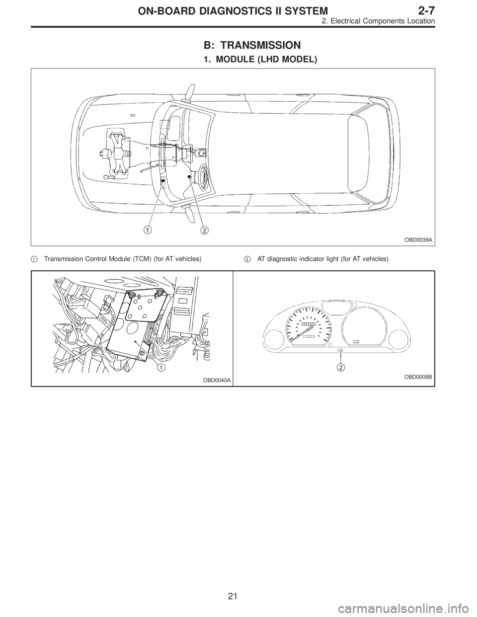
B: TRANSMISSION
1. MODULE (LHD MODEL)
OBD0039A
�1Transmission Control Module (TCM) (for AT vehicles)�2AT diagnostic indicator light (for AT vehicles)
OBD0040AOBD0008B
21
2-7ON-BOARD DIAGNOSTICS II SYSTEM
2. Electrical Components Location
 Remove headlight alarm relay without disconnecting
connector.
2) Measure voltage between headlight alarm relay con-
nector and body.
Connec")