Page 1369 of 2248
 Turn ignition switch to OFF.
2) Connect Subaru Select Monitor or the OBD-II general
scan tool to data link co")
OBD0145A
1CONNECT SUBARU SELECT MONITOR OR
THE OBD-II GENERAL SCAN TOOL, AND
READ DATA.
1) Turn ignition switch to OFF.
2) Connect Subaru Select Monitor or the OBD-II general
scan tool to data link connector.
3) Turn ignition switch to ON and Subaru Select Monitor or
OBD-II general scan tool switch to ON.
4) Start engine.
OBD0185
5) Read data on Subaru Select Monitor or OBD-II general
scan tool.
�Subaru Select Monitor
Designate mode using function key.
Function mode: F10
�F10: Throttle position sensor output signal is indicated.
: Is the voltage less than 0.1 V?
: Go to step 2.
: Go to next.
: Is the voltage more than 4.9 V?
: Go to step 4.
: Even if MIL lights up, the circuit has returned to a
normal condition at this time. A temporary poor
contact of the connector may be the cause. Check
and repair the following connectors.
�Throttle position sensor connector.
�ECM connector
�Coupling connector (B21)
�OBD-II general scan tool
For detailed operation procedures, refer to the OBD-II Gen-
eral Scan Tool Instruction Manual.
163
2-7ON-BOARD DIAGNOSTICS II SYSTEM
11. Diagnostics Chart with Trouble Code
Page 1426 of 2248
 Disconnect connector from knock sensor.
2) Measure resistance of harness between knock sensor
connector and body.
: Connector & terminal
(E14) No. 1—Body/400 kΩ,")
OBD0717A
3
CHECK KNOCK SENSOR.
1) Disconnect connector from knock sensor.
2) Measure resistance of harness between knock sensor
connector and body.
: Connector & terminal
(E14) No. 1—Body/400 kΩ, or less
: Replace knock sensor.
: Repair short circuit of harness between knock
sensor connector and ECM connector.
NOTE:
The harness between both connectors is shielded. Repair
short circuit of harness together with shield.
B2M0625A
4
CHECK INPUT SIGNAL FOR ECM.
1) Connect connectors to ECM and knock sensor.
2) Turn ignition switch to ON.
3) Measure voltage between ECM and body.
: Connector & terminal
(B84) No. 30—Body/2 V, or more
: Repair poor contact in ECM connector.
: Even if MIL lights up, the circuit has returned to a
normal condition at this time. (However, the pos-
sibility of poor contact still remains.)
Check and repair the following connectors.
�Knock sensor connector
�ECM connector
�Coupling connector (B21)
220
2-7ON-BOARD DIAGNOSTICS II SYSTEM
11. Diagnostics Chart with Trouble Code
Page 1477 of 2248
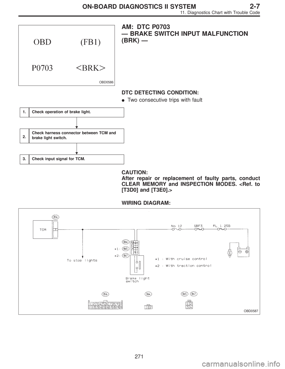
OBD0586
AM: DTC P0703
—BRAKE SWITCH INPUT MALFUNCTION
(BRK)—
DTC DETECTING CONDITION:
�Two consecutive trips with fault
1.Check operation of brake light.
2.Check harness connector between TCM and
brake light switch.
3.Check input signal for TCM.
CAUTION:
After repair or replacement of faulty parts, conduct
CLEAR MEMORY and INSPECTION MODES.
[T3D0] and [T3E0].>
WIRING DIAGRAM:
OBD0587
�
�
271
2-7ON-BOARD DIAGNOSTICS II SYSTEM
11. Diagnostics Chart with Trouble Code
Page 1478 of 2248

1
CHECK OPERATION OF BRAKE LIGHT.
: Depress brake pedal to ensure that brake
light comes on.
: Go to step 2.
: Repair or replace brake light circuit.
OBD0589A
2CHECK HARNESS CONNECTOR BETWEEN
TCM AND BRAKE LIGHT SWITCH.
1) Disconnect connectors from TCM and brake light
switch.
2) Measure resistance of harness connector between
TCM and brake light switch.
: Connector & terminal
(B56) No. 7—(B64) No. 2 / 1Ω, or less
(B56) No. 7—(B65) No. 3 / 1Ω, or less
(With cruise control)
(B56) No. 7—(B67) No. 2 / 1Ω, or less
(With traction control)
: Go to next step.
: Repair or replace harness and connector.
NOTE:
In this case, there is a possibility of open circuit in the har-
ness between the brake light switch connector and TCM
connector.
OBD0590A
3) Measure resistance of harness connector between
TCM and body.
: Connector & terminal
(B56) No. 7—Body / 1 MΩ, or more
: Go to step 3.
: Repair short circuit of harness between TCM con-
nector and body.
272
2-7ON-BOARD DIAGNOSTICS II SYSTEM
11. Diagnostics Chart with Trouble Code
Page 1479 of 2248
OBD0588A
3
CHECK INPUT SIGNAL FOR TCM.
1) Connect connectors to TCM and brake light switch.
2) Measure voltage between TCM and body.
: Connector & terminal
(B56) No. 7—Body / 1 V, or less [When
release the brake pedal.]
(B56) No. 7—Body / 10 V, or more [When
depress the brake pedal.]
: Go to next.
: Adjust or replace brake light switch.
: Is there poor contact in TCM connector?
: Repair poor contact in TCM connector.
: Replace TCM with a new one.
273
2-7ON-BOARD DIAGNOSTICS II SYSTEM
11. Diagnostics Chart with Trouble Code
Page 1480 of 2248
—
OBD0592A
DESCRIPTION:
�The inhibitor switch assures safety when starting the
engine. This switch is mounted on the right")
OBD0591
AN: DTC P0705
—TRANSMISSION RANGE SENSOR CIRCUIT
MALFUNCTION (RNG)—
OBD0592A
DESCRIPTION:
�The inhibitor switch assures safety when starting the
engine. This switch is mounted on the right side of the
transmission case, and is operated by the range selector
lever.
�When the selector lever is set to“P”or“N”, the electri-
cal circuit is connected in the inhibitor switch and the starter
circuit is energized for cracking the engine.
�When the selector lever is set to“R”,“D”,“3”,“2”,or“1”
range, the electrical circuit is disconnected in the inhibitor
switch. Hence engine cranking is disabled. In the“R”
range, the back-up light circuit is completed in the switch,
and the back-up lights come on.
DTC DETECTING CONDITION:
�Two consecutive trips with fault
TROUBLE SYMPTOM:
�Starter does not rotate when selector lever is in“P”or
“N”range.
�Starter rotates when selector lever is in“R”,“D”,“3”,“2”
or“1”range.
�Engine brake is not effected when selector lever is in“3”
range.
�Shift characteristics are erroneous.
274
2-7ON-BOARD DIAGNOSTICS II SYSTEM
11. Diagnostics Chart with Trouble Code
Page 1489 of 2248
OBD0404
AQ: DTC P0725
—ENGINE SPEED INPUT CIRCUIT
MALFUNCTION (ATNE)—
DESCRIPTION:
The engine speed signal is sent to TCM from ECM. This
signal is used for lock-up clutch control and line pressure
control.
DTC DETECTING CONDITION:
�Two consecutive trips with fault
TROUBLE SYMPTOM:
�No lock-up occurs. (after engine warm-up)
�AT diagnostic indicator light (AT OIL TEMP indicator
light) remains on when vehicle speed is“0”.
283
2-7ON-BOARD DIAGNOSTICS II SYSTEM
11. Diagnostics Chart with Trouble Code
Page 1496 of 2248
1.Check any other DTC (besides DTC P0740) on
display.
2.Check duty solenoid B circuit.
[T7B0]”.>
3.Check throttle position sensor circuit.
“3-2 [T7L0]”.>
4.Check vehicle speed sensor 1 circuit.
“3-2 [T7M0]”.>
5.Check vehicle speed sensor 2 circuit.
“3-2 [T7N0]”.>
6.Check engine speed input circuit.
[T7I0]”.>
7.Check inhibitor switch circuit.
DTC P0705 [T11AN0]”.>
8.Check brake light switch circuit.
DTC P0703 [T11AM0]”.>
9.Check ATF temperature sensor circuit.
“3-2 [T7G0]”.>
CAUTION:
After repair or replacement of faulty parts, conduct
CLEAR MEMORY and INSPECTION MODES.
[T3D0] and [T3E0].>
�
�
�
�
�
�
�
�
290
2-7ON-BOARD DIAGNOSTICS II SYSTEM
11. Diagnostics Chart with Trouble Code
 Connect connectors to TCM and brake light switch.
2) Measure voltage between TCM and body.
: Connector & terminal
(B56) No. 7—Body / 1 V, or less [When
rele")
—
DESCRIPTION:
The engine speed signal is sent to TCM from ECM. This
signal is used for lock-up clutch control and line pressure")
![SUBARU LEGACY 1995 Service Repair Manual 1.Check any other DTC (besides DTC P0740) on
display.
2.Check duty solenoid B circuit. <Ref. to“3-2
[T7B0]”.>
3.Check throttle position sensor circuit. <Ref. to
“3-2 [T7L0]”.>
4.Check vehicle](/manual-img/17/57432/w960_57432-1495.png "SUBARU LEGACY 1995 Service Repair Manual 1.Check any other DTC (besides DTC P0740) on
display.
2.Check duty solenoid B circuit. <Ref. to“3-2
[T7B0]”.>
3.Check throttle position sensor circuit. <Ref. to
“3-2 [T7L0]”.>
4.Check vehicle")