Page 2238 of 2248

CHECKING FOR POOR CONTACT ON PLUG-IN CONNECTORS
Most intermittent problems are caused by poor contact of plug-in connectors.
Poor contact is frequently caused by corroded terminals, dirt, foreign substances, weak contact points between
male and female connectors, etc.
To help prevent the replacement of good component parts, sufficiently check the following points.
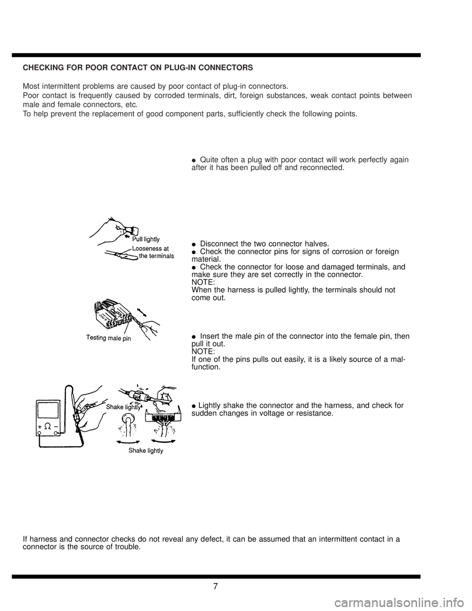
�Quite often a plug with poor contact will work perfectly again
after it has been pulled off and reconnected.
�Disconnect the two connector halves.
�Check the connector pins for signs of corrosion or foreign
material.
�Check the connector for loose and damaged terminals, and
make sure they are set correctly in the connector.
NOTE:
When the harness is pulled lightly, the terminals should not
come out.
�Insert the male pin of the connector into the female pin, then
pull it out.
NOTE:
If one of the pins pulls out easily, it is a likely source of a mal-
function.
�Lightly shake the connector and the harness, and check for
sudden changes in voltage or resistance.
If harness and connector checks do not reveal any defect, it can be assumed that an intermittent contact in a
connector is the source of trouble.
7
Page 2244 of 2248
![SUBARU LEGACY 1995 Service Repair Manual 4-2
[W4D2]
SERVICE
PROCEDURE
4
.
Front
and
Rear
Driv
eShafts
14)
Thus,
disassembly
of
axle
is
completed,
but
UFJ
can-
not
be
disassembled
.
D
:
ASSEMBLY
2
.
FWD
MODEL
Use
specified
grease
.
UFJ SUBARU LEGACY 1995 Service Repair Manual 4-2
[W4D2]
SERVICE
PROCEDURE
4
.
Front
and
Rear
Driv
eShafts
14)
Thus,
disassembly
of
axle
is
completed,
but
UFJ
can-
not
be
disassembled
.
D
:
ASSEMBLY
2
.
FWD
MODEL
Use
specified
grease
.
UFJ](/manual-img/17/57432/w960_57432-2243.png)
4-2
[W4D2]
SERVICE
PROCEDURE
4
.
Front
and
Rear
Driv
eShafts
14)
Thus,
disassembly
of
axle
is
completed,
but
UFJ
can-
not
be
disassembled
.
D
:
ASSEMBLY
2
.
FWD
MODEL
Use
specified
grease
.
UFJ
side
:
UFJ
(Front)
-
NTG2218
(Part
No
.
28093AA020)
DOJ
side
:
AT
model
(Front)
-
VU-3A702
(Yellow)
(Part
No
.
23223GA050)
MT
model
(Front)
-
Molylex
No
.
2
(Part
No
.
723223010)
orSunlight
TB2-A
1)
Place
UFJ
boot
and
small
boot
band
on
UFJ
side
of
shaft
.
CAUTION
:
Be
sure
to
wrap
shaft
splines
with
vinyl
tape
to
prevent
boot
from
scratches
.
2)
Place
drive
shaft
in
a
vise
.
CAUTION
:
Do
not
place
driveshaft
directly
in
the
vise
;
use
wooden
blocks
.
3)
Apply
a
coat
of
specified
grease
[60
to
70g
(2.12to
2
.47oz)]to
UFJ
.
4)
Apply
anevencoat
of
specified
grease
[20
to
30g
(0
.71
to
1
.06oz)]to
the
entire
inner
surface
of
boot
.
Also
apply
grease
to
shaft
.
NOTE
:
The
inside
of
the
larger
end
of
UFJ
boot
and
the
boot
groove
shall
be
cleaned
soas
to
be
free
from
grease
and
other
substances
.
5)
Install
boot
projecting
portion
to
UFJ
groove
.
T
U
FJ
02
Large
boot
band
~3
Boot
6)
Set
large
boot
band
in
place
.
4
Page 2246 of 2248
![SUBARU LEGACY 1995 Service Repair Manual 4-2
[W4D2]
SERVICE
PROCEDURE
4
.
Front
and
Rear
DriveShafts
B4M0228A
I
12)
Install
cage,
which
was
previously
fitted,
to
inner
race
fixed
upon
shaft
.
NOTE
:
Fit
the
cage
with
the
protruded
part SUBARU LEGACY 1995 Service Repair Manual 4-2
[W4D2]
SERVICE
PROCEDURE
4
.
Front
and
Rear
DriveShafts
B4M0228A
I
12)
Install
cage,
which
was
previously
fitted,
to
inner
race
fixed
upon
shaft
.
NOTE
:
Fit
the
cage
with
the
protruded
part](/manual-img/17/57432/w960_57432-2245.png)
4-2
[W4D2]
SERVICE
PROCEDURE
4
.
Front
and
Rear
DriveShafts
B4M0228A
I
12)
Install
cage,
which
was
previously
fitted,
to
inner
race
fixed
upon
shaft
.
NOTE
:
Fit
the
cage
with
the
protruded
part
aligned
with
the
track
on
the
inner
race
and
then
turn
by
a
half
pitch
.
1~
Inner
race
~2
Cage
13)
Put80
to
90g
(2
.82
to
3
.17
oz)
of
specified
grease
into
the
interior
of
DOJ
outer
race
.
14)
Apply
a
coat
of
specified
grease
to
the
cage
pocket
and
six
balls
.
15)
Insert
six
ballsinto
the
cage
pocket
.
16)
Align
the
outer
race
track
and
ball
positions
and
place
in
the
part
where
shaft,
inner
race,
cage
and
balls
are
previously
installed,
and
then
fit
outer
race
.
T
Outer
race
~2
Grease
17)
Install
circlip
in
the
groove
on
DOJ
outer
race
.
NOTE
:
Assure
that
the
balls,
cage
and
inner
race
are
com-
pletely
fitted
in
the
outer
race
of
DOJ
.
*
Exercise
care
not
to
match
the
open
end
of
circlip
in
the
ball
groove
of
outer
race
.
*
Pull
the
shaft
lightly
and
assure
that
the
circlip
is
com-
pletely
fitted
in
the
groove
.
18)
Apply
an
even
coat
of
specified
grease
[20
to
30g
(0
.71
to
1
.06oz)]to
the
entire
inner
surface
of
boot
.
Also
applygrease
to
shaft
.
19)
Install
DOJ
boot
taking
care
not
totwist
it
.
NOTE
:
9
The
inside
of
the
larger
end
of
DOJ
boot
and
the
boot
groove
shall
be
cleaned
soas
to
be
free
from
grease
and
other
substances
.
9
When
installing
DOJ
boot,
position
outer
race
of
DOJ
at
center
of
its
travel
.
20)
Put
a
band
through
the
clip
and
wind
twice
in
align-
ment
with
band
groove
of
boot
.
CAUTION
:
Use
a
new
band
.
21)
Pinch
the
end
of
band
with
pliers
.
Hold
the
clip
and
tighten
securely
.
NOTE
:
When
tightening
boot,
exercise
careso
that
the
air
within
the
boot
is
appropriate
.
6