Page 1621 of 2248

DISPLAY
LED No. Signal name Symbol
1 FWD switch FF
2 Kick-down switch KD
3——
4——
5 Brake BR
6 ABS switch AB
7 Cruise control set CR
8 Power switch PW
9——
10——
FF KD—— ——BR
AB CR PW—— ——
1
2345
678910
P: MODE FA0
—SWITCH 1 (SW1)—
Reference values
�Lights up when the fuse is installed in FWD switch (No. 1).
�Light up when the brake pedal is depressed (No. 5).
�Light up when the ABS signal is entered (No. 6).
�Lights up when the cruise control is set (No. 7).
NOTE:
LED Nos. 2 and 8 do not come on.
DISPLAY
LED No. Signal name Symbol
1 N/P range switch NP
2 R range switch RR
3 D range switch RD
4 3 range switch R3
5 2 range switch R2
6 1 range switch R1
7 Diagnosis switch SS
8——
9——
10——
NP RR RD R3 R2
R1 SS—— —— ——
1
2345
678910
Q: MODE FA1
—SWITCH 2 (SW2)—
Reference values
�Lights up when the N or P range is selected (No. 1).
�Lights up when the R range is selected (No. 2).
�Lights up when the D range is selected (No. 3).
�Lights up when the 3 range is selected (No. 4).
�Lights up when the 2 range is selected (No. 5).
�Lights up when the 1 range is selected (No. 6).
�Lights up when the diagnosis switch is connected
(No. 7).
NOTE:
If each LED does not illuminate in the above conditions,
inhibitor switch malfunction may occur. Perform diagnostics
on inhibitor switch.
66
3-2AUTOMATIC TRANSMISSION AND DIFFERENTIAL
8. Diagnostic Chart with Select Monitor
Page 1626 of 2248

Problem parts
Inhibitor switch
Control module
Vehicle speed sensor 1
Vehicle speed sensor 2
Select cable
Select lever
FWD switch
Starter motor and harness
Throttle position sensor
Diagnosis switch
Accumulator (“N”—“D”)
Accumulator (2A)
Accumulator (4A)
Accumulator (3R)
ATF temperature sensor
Strainer
Duty solenoid A
Duty solenoid B
Shift solenoid 1
Shift solenoid 2
Shift solenoid 3
Control valve
Detent spring
Manual plate
Transfer clutch
Transfer valve
Transfer pipe
Duty solenoid C
Forward clutch
Symptom1234567891011121314151617181920212223242526272829
Engine brake is not effected when select
lever is in“3”or“2”range.
Engine brake is not effected when select
lever is in“1”range.X
Shift characteristics are erroneous.XXXX X X
No lock-up occurs. X X X X
Vehicle cannot be set in“D”range power
mode.XX
“D”range power mode cannot be released. X X X
Parking brake is not effected. X X
Shift lever cannot be moved or is hard to
move from“P”range.XX
Select lever is hard to move. X X X X
Select lever is too light to move (unreason-
able resistance).XX
ATF spurts out.
Differential oil spurts out.
Differential oil level changes excessively.
Odor is produced from oil supply pipe.XX
Shock occurs when select lever is moved
from“1”to“2”range.X XXXX X
Slippage occurs when select lever is moved
from“1”to“2”range.X XXXX X
Shock occurs when select lever is moved
from“2”to“3”range.XXXXXX
Slippage occurs when select lever is moved
from“2”to“3”range.XXXXXX
Shock occurs when select lever is moved
from“3”to“4”range.X X XXX X
Slippage occurs when select lever is moved
from“3”to“4”range.X X XXX X
Shock occurs when select lever is moved
from“3”to“2”range.XXXXX
Shock occurs when select lever is moved
from“D”to“1”range.XXXXX
Shock occurs when select lever is moved
from“2”to“1”range.XXXXX
Shock occurs when accelerator pedal is
released at medium speeds.XXXXX
Vibration occurs during straight-forward
operation.XX
Select lever slips out of position during
acceleration or while driving on rough terrain.XX XX
Vibration occurs during turns (tight corner
“braking”phenomenon).XXX X X XX X
Front wheel slippage occurs during standing
starts.X X X X X X XXXX
Vehicle is not set in FWD mode. X XXX X
1234567891011121314151617181920212223242526272829
71
3-2AUTOMATIC TRANSMISSION AND DIFFERENTIAL
9. General Diagnostic Table
Page 1627 of 2248

One-way clutch (3-")
Overrunning clutch
Drive pinion
Crown gear
Axle shaft
Differential gear
Final gear
Seal pipe
Oil pump
High clutch
Band brake
Low & reverse clutch
Reverse clutch
One-way clutch (1-2)
One-way clutch (3-4)
Double oil seal
Input shaft
Output shaft
Planetary gear
Reduction gear
Drive plate
Torque converter one-way clutch
Lock-up facing
Lock-up damper
ATF deterioration
ATF level too high or too low
Differential gear oil level too high or too low
Engine performance
Engine speed signal
Parking brake mechanism
Problem parts
30 31 32 33 34 35 36 37 38 39 40 41 42 43 44 45 46 47 48 49 50 51 52 53 54 55 56 57 58 Symptom
XEngine brake is not effected when select
lever is in“3”or“2”range.
XEngine brake is not effected when select
lever is in“1”range.
Shift characteristics are erroneous.
X X No lock-up occurs.
Vehicle cannot be set in“D”range power
mode.
“D”range power mode cannot be released.
X Parking brake is not effected.
XShift lever cannot be moved or is hard to
move from“P”range.
Select lever is hard to move.
Select lever is too light to move (unreason-
able resistance).
X ATF spurts out.
X Differential oil spurts out.
X X Differential oil level changes excessively.
X XXXX X XOdor is produced from oil supply pipe.
XXXShock occurs when select lever is moved
from“1”to“2”range.
XSlippage occurs when select lever is moved
from“1”to“2”range.
XX X XShock occurs when select lever is moved
from“2”to“3”range.
XXSlippage occurs when select lever is moved
from“2”to“3”range.
XX XXShock occurs when select lever is moved
from“3”to“4”range.
XSlippage occurs when select lever is moved
from“3”to“4”range.
XX XShock occurs when select lever is moved
from“3”to“2”range.
XShock occurs when select lever is moved
from“D”to“1”range.
XXShock occurs when select lever is moved
from“2”to“1”range.
XXShock occurs when accelerator pedal is
released at medium speeds.
XXVibration occurs during straight-forward
operation.
Select lever slips out of position during
acceleration or while driving on rough terrain.
XVibration occurs during turns (tight corner
“braking”phenomenon).
Front wheel slippage occurs during standing
starts.
Vehicle is not set in FWD mode.
30 31 32 33 34 35 36 37 38 39 40 41 42 43 44 45 46 47 48 49 50 51 52 53 54 55 56 57 58
72
3-2AUTOMATIC TRANSMISSION AND DIFFERENTIAL
9. General Diagnostic Table
Page 1630 of 2248
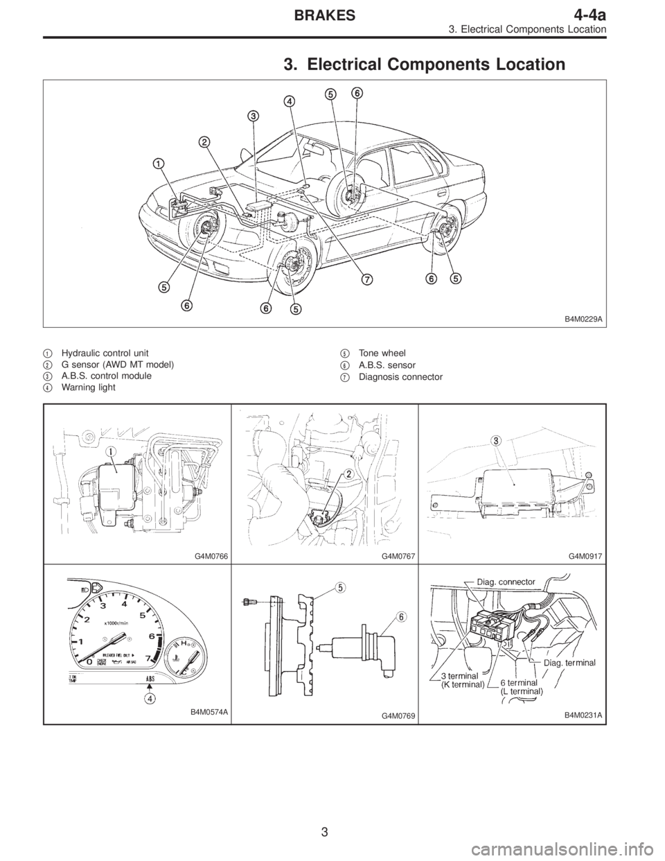
3. Electrical Components Location
B4M0229A
�1Hydraulic control unit
�
2G sensor (AWD MT model)
�
3A.B.S. control module
�
4Warning light�
5Tone wheel
�
6A.B.S. sensor
�
7Diagnosis connector
G4M0766G4M0767G4M0917
B4M0574AG4M0769B4M0231A
3
4-4aBRAKES
3. Electrical Components Location
Page 1631 of 2248
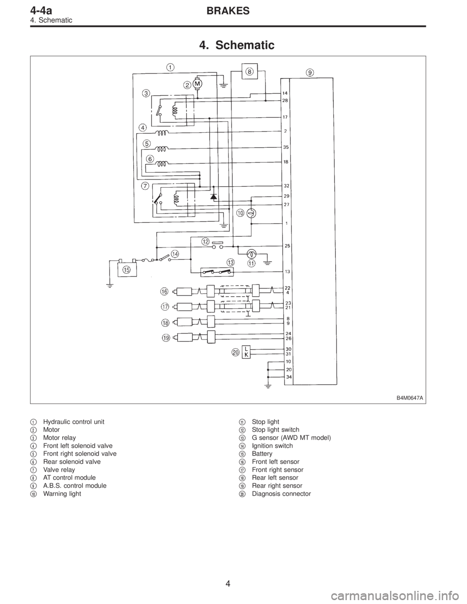
4. Schematic
B4M0647A
�1Hydraulic control unit
�
2Motor
�
3Motor relay
�
4Front left solenoid valve
�
5Front right solenoid valve
�
6Rear solenoid valve
�
7Valve relay
�
8AT control module
�
9A.B.S. control module
�
10Warning light�
11Stop light
�
12Stop light switch
�
13G sensor (AWD MT model)
�
14Ignition switch
�
15Battery
�
16Front left sensor
�
17Front right sensor
�
18Rear left sensor
�
19Rear right sensor
�
20Diagnosis connector
4
4-4aBRAKES
4. Schematic
Page 1632 of 2248

5. Control Module I/O Signal
1. I/O SIGNAL VOLTAGE
G4M0685
ContentsTerminal
No.Ignition
switch ON,
engine
OFFInput/output signals
Measured value Measuring conditions
A.B.S.
sensorFront left wheel 22
0 V 0.12—1V�No. 22—No. 4
(When it is 10 Hz.)
GND 4
Front right wheel 23
0 V 0.12—1V�No. 23—No. 21
(When it is 10 Hz.)
GND 21
Rear left wheel 8
0 V 0.12—1V�No. 8—No. 9
(When it is 10 Hz.)
GND 9
Rear right wheel 24
0 V 0.12—1V�No. 24—No. 26
(When it is 10 Hz.)
GND 26
G sensor (AWD MT model) 13 10—12 V 0 V When slanting about 14°—21.3°(θ)
Diagnosis connector30
—— —
31
Stop light switch 25 0 V 10—12 V When brake pedal is depressed.
Motor monitoring 14 0 V 10—12 V When motor operates.
Valve power supply monitoring 32 10—12 V 10—12 V Ignition switch ON*1
Hydraulic
control
unitSolenoidFront left
wheel210—12 V 0 V
When solenoid is energized to
produce output. Front right
wheel35 10—12 V 0 V
Rear wheel 18 10—12 V 0 V
Valve relay coil 27 0 V 0 V Ignition switch ON*2
Motor relay coil 28 10—12 V 0 VWhen motor operates to produce
output.
Warning light 29 10—12 V 10—12 V Ignition switch ON*3
Power
supplyIgnition 1 10—12 V 10—12 V Ignition switch ON
Relay coil (valve,
motor, etc.)17 10—12 V 10—12 V Ignition switch ON
Grounding line10 0V 0V—
20 0V 0V—
34 0V 0V—
*1: When ignition switch is OFF or the A.B.S. system is inactive: 0 V
*2: When ignition switch is OFF or the A.B.S. system is inactive: 10—12 V
*3: When ignition switch is OFF or the A.B.S. system is inactive, or during 1.5 seconds from ignition switch ON: 0 V
5
4-4aBRAKES
5. Control Module I/O Signal
Page 1634 of 2248
6. Diagnostics Chart for On-board
Diagnosis System
A: BASIC DIAGNOSTICS PROCEDURE
NOTE:
�To check harness for broken wires or short circuits,
shake it while holding it or the connector.
�When A.B.S. warning light illuminates, read and record
trouble code indicated by A.B.S. warning light.
7
4-4aBRAKES
6. Diagnostics Chart for On-board Diagnosis System
Page 1635 of 2248

or more for at least 20 seconds. If a problem is found, the
A.B.S")
B: INSPECTION MODE
The on-board diagnosis system is designed to detect prob-
lems after the vehicle has been driven at 10 km/h (6 MPH)
or more for at least 20 seconds. If a problem is found, the
A.B.S. warning light will illuminate to inform the driver of the
occurrence of a problem. When the warning light is on, the
A.B.S. system will be inactive and the normal braking func-
tion will work. It is possible for a maximum of three trouble
codes to be stored in memory until cleared.
B4M0082A
C: TROUBLE CODES
When on-board diagnosis of the A.B.S. control module
detects a problem, the information (up to a maximum of
three) will be stored in the EEP ROM as a trouble code.
When there are more than three, the most recent three will
be stored. (Stored codes will stay in memory until they are
cleared.)
1. CALLING UP A TROUBLE CODE
1) Take out diagnosis connector from side of driver’s seat
heater unit.
2) Turn ignition switch OFF.
3) Connect diagnosis connector terminal 6 (terminal L) to
diagnosis terminal.
4) Turn ignition switch ON.
5) A.B.S. warning light is set in the diagnostic mode and
blinks to identify trouble code.
6) After the start code (11) is shown, the trouble codes will
be shown in order of the last information first.
These repeat for a maximum of 5 minutes.
NOTE:
When there are no trouble codes in memory, only the start
code (11) is shown.
B4M0232A
8
4-4aBRAKES
6. Diagnostics Chart for On-board Diagnosis System