Page 228 of 2248
 While pushing release lever�
3to pivot and twisting it to
both sides, fit retainer spring�
5onto the constricted portion
of pivot.
NOTE:
Confirm that retaine")
B2M0633A
1. MECHANICAL APPLICATION TYPE
1) While pushing release lever�
3to pivot and twisting it to
both sides, fit retainer spring�
5onto the constricted portion
of pivot.
NOTE:
Confirm that retainer spring is securely fitted by observing
it through the main case hole.
2) Install release bearing�
6and fasten it with two clips�2.
3) Install release lever seal�
4.
G2M0235
4) After remounting engine and transmission on body,
make adjustment of the clutch release lever end play.
CAUTION:
Take care not to twist the cable during adjustment.
5) Install release lever return spring (Models without hill
holder only).
NOTE:
Hook up the return spring to right side hole of the release
lever.
G2M0242
4. Clutch Disc and Cover
A: REMOVAL
1) Install ST on flywheel.
ST 498497100 CRANKSHAFT STOPPER
2) Remove clutch cover and clutch disc.
CAUTION:
�Take care not to allow oil on the clutch disc facing.
�Do not disassemble either clutch cover or clutch
disc.
G2M0243
3) Remove flywheel.
7
2-10SERVICE PROCEDURE
3. Release Bearing and Lever - 4. Clutch Disc and Cover
Page 229 of 2248
 While pushing release lever�
3to pivot and twisting it to
both sides, fit retainer spring�
5onto the constricted portion
of pivot.
NOTE:
Confirm that retaine")
B2M0633A
1. MECHANICAL APPLICATION TYPE
1) While pushing release lever�
3to pivot and twisting it to
both sides, fit retainer spring�
5onto the constricted portion
of pivot.
NOTE:
Confirm that retainer spring is securely fitted by observing
it through the main case hole.
2) Install release bearing�
6and fasten it with two clips�2.
3) Install release lever seal�
4.
G2M0235
4) After remounting engine and transmission on body,
make adjustment of the clutch release lever end play.
CAUTION:
Take care not to twist the cable during adjustment.
5) Install release lever return spring (Models without hill
holder only).
NOTE:
Hook up the return spring to right side hole of the release
lever.
G2M0242
4. Clutch Disc and Cover
A: REMOVAL
1) Install ST on flywheel.
ST 498497100 CRANKSHAFT STOPPER
2) Remove clutch cover and clutch disc.
CAUTION:
�Take care not to allow oil on the clutch disc facing.
�Do not disassemble either clutch cover or clutch
disc.
G2M0243
3) Remove flywheel.
7
2-10SERVICE PROCEDURE
3. Release Bearing and Lever - 4. Clutch Disc and Cover
Page 230 of 2248
B2M0328
B: INSPECTION
1. CLUTCH DISC
1) Facing wear
Measure the depth of rivet head from the surface of facing.
Replace if facings are worn locally or worn down to less
than the specified value.
Depth of rivet head:
Standard value
1.3—1.9 mm (0.051—0.075 in)
Limit of sinking
0.3 mm (0.012 in)
CAUTION:
Do not wash clutch disc with any cleaning fluid.
B2M0329A
2) Hardened facing
Correct by using emery paper or replace.
3) Oil soakage on facing
Replace clutch disc and inspect transmission front oil seal,
transmission case mating surface, engine rear oil seal and
other points for oil leakage.
B2M0330A
4) Deflection on facing
If deflection exceeds the specified value at the outer cir-
cumference of facing, repair or replace.
Limit for deflection:
1.0 mm (0.039 in) at R = 107 mm (4.21 in)
B2M0333A
5) Worn spline, loose rivets and torsion spring failure
Replace defective parts.
8
2-10SERVICE PROCEDURE
4. Clutch Disc and Cover
Page 233 of 2248
")
1. Clutch System
Condition Possible cause and testing Corrective action
1. Clutch slip-
pageIt is hard to perceive clutch slippage in the early stage, but pay attention to the following symptoms.
(a) Engine revs up when shifting.
(b) High speed driving is impossible; especially rapid acceleration impossible and vehicle speed does not increase in
proportion to an increase in engine speed.
(c) Power falls, particularly when ascending a slope, and there is a smell of burning of the clutch facing.
�Method of testing: Put the vehicle in stationary condition with parking brake fully applied. Disengage the clutch and
shift the transmission gear into the first. Gradually allow the clutch to engage while gradually increasing the engine
speed. The clutch function is satisfactory if the engine stalls. However, the clutch is slipping if the vehicle does not
start off and the engine does not stall.
(a) No clutch pedal play Readjust.
(b) No release lever end play Readjust.
(c) Clutch facing smeared by oil Replace.
(d) Worn clutch facing Replace.
(e) Deteriorated diaphragm spring Replace.
(f ) Distorted pressure plate or flywheel Correct or replace.
(g) Defective release bearing holder Correct or replace.
(h) Defective pedal and cable system Correct or replace.
2. Clutch
drags.As a symptom of this trouble, a harsh scratching noise develops and control becomes quite difficult when shifting
gears. The symptom becomes more apparent when shifting into the first gear. However, because much trouble of the
this sort is due to defective synchronization mechanism, carry out the test as described after.
�Method of testing: Refer to DIAGNOSTIC DIAGRAM on page after.
It may be judged as insufficient disengagement of clutch if any noise occurs during this test.
(a) Excessive clutch pedal play Readjust.
(b) Excessive clutch release lever play Readjust.
(c) Worn or rusty clutch disc hub spline Replace clutch disc.
(d) Excessive deflection of clutch disc facing Correct or replace.
(e) Seized crankshaft pilot needle bearing Replace.
(f ) Malfunction of pedal and cable system Correct or replace.
(g) Cracked clutch disc facing Replace.
(h) Sticked clutch disc (smeared by oil or water) Replace.
3. Clutch chat-
ters.Clutch chattering is an unpleasant vibration to the whole body when the vehicle is just started with clutch partially
engaged.
(a) Improper clutch cable routing Correct.
(b) Adhesion of oil on the facing Replace clutch disc.
(c) Weak or broken torsion spring Replace clutch disc.
(d) Defective facing contact or excessive disc Replace clutch disc defection.
(e) Warped pressure plate or flywheel Correct or replace.
(f ) Loose disc rivets Replace clutch disc.
(g) Loose engine mounting Retighten or replace mounting.
(h) Improper adjustment of pitching stopper Adjustment.
11
2-10DIAGNOSTICS
1. Clutch System
Page 235 of 2248
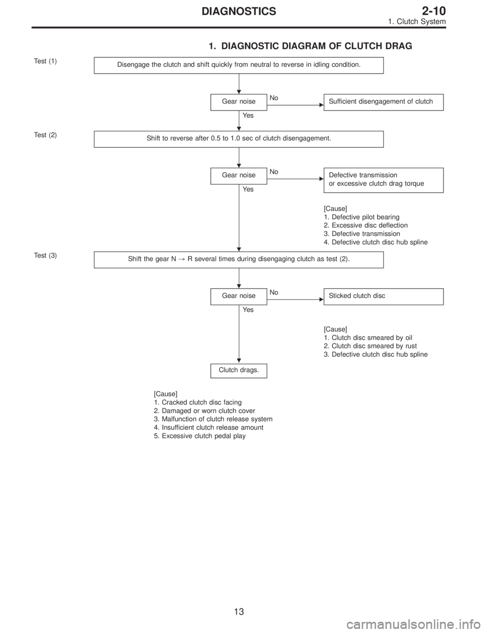
1. DIAGNOSTIC DIAGRAM OF CLUTCH DRAG
Test (1)
Disengage the clutch and shift quickly from neutral to reverse in idling condition.
Gear noise
Ye s
�No
Sufficient disengagement of clutch
Test (2)
Shift to reverse after 0.5 to 1.0 sec of clutch disengagement.
Gear noise
Ye s
�No
Defective transmission
or excessive clutch drag torque
[Cause]
1. Defective pilot bearing
2. Excessive disc deflection
3. Defective transmission
4. Defective clutch disc hub spline
Test (3)
Shift the gear N,R several times during disengaging clutch as test (2).
Gear noise
Ye s
�No
Sticked clutch disc
[Cause]
1. Clutch disc smeared by oil
2. Clutch disc smeared by rust
3. Defective clutch disc hub spline
Clutch drags.
[Cause]
1. Cracked clutch disc facing
2. Damaged or worn clutch cover
3. Malfunction of clutch release system
4. Insufficient clutch release amount
5. Excessive clutch pedal play
�
�
�
�
�
�
13
2-10DIAGNOSTICS
1. Clutch System
Page 237 of 2248
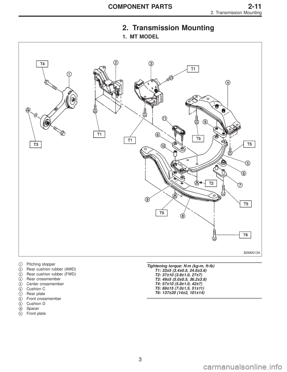
2. Transmission Mounting
1. MT MODEL
B2M0013A
�1Pitching stopper
�
2Rear cushion rubber (AWD)
�
3Rear cushion rubber (FWD)
�
4Rear crossmember
�
5Center crossmember
�
6Cushion C
�
7Rear plate
�
8Front crossmember
�
9Cushion D
�
10Spacer
�
11Front plate
Tightening torque: N⋅m (kg-m, ft-lb)
T1: 33±5 (3.4±0.5, 24.6±3.6)
T2: 37±10 (3.8±1.0, 27±7)
T3: 49±5 (5.0±0.5, 36.2±3.6)
T4: 57±10 (5.8±1.0, 42±7)
T5: 69±15 (7.0±1.5, 51±11)
T6: 137±20 (14±2, 101±14)
3
2-11COMPONENT PARTS
2. Transmission Mounting
Page 238 of 2248
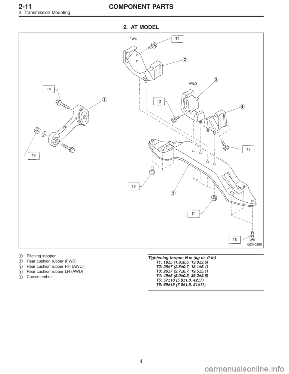
2. AT MODEL
G2M0260
�1Pitching stopper
�
2Rear cushion rubber (FWD)
�
3Rear cushion rubber RH (AWD)
�
4Rear cushion rubber LH (AWD)
�
5Crossmember
Tightening torque: N⋅m (kg-m, ft-lb)
T1: 18±5 (1.8±0.5, 13.0±3.6)
T2: 25±7 (2.5±0.7, 18.1±5.1)
T3: 26±7 (2.7±0.7, 19.5±5.1)
T4: 49±5 (5.0±0.5, 36.2±3.6)
T5: 57±10 (5.8±1.0, 42±7)
T6: 69±15 (7.0±1.5, 51±11)
4
2-11COMPONENT PARTS
2. Transmission Mounting
Page 239 of 2248
1. General Precaution
1) Remove or install engine and transmission in an area
where chain hoists, lifting devices, etc. are available for
ready use.
2) Be sure not to damage coated surfaces of body panels
with tools or stain seats and windows with coolant or oil.
Place a cover over fenders, as required, for protection.
3) Prior to starting work, prepare the following:
Service tools, clean cloth, containers to catch coolant and
oil, wire ropes, chain hoist, transmission jacks, etc.
4) Lift-up or lower the vehicle when necessary. Make sure
to support the correct positions. (Refer to Chapter 1-3
“General Information”.)
5
2-11SERVICE PROCEDURE
1. General Precaution
 Facing wear
Measure the depth of rivet head from the surface of facing.
Replace if facings are worn locally or worn down to less
than the specified value.
Depth")
 Remove or install engine and transmission in an area
where chain hoists, lifting devices, etc. are available for
ready use.
2) Be sure not to damage coated surfaces of body pa")