Page 268 of 2248
B: INSTALLATION
1. Install transmission to engine.
2. Install transmission rear crossmember.
3. Take off transmission jack.
4. Tighten nuts which hold lower side of transmission to engine.
5. Tighten bolt which holds right upper side of transmission to
engine.
AT model
6. Install torque converter to drive plate.
7. Remove special tools.
8. Install pitching stopper.
9. Install front drive shafts into transmission.
10. Install stabilizer clamps onto front crossmember.
11. Install gear shift rod and stay.
�B
�
�
�
�
�
�
�
�
�
�
34
2-11SERVICE PROCEDURE
3. Transmission
Page 269 of 2248
�B
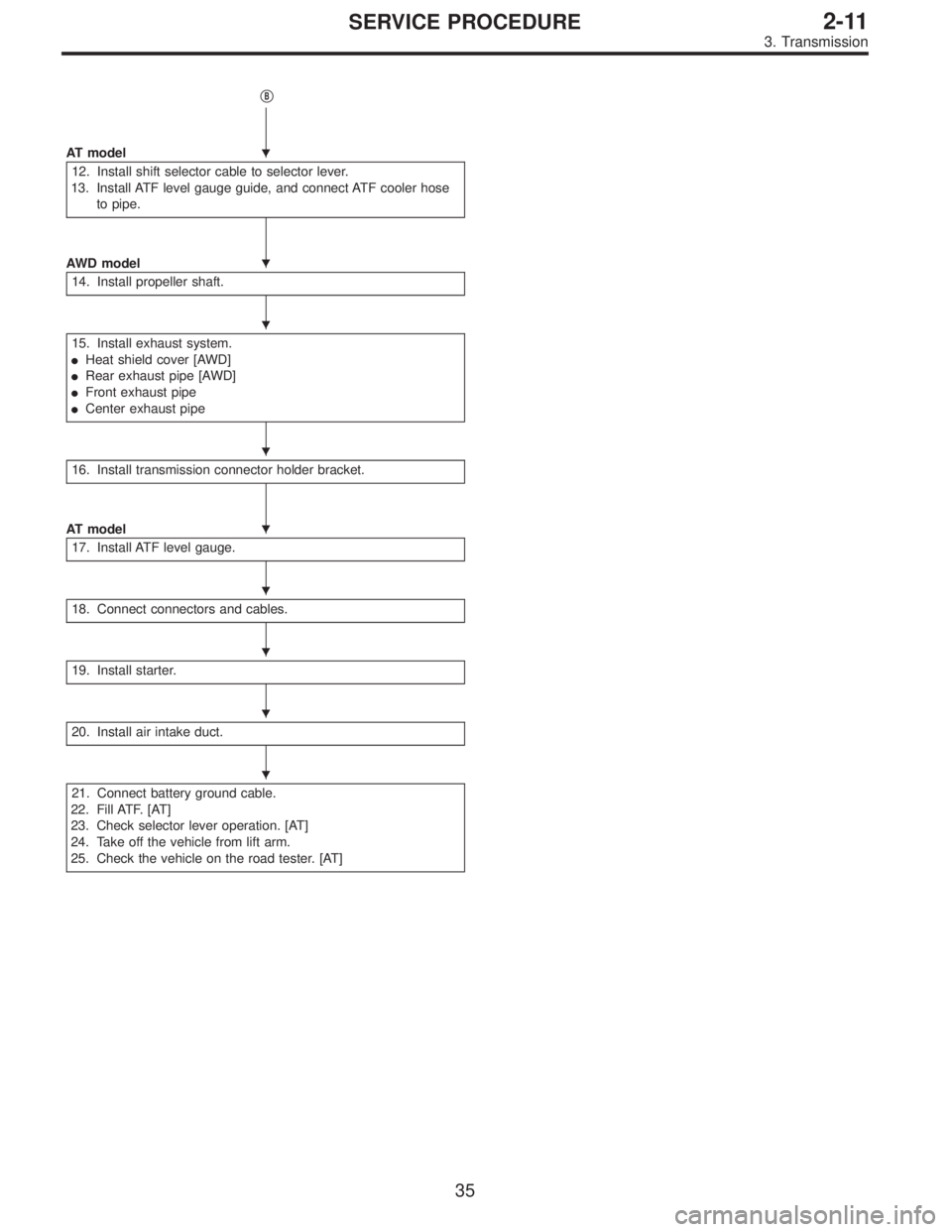
AT model
12. Install shift selector cable to selector lever.
13. Install ATF level gauge guide, and connect ATF cooler hose
to pipe.
AWD model
14. Install propeller shaft.
15. Install exhaust system.
�Heat shield cover [AWD]
�Rear exhaust pipe [AWD]
�Front exhaust pipe
�Center exhaust pipe
16. Install transmission connector holder bracket.
AT model
17. Install ATF level gauge.
18. Connect connectors and cables.
19. Install starter.
20. Install air intake duct.
21. Connect battery ground cable.
22. Fill ATF. [AT]
23. Check selector lever operation. [AT]
24. Take off the vehicle from lift arm.
25. Check the vehicle on the road tester. [AT]
�
�
�
�
�
�
�
�
�
35
2-11SERVICE PROCEDURE
3. Transmission
Page 270 of 2248
B2M0035
1) Install transmission onto engine.
(1) Gradually raise transmission with transmission
jack.
(2) Engage them at splines.
CAUTION:
Be careful not to strike mainshaft against clutch cover.
(MT model)
G2M0832
2) Install transmission rear crossmember.
�MT model
Tightening torque:
T1: 69±15 N⋅m (7.0±1.5 kg-m, 51±11 ft-lb)
T2: 137±20 N⋅m (14±2 kg-m, 101±14 ft-lb)
G2M0332
�AT model
Tightening torque:
T1: 18±5 N⋅m (1.8±0.5 kg-m, 13.0±3.6 ft-lb)
T2: 69±15 N⋅m (7.0±1.5 kg-m, 51±11 ft-lb)
G2M0292
3) Take off transmission jack.
4) Tighten nuts which hold lower side of transmission to
engine.
Tightening torque:
50±4 N⋅m (5.1±0.4 kg-m, 36.9±2.9 ft-lb)
G2M0299
5) Tighten bolt which holds right upper side of transmis-
sion to engine.
Tightening torque:
50±4 N⋅m (5.1±0.4 kg-m, 36.9±2.9 ft-lb)
36
2-11SERVICE PROCEDURE
3. Transmission
Page 271 of 2248
G2M0294
6) Install torque converter to drive plate. (AT model)
(1) Tighten bolts which hold torque converter to drive
plate.
(2) Tighten other bolts while rotating the engine by
using ST.
ST 499977000 CRANK PULLEY WRENCH
CAUTION:
Be careful not to drop bolts into torque converter
housing.
Tightening torque:
25±2 N⋅m (2.5±0.2 kg-m, 18.1±1.4 ft-lb)
(3) Clog plug onto service hole.
B2M0017
(4) Install V-belt cover.
G2M0313
7) Remove special tools.
G2M0302
8) Install pitching stopper.
Tightening torque:
T1: 49±5 N⋅m (5.0±0.5 kg-m, 36.2±3.6 ft-lb)
T2: 57±10 N⋅m (5.8±1.0 kg-m, 42±7 ft-lb)
37
2-11SERVICE PROCEDURE
3. Transmission
Page 272 of 2248
G2M0325
9) Install front drive shafts into transmission.
(1) Lift-up the vehicle.
(2) Install front drive shaft into transmission.
(3) Drive spring pin into chamfered hole of drive shaft.
CAUTION:
Always use a new spring pin.
G2M0324
(4) Install ball joints of lower arm into knuckle arm of
housing, and tighten installing bolts.
Tightening torque:
49±10 N⋅m (5.0±1.0 kg-m, 36±7 ft-lb)
G2M0323
10) Install stabilizer clamps onto front crossmember.
Tightening torque:
25±4 N⋅m (2.5±0.4 kg-m, 18.1±2.9 ft-lb)
G3M0697
11) Install gear shift rod and stay. (MT model)
(1) Install gear shift rod onto transmission.
(2) Install stay onto transmission.
(3) Install spring.
B2M0033A
12) Install shift selector cable onto selector lever. (AT
model)
(1) Install selector cable into selector lever.
(2) Install cable bracket onto body.
NOTE:
Tighten selector cable adjusting and lock nut after check-
ing selector lever operation [step. 24)].
38
2-11SERVICE PROCEDURE
3. Transmission
Page 273 of 2248
G2M0317
13) Install ATF level gauge guide, and ATF cooler hoses
onto pipe. (AT model)
G3M0023
14) Install propeller shaft. (AWD model)
(1) Install propeller shaft into transmission.
(2) Tighten bolts which install propeller shaft onto com-
panion flange of rear differential.
Tightening torque:
31±8 N⋅m (3.2±0.8 kg-m, 23.1±5.8 ft-lb)
G3M0024
(3) Install center bearing bracket on body.
Tightening torque:
52±5 N⋅m (5.3±0.5 kg-m, 38.3±3.6 ft-lb)
G2M0830
15) Install exhaust system.
(1) Install heat shield cover. (AWD model)
G2M0382
(2) Install rear exhaust pipe to muffler. (AWD model)
Tightening torque:
48±9 N⋅m (4.9±0.9 kg-m, 35.4±6.5 ft-lb)
39
2-11SERVICE PROCEDURE
3. Transmission
Page 274 of 2248
B2M0032
(3) Install hanger bracket on right side of transmission.
(AWD model)
G2M0290
(4) Install front exhaust pipe onto engine.
Tightening torque:
30±5 N⋅m (3.1±0.5 kg-m, 22.4±3.6 ft-lb)
G2M0291
(5) Install center exhaust pipe to rear exhaust pipe.
Tightening torque:
18±5 N⋅m (1.8±0.5 kg-m, 13.0±3.6 ft-lb)
B2M0313
(6) Tighten bolt which installs center exhaust pipe to
hanger bracket.
Tightening torque:
30±5 N⋅m (3.1±0.5 kg-m, 22.4±3.6 ft-lb)
B2M0335
(7) Connect connector to rear oxygen sensor.
40
2-11SERVICE PROCEDURE
3. Transmission
Page 275 of 2248
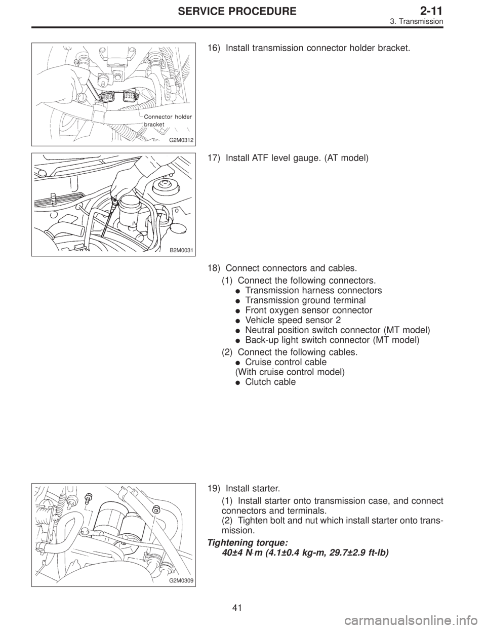
G2M0312
16) Install transmission connector holder bracket.
B2M0031
17) Install ATF level gauge. (AT model)
18) Connect connectors and cables.
(1) Connect the following connectors.
�Transmission harness connectors
�Transmission ground terminal
�Front oxygen sensor connector
�Vehicle speed sensor 2
�Neutral position switch connector (MT model)
�Back-up light switch connector (MT model)
(2) Connect the following cables.
�Cruise control cable
(With cruise control model)
�Clutch cable
G2M0309
19) Install starter.
(1) Install starter onto transmission case, and connect
connectors and terminals.
(2) Tighten bolt and nut which install starter onto trans-
mission.
Tightening torque:
40±4 N⋅m (4.1±0.4 kg-m, 29.7±2.9 ft-lb)
41
2-11SERVICE PROCEDURE
3. Transmission

 Install transmission onto engine.
(1) Gradually raise transmission with transmission
jack.
(2) Engage them at splines.
CAUTION:
Be careful not to strike mainshaft against clutch cover.
(MT")
 Install torque converter to drive plate. (AT model)
(1) Tighten bolts which hold torque converter to drive
plate.
(2) Tighten other bolts while rotating the engine by
using ST.
ST 499977000")
 Install front drive shafts into transmission.
(1) Lift-up the vehicle.
(2) Install front drive shaft into transmission.
(3) Drive spring pin into chamfered hole of drive shaft.
CAUTION:
Alw")
 Install ATF level gauge guide, and ATF cooler hoses
onto pipe. (AT model)
G3M0023
14) Install propeller shaft. (AWD model)
(1) Install propeller shaft into transmission.
(2) Tighten bolts")
 Install hanger bracket on right side of transmission.
(AWD model)
G2M0290
(4) Install front exhaust pipe onto engine.
Tightening torque:
30±5 N⋅m (3.1±0.5 kg-m, 22.4±3.6 ft-lb)
G2M029")