Page 310 of 2248
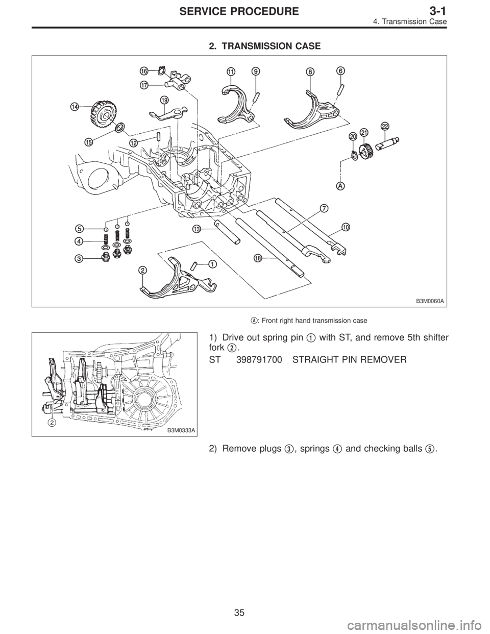
2. TRANSMISSION CASE
B3M0060A
�A: Front right hand transmission case
B3M0333A
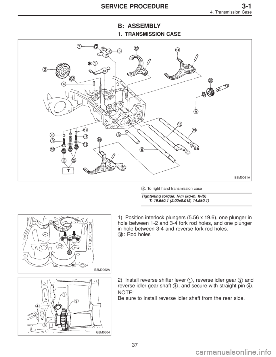
1) Drive out spring pin�1with ST, and remove 5th shifter
fork�
2.
ST 398791700 STRAIGHT PIN REMOVER
2) Remove plugs�
3, springs�4and checking balls�5.
35
3-1SERVICE PROCEDURE
4. Transmission Case
Page 311 of 2248
 Drive out spring pin�6, and pull out 3-4 fork rod�7and
shifter fork�
8.
NOTE:
When removing rod, keep other rods in neutral. Also, when
pulling out straight pin, remove it toward inside of")
B3M0333B
3) Drive out spring pin�6, and pull out 3-4 fork rod�7and
shifter fork�
8.
NOTE:
When removing rod, keep other rods in neutral. Also, when
pulling out straight pin, remove it toward inside of case so
that it may not hit against case.
4) Drive out straight pin�
9, and pull out 1-2 fork rod�10and
shifter fork�
11.
G3M0602
5) Pull out straight pin�12, and remove idler gear shaft�13,
reverse idler gear�
14and washer�15.
6) Remove outer snap ring�
16, and pull out reverse shifter
rod arm�
17from reverse fork rod�18. Then take out ball,
spring and interlock plunger from rod.
And then remove rod.
NOTE:
When pulling out reverse shifter rod arm, be careful not to
let ball pop out of arm.
7) Remove reverse shifter lever�
19.
G3M0546
8) Remove differential side retainers using ST.
ST 499787000 WRENCH ASSY
G3M0547
9) Remove outer snap ring�20and pull out speedometer
driven gear�
21. Next, remove vehicle speed sensor 2, oil
seal, speedometer shaft�
22and washer.
36
3-1SERVICE PROCEDURE
4. Transmission Case
Page 312 of 2248
B: ASSEMBLY
1. TRANSMISSION CASE
B3M0061A
�A: To right hand transmission case
Tightening torque: N⋅m (kg-m, ft-lb)
T: 19.6±0.1 (2.00±0.015, 14.5±0.1)
B3M0062A
1) Position interlock plungers (5.56 x 19.6), one plunger in
hole between 1-2 and 3-4 fork rod holes, and one plunger
in hole between 3-4 and reverse fork rod holes.
�
B: Rod holes
G3M0604
2) Install reverse shifter lever�1, reverse idler gear�2and
reverse idler gear shaft�
3, and secure with straight pin�4.
NOTE:
Be sure to install reverse idler shaft from the rear side.
37
3-1SERVICE PROCEDURE
4. Transmission Case
Page 313 of 2248
3) Install reverse arm fork spring, ball and interlock
plunger (5.56 x 19.6) to reverse fork rod arm�
5. Insert
reverse fork rod�
6into hole in reverse fork rod arm�5, and
hold it with outer snap ring�
7using ST.
ST 399411700 ACCENT BALL INSTALLER
CAUTION:
Apply grease to plunger to prevent it from falling.
4) Position ball�
8(7.1438), spring�9and gasket�10in
reverse shifter rod hole, on left side transmission case, and
tighten checking ball plug�
11.
CAUTION:
Replace gasket with a new one.
G3M0796
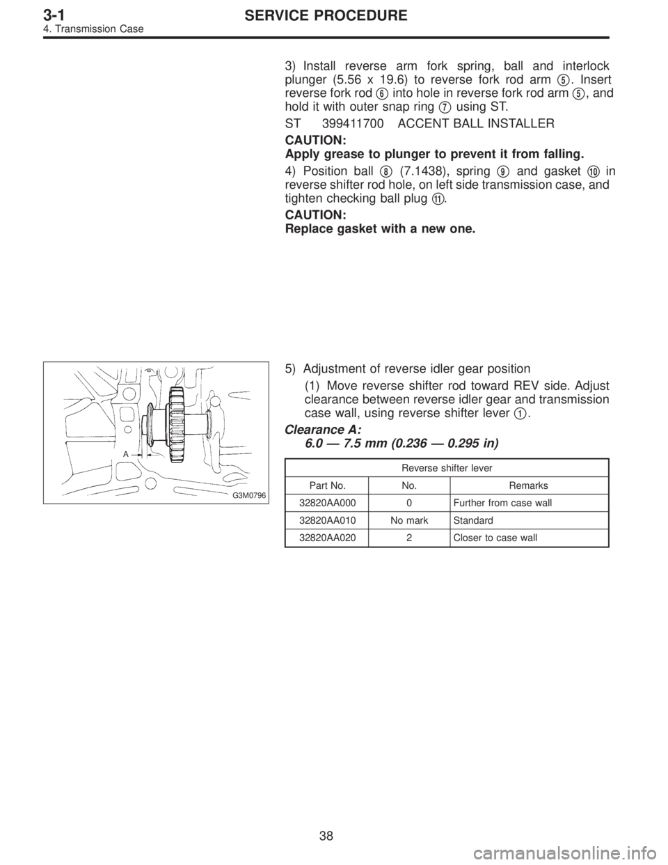
5) Adjustment of reverse idler gear position
(1) Move reverse shifter rod toward REV side. Adjust
clearance between reverse idler gear and transmission
case wall, using reverse shifter lever�
1.
Clearance A:
6.0—7.5 mm (0.236—0.295 in)
Reverse shifter lever
Part No. No. Remarks
32820AA000 0 Further from case wall
32820AA010 No mark Standard
32820AA020 2 Closer to case wall
38
3-1SERVICE PROCEDURE
4. Transmission Case
Page 314 of 2248
 After installing a suitable reverse shifter lever, shift
into neutral. Using a thickness gauge, measure clear-
ance between reverse idler gear and transmission case
wall and adjust with wa")
B3M0063
(2) After installing a suitable reverse shifter lever, shift
into neutral. Using a thickness gauge, measure clear-
ance between reverse idler gear and transmission case
wall and adjust with washer(s).
Clearance:
0—0.5 mm (0—0.020 in)
Washer (20.5 x 26 x t)
Part No. Thickness mm (in)
803020151 0.4 (0.016)
803020152 1.1 (0.043)
803020153 1.5 (0.059)
803020154 1.9 (0.075)
803020155 2.3 (0.091)
B3M0333C
6) Installation of 1-2 shifter fork�12and rod�13
(1) Install 1-2 fork rod into 1-2 shifter fork via the hole
on the rear of transmission case.
(2) Align the holes in rod and fork, and drive straight
pin (6 x 22) into these holes using ST.
ST 398791700 STRAIGHT PIN REMOVER
NOTE:
�Set other rods to neutral.
�Make sure interlock plunger (5.56 x 19.6) is on the 3-4
fork rod side.
7) Installation of 3-4 shifter fork�
14and rod�15
(1) Install interlock plunger (3 x 11.9) onto 3-4 fork rod.
CAUTION:
Apply a coat of grease to plunger to prevent it from
falling.
(2) Install 3-4 fork rod into 3-4 shifter fork via the hole
on the rear of transmission case.
(3) Align the holes in rod and fork, and drive straight
pin (6 x 22) into these holes.
ST 398791700 STRAIGHT PIN REMOVER
NOTE:
�Set reverse fork rod to neutral.
�Make sure interlock plunger (installed before) is on the
reverse fork rod side.
8) Install 5th shifter fork�
16onto the rear of reverse fork rod
�
6. Align holes in the two parts and drive straight pin into
place.
ST 398791700 STRAIGHT PIN REMOVER
39
3-1SERVICE PROCEDURE
4. Transmission Case
Page 315 of 2248
G3M0552
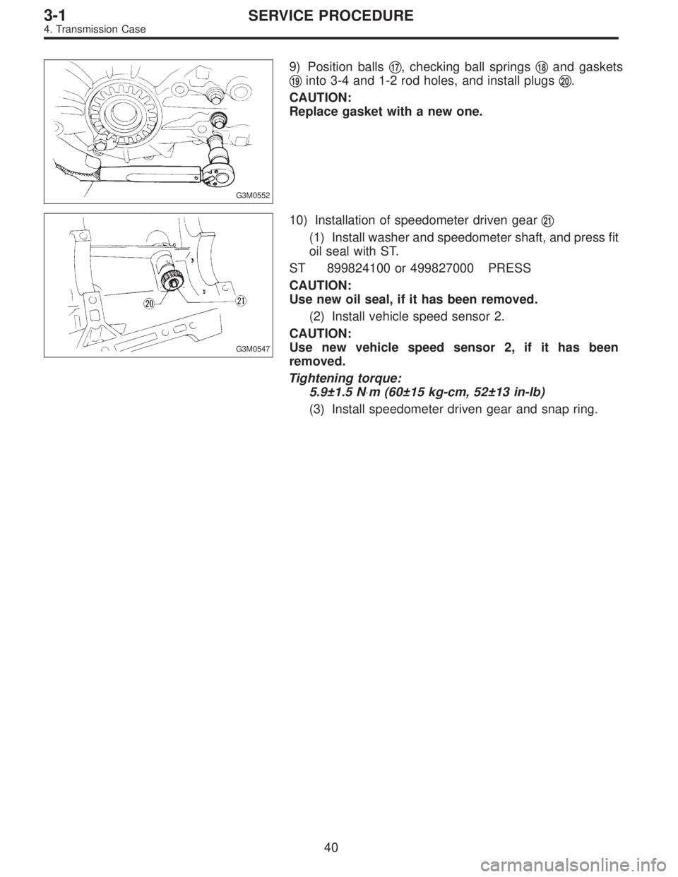
9) Position balls�17, checking ball springs�18and gaskets
�
19into 3-4 and 1-2 rod holes, and install plugs�20.
CAUTION:
Replace gasket with a new one.
G3M0547
10) Installation of speedometer driven gear�21
(1) Install washer and speedometer shaft, and press fit
oil seal with ST.
ST 899824100 or 499827000 PRESS
CAUTION:
Use new oil seal, if it has been removed.
(2) Install vehicle speed sensor 2.
CAUTION:
Use new vehicle speed sensor 2, if it has been
removed.
Tightening torque:
5.9±1.5 N⋅m (60±15 kg-cm, 52±13 in-lb)
(3) Install speedometer driven gear and snap ring.
40
3-1SERVICE PROCEDURE
4. Transmission Case
Page 316 of 2248
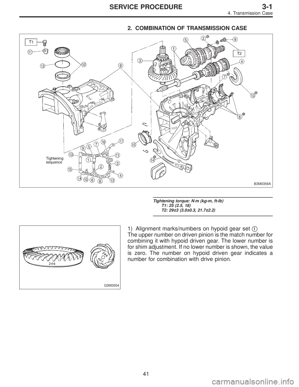
2. COMBINATION OF TRANSMISSION CASE
B3M0356A
Tightening torque: N⋅m (kg-m, ft-lb)
T1: 25 (2.5, 18)
T2: 29±3 (3.0±0.3, 21.7±2.2)
G3M0554
1) Alignment marks/numbers on hypoid gear set�1
The upper number on driven pinion is the match number for
combining it with hypoid driven gear. The lower number is
for shim adjustment. If no lower number is shown, the value
is zero. The number on hypoid driven gear indicates a
number for combination with drive pinion.
41
3-1SERVICE PROCEDURE
4. Transmission Case
Page 317 of 2248
 Adjustment of drive pinion shim�2
(1) Place drive pinion shaft assembly on right hand
transmission main case without shim and tighten bear-
ing mounting bolts.
(2) Inspection and adjustmen")
B3M0064A
2) Adjustment of drive pinion shim�2
(1) Place drive pinion shaft assembly on right hand
transmission main case without shim and tighten bear-
ing mounting bolts.
(2) Inspection and adjustment of ST
NOTE:
�Loosen the two bolts and adjust so that the scale indi-
cates 0.5 correctly when the plate end and the scale end
are on the same level.
�Tighten the two bolts.
ST 499917500 DRIVE PINION GAUGE ASSY
�
A: Plate
�
B: Scale
B3M0065A
(3) Position the ST by inserting the knock pin of ST into
the knock hole in the transmission case.
(4) Slide the drive pinion gauge scale with finger tip
and read the value at the point where it matches with
the end face of drive pinion.
�
C: Adjust clearance to zero without shim.
(5) The thickness of shim shall be determined by add-
ing the value indicated on drive pinion to the value
indicated on the ST. (Add if the number on drive pinion
is prefixed by + and subtract if the number is prefixed
by�.)
ST 499917500 DRIVE PINION GAUGE ASSY
Select one to three shims from the next table for the value
determined as described above and take a shim thickness
which is closest to the said value.
Drive pinion shim
Part No. Thickness mm (in)
32295AA031 0.150 (0.0059)
32295AA041 0.175 (0.0069)
32295AA051 0.200 (0.0079)
32295AA061 0.225 (0.0089)
32295AA071 0.250 (0.0098)
32295AA081 0.275 (0.0108)
32295AA091 0.300 (0.0118)
32295AA101 0.500 (0.0197)
42
3-1SERVICE PROCEDURE
4. Transmission Case