Page 290 of 2248
1. General
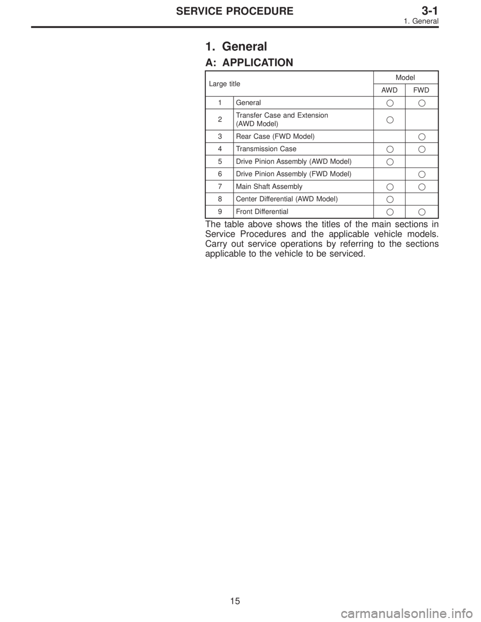
A: APPLICATION
Large titleModel
AWD FWD
1 General��
2Transfer Case and Extension
(AWD Model)�
3 Rear Case (FWD Model)�
4 Transmission Case��
5 Drive Pinion Assembly (AWD Model)�
6 Drive Pinion Assembly (FWD Model)�
7 Main Shaft Assembly��
8 Center Differential (AWD Model)�
9 Front Differential��
The table above shows the titles of the main sections in
Service Procedures and the applicable vehicle models.
Carry out service operations by referring to the sections
applicable to the vehicle to be serviced.
15
3-1SERVICE PROCEDURE
1. General
Page 291 of 2248
 The following job should be followed before disassem-
bly:
(1) Clean oil, grease, dirt and dust from transmission.
(2) Remove drain plug�
1to drain oil. After draining,
reti")
B3M0037A
B: PRECAUTIONS
1) The following job should be followed before disassem-
bly:
(1) Clean oil, grease, dirt and dust from transmission.
(2) Remove drain plug�
1to drain oil. After draining,
retighten it as before.
CAUTION:
Replace gasket with a new one.
Tightening torque:
44±3 N⋅m (4.5±0.3 kg-m, 32.5±2.2 ft-lb)
G3M0517
(3) Attach transmission to ST.
ST 499937100 TRANSMISSION STAND SET
2) Rotating parts should be coated with oil prior to assem-
bly.
3) All disassembled parts, if to be reused, should be rein-
stalled in the original positions and directions.
4) Gaskets and lock washers must be replaced with new
ones.
5) Liquid gasket should be used where specified to pre-
vent leakage.
6) Fill transmission gear oil through the oil level gauge
hole up to upper point level gauge.
C: INSPECTION
Disassembled parts should be washed clean first and then
inspected carefully.
1) Bearings
Replace bearings in the following cases:
�Bearings whose balls, outer races and inner races are
broken or rusty.
�Worn bearings
�Bearings that fail to turn smoothly or make abnormal
noise when turned after gear oil lubrication.
B3M0038A
The ball bearing�3on the rear side of the drive pinion shaft
�
2should be checked for smooth rotation before the drive
pinion assembly is disassembled. In this case, because a
preload is working on the bearing, its rotation feels like it is
slightly dragging unlike the other bearings.
�Bearings having other defects
16
3-1SERVICE PROCEDURE
1. General
Page 294 of 2248
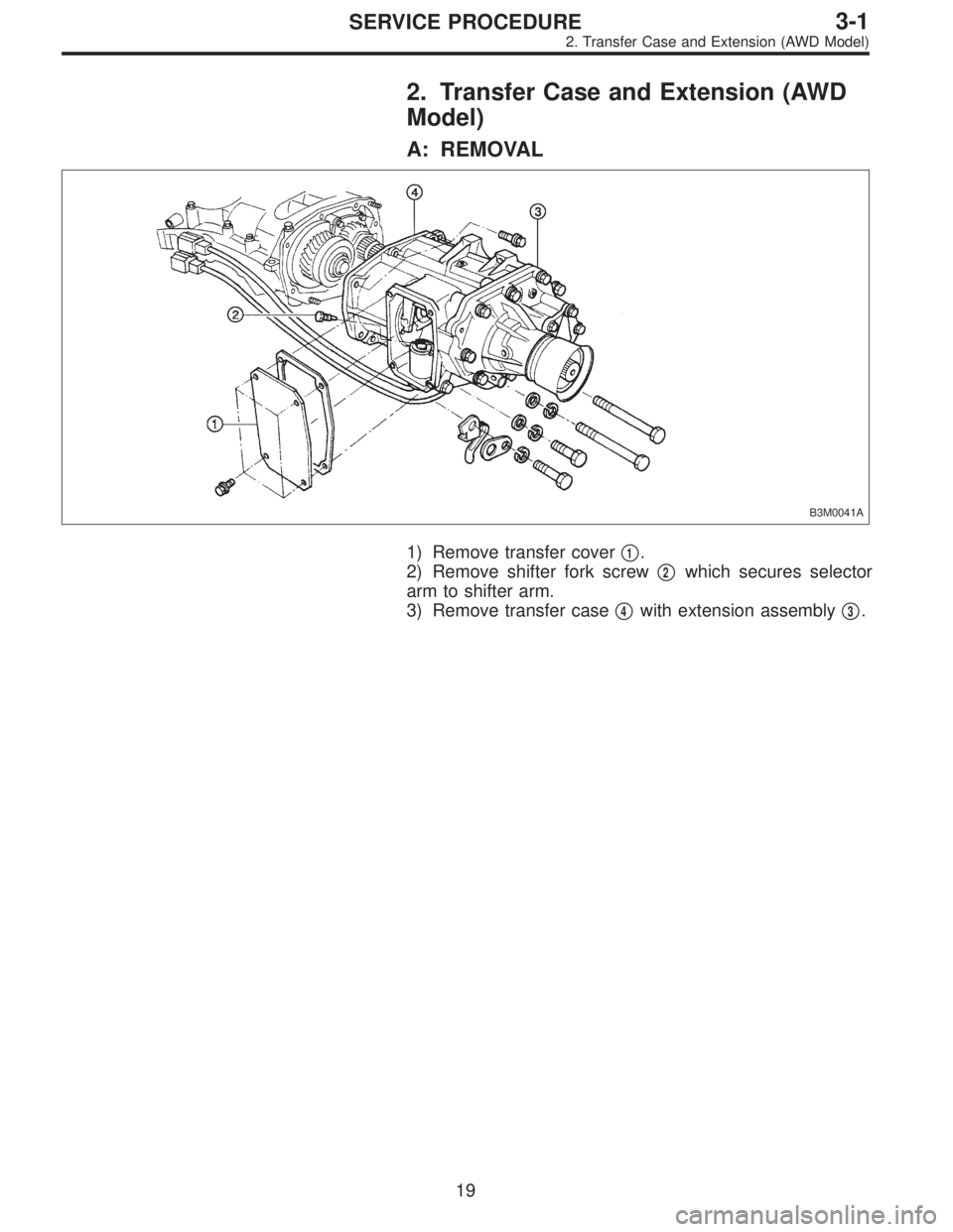
2. Transfer Case and Extension (AWD
Model)
A: REMOVAL
B3M0041A
1) Remove transfer cover�1.
2) Remove shifter fork screw�
2which secures selector
arm to shifter arm.
3) Remove transfer case�
4with extension assembly�3.
19
3-1SERVICE PROCEDURE
2. Transfer Case and Extension (AWD Model)
Page 295 of 2248
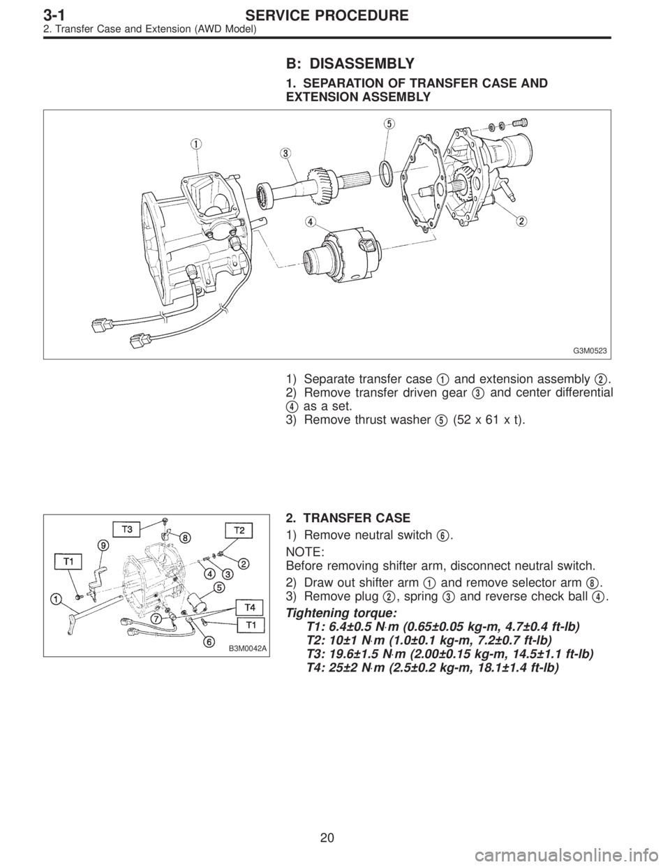
B: DISASSEMBLY
1. SEPARATION OF TRANSFER CASE AND
EXTENSION ASSEMBLY
G3M0523
1) Separate transfer case�1and extension assembly�2.
2) Remove transfer driven gear�
3and center differential
�
4as a set.
3) Remove thrust washer�
5(52x61xt).
B3M0042A
2. TRANSFER CASE
1) Remove neutral switch�
6.
NOTE:
Before removing shifter arm, disconnect neutral switch.
2) Draw out shifter arm�
1and remove selector arm�8.
3) Remove plug�
2, spring�3and reverse check ball�4.
Tightening torque:
T1: 6.4±0.5 N⋅m (0.65±0.05 kg-m, 4.7±0.4 ft-lb)
T2: 10±1 N⋅m (1.0±0.1 kg-m, 7.2±0.7 ft-lb)
T3: 19.6±1.5 N⋅m (2.00±0.15 kg-m, 14.5±1.1 ft-lb)
T4: 25±2 N⋅m (2.5±0.2 kg-m, 18.1±1.4 ft-lb)
20
3-1SERVICE PROCEDURE
2. Transfer Case and Extension (AWD Model)
Page 296 of 2248
B3M0043A
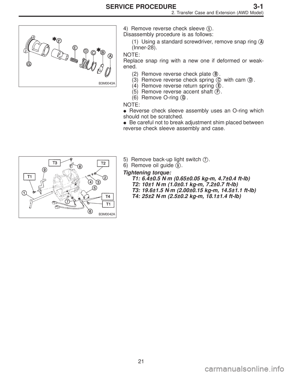
4) Remove reverse check sleeve�5.
Disassembly procedure is as follows:
(1) Using a standard screwdriver, remove snap ring�
A
(Inner-28).
NOTE:
Replace snap ring with a new one if deformed or weak-
ened.
(2) Remove reverse check plate�
B.
(3) Remove reverse check spring�
Cwith cam�D.
(4) Remove reverse return spring�
E.
(5) Remove reverse accent shaft�
F.
(6) Remove O-ring�
G.
NOTE:
�Reverse check sleeve assembly uses an O-ring which
should not be scratched.
�Be careful not to break adjustment shim placed between
reverse check sleeve assembly and case.
B3M0042A
5) Remove back-up light switch�7.
6) Remove oil guide�
9.
Tightening torque:
T1: 6.4±0.5 N⋅m (0.65±0.05 kg-m, 4.7±0.4 ft-lb)
T2: 10±1 N⋅m (1.0±0.1 kg-m, 7.2±0.7 ft-lb)
T3: 19.6±1.5 N⋅m (2.00±0.15 kg-m, 14.5±1.1 ft-lb)
T4: 25±2 N⋅m (2.5±0.2 kg-m, 18.1±1.4 ft-lb)
21
3-1SERVICE PROCEDURE
2. Transfer Case and Extension (AWD Model)
Page 297 of 2248
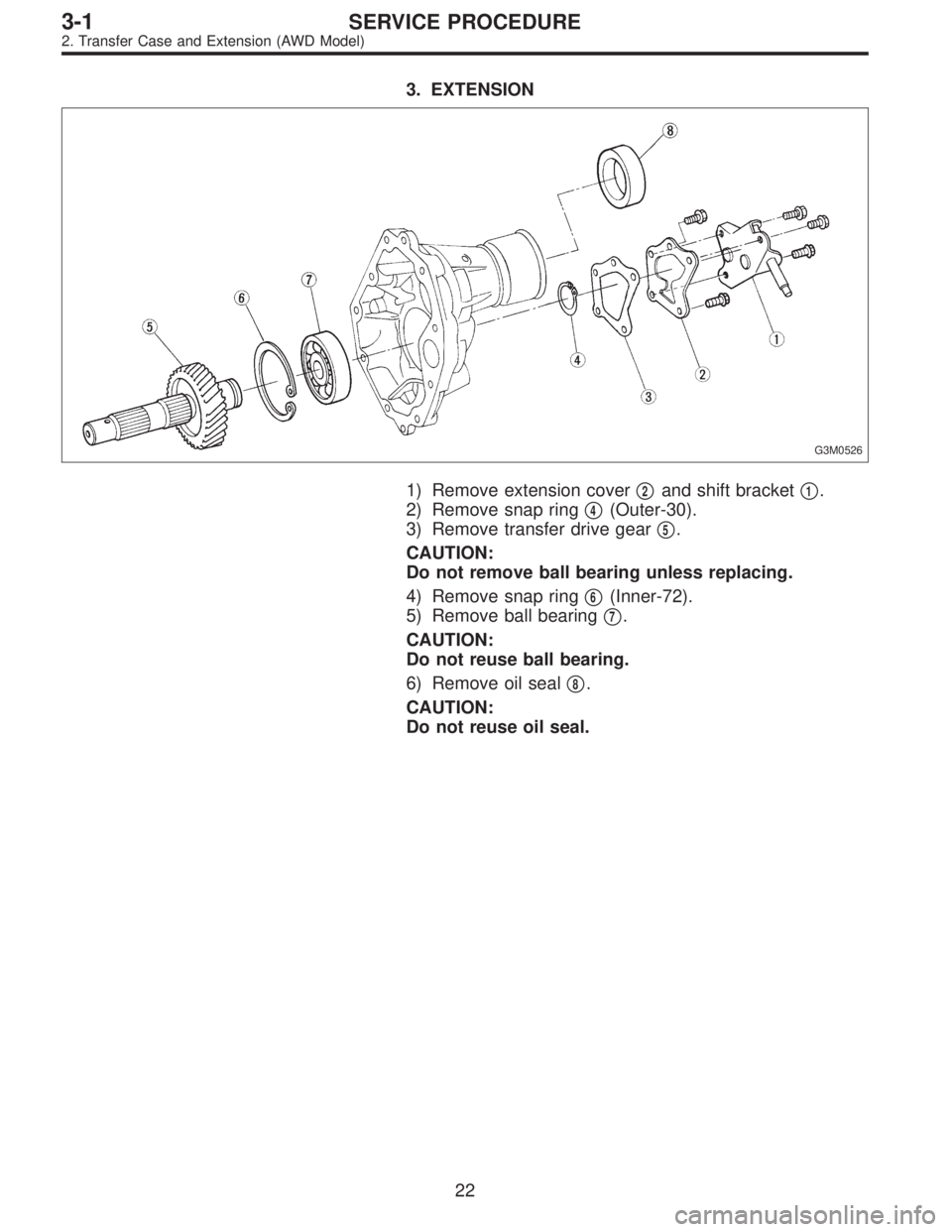
3. EXTENSION
G3M0526
1) Remove extension cover�2and shift bracket�1.
2) Remove snap ring�
4(Outer-30).
3) Remove transfer drive gear�
5.
CAUTION:
Do not remove ball bearing unless replacing.
4) Remove snap ring�
6(Inner-72).
5) Remove ball bearing�
7.
CAUTION:
Do not reuse ball bearing.
6) Remove oil seal�
8.
CAUTION:
Do not reuse oil seal.
22
3-1SERVICE PROCEDURE
2. Transfer Case and Extension (AWD Model)
Page 298 of 2248
C: ASSEMBLY
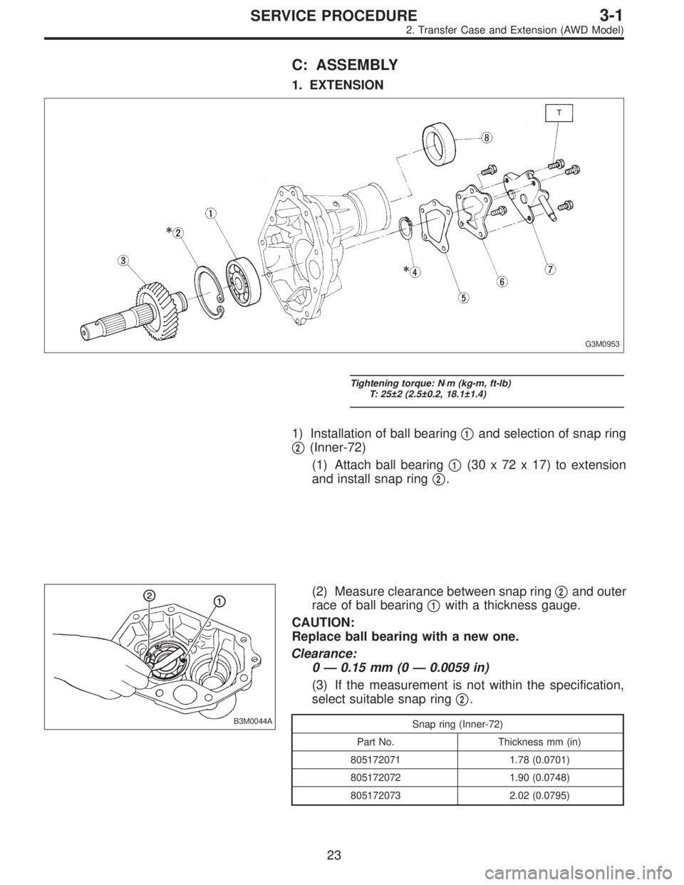
1. EXTENSION
G3M0953
Tightening torque: N⋅m (kg-m, ft-lb)
T: 25±2 (2.5±0.2, 18.1±1.4)
1) Installation of ball bearing�1and selection of snap ring
�
2(Inner-72)
(1) Attach ball bearing�
1(30 x 72 x 17) to extension
and install snap ring�
2.
B3M0044A
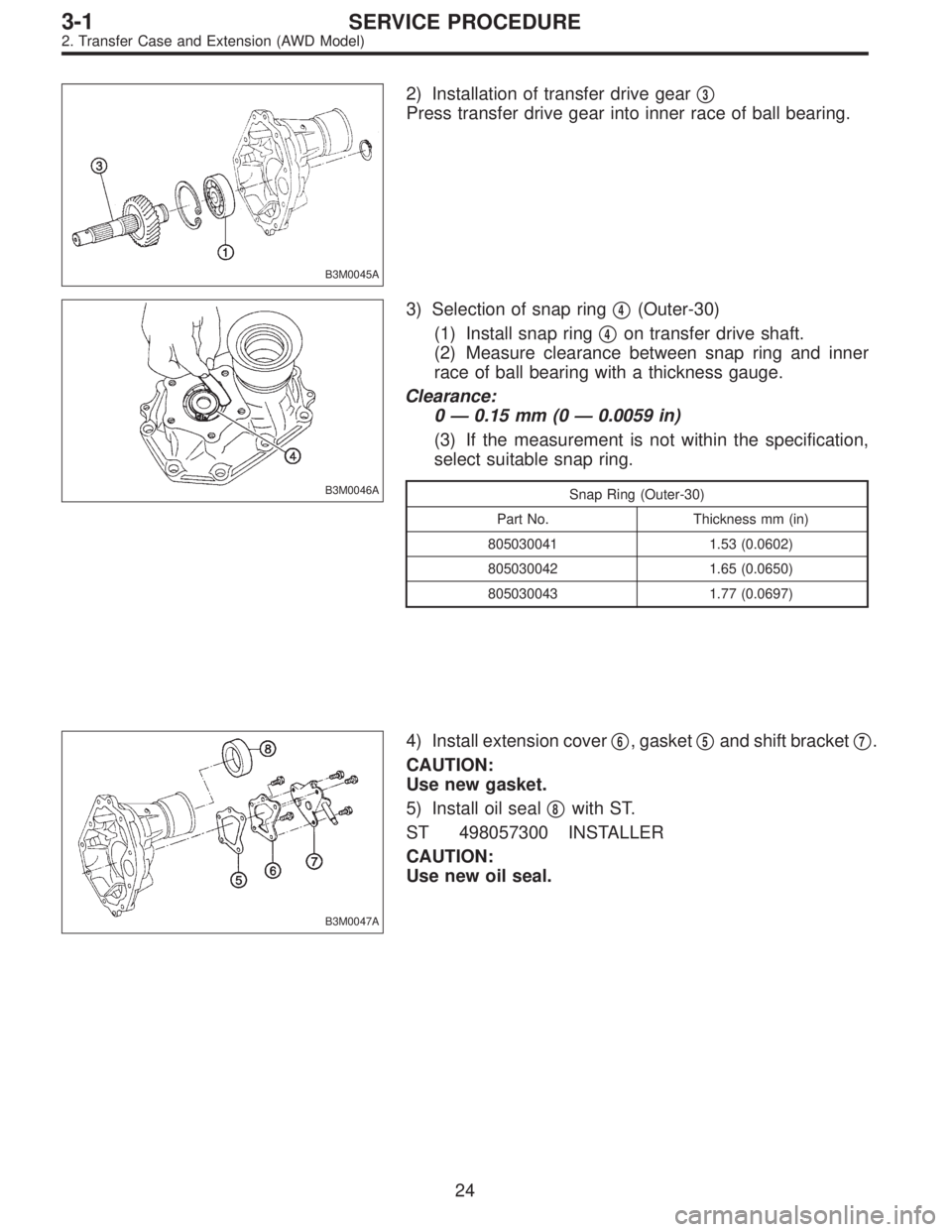
(2) Measure clearance between snap ring�2and outer
race of ball bearing�
1with a thickness gauge.
CAUTION:
Replace ball bearing with a new one.
Clearance:
0—0.15 mm (0—0.0059 in)
(3) If the measurement is not within the specification,
select suitable snap ring�
2.
Snap ring (Inner-72)
Part No. Thickness mm (in)
805172071 1.78 (0.0701)
805172072 1.90 (0.0748)
805172073 2.02 (0.0795)
23
3-1SERVICE PROCEDURE
2. Transfer Case and Extension (AWD Model)
Page 299 of 2248
B3M0045A
2) Installation of transfer drive gear�3
Press transfer drive gear into inner race of ball bearing.
B3M0046A
3) Selection of snap ring�4(Outer-30)
(1) Install snap ring�
4on transfer drive shaft.
(2) Measure clearance between snap ring and inner
race of ball bearing with a thickness gauge.
Clearance:
0—0.15 mm (0—0.0059 in)
(3) If the measurement is not within the specification,
select suitable snap ring.
Snap Ring (Outer-30)
Part No. Thickness mm (in)
805030041 1.53 (0.0602)
805030042 1.65 (0.0650)
805030043 1.77 (0.0697)
B3M0047A
4) Install extension cover�6, gasket�5and shift bracket�7.
CAUTION:
Use new gasket.
5) Install oil seal�
8with ST.
ST 498057300 INSTALLER
CAUTION:
Use new oil seal.
24
3-1SERVICE PROCEDURE
2. Transfer Case and Extension (AWD Model)