Page 318 of 2248
 Install differential assembly�3on left hand transmission
case.
CAUTION:
Be careful not to fold the sealing lip of oil seal.
NOTE:
Wrap the left and right splined sections of axle shaft with")
G3M0557
3) Install differential assembly�3on left hand transmission
case.
CAUTION:
Be careful not to fold the sealing lip of oil seal.
NOTE:
Wrap the left and right splined sections of axle shaft with
vinyl tape to prevent scratches.
G3M0558
4) Install needle bearing and oil seal onto the front of
transmission main shaft assembly�
4, and position in left
side transmission case.
CAUTION:
�Wrap clutch splined section with vinyl tape to pre-
vent damage to oil seal.
�Apply grease (Unilube #2 or equivalent) to the seal-
ing lip of oil seal.
NOTE:
�Align the end face of seal with surface A of left side
transmission main case when installing oil seal.
�Be careful not to drop oil seal when installing right side
transmission main case.
�Make sure straight pin is positioned in hole in needle
bearing’s outer race.
G3M0575
5) Install drive pinion shaft assembly�5with shims
selected before into transmission case.
NOTE:
Ensure that the knock pin of the case is fitted into the hole
in the bearing outer race.
43
3-1SERVICE PROCEDURE
4. Transmission Case
Page 319 of 2248
 Selection of suitable 1st-2nd, 3rd-4th and 5th shifter
fork
Set transmission main shaft assembly and drive pinion
shaft assembly in position (so there is no clearance
bet")
B3M0066A
B3M0067A
B3M0068A
6) Selection of suitable 1st-2nd, 3rd-4th and 5th shifter
fork
Set transmission main shaft assembly and drive pinion
shaft assembly in position (so there is no clearance
between the two when moved all the way to the front).
Select suitable 1st-2nd, 3rd-4th and 5th shifter fork so that
coupling sleeve and reverse driven gear are positioned in
the center of their synchronizing mechanisms.
Clearance mm (in)
1st driven gear�
Ato reverse driven gear�B�a: 9.5 (0.374)
2nd driven gear�
Cto reverse driven gear�B�b: 9.5 (0.374)
3rd drive gear�
Dto coupling sleeve�E�c: 9.3 (0.366)
4th drive gear�
Fto coupling sleeve�E�d: 9.3 (0.366)
5th drive gear�
Gto coupling sleeve�H�e: 9.3 (0.366)
1st-2nd shifter fork
Part No. No. Remarks
32804AA060 1Approach to 1st gear by
0.2 mm (0.008 in)
32804AA070No
markStandard
32804AA080 3Approach to 2nd gear by
0.2 mm (0.008 in)
3rd-4th shifter fork
Part No. No. Remarks
32810AA060 1Approach to 4th gear by
0.2 mm (0.008 in)
32810AA070No
markStandard
32810AA100 3Approach to 3rd gear by
0.2 mm (0.008 in)
5th shifter fork
Part No. No. Remarks
32812AA060 1Approach to 5th gear by
0.2 mm (0.008 in)
32812AA070No
markStandard
32812AA100 3Become distant from 5th gear
by 0.2 mm (0.008 in)
G3M0798
7) Inspection of rod end clearance
Measure rod end clearances A and B. If any clearance is
not within specifications, replace rod or fork as required.
A: 1st-2nd to 3rd-4th 0.5—1.5 mm (0.020—0.059 in)
B: 3rd-4th to 5th 0.6—1.4 mm (0.024—0.055 in)
44
3-1SERVICE PROCEDURE
4. Transmission Case
Page 320 of 2248
 Combination of transmission case
(1) Wipe off grease, oil and dust on the mating sur-
faces of transmission cases with white gasoline, and
apply liquid gasket, and then put case ri")
B3M0399A
B3M0331
8) Combination of transmission case
(1) Wipe off grease, oil and dust on the mating sur-
faces of transmission cases with white gasoline, and
apply liquid gasket, and then put case right side and left
side together.
Liquid gasket:
THREE BOND 1215 or equivalent
(2) Tighten 17 bolts with bracket, clip, etc. as shown in
the figure.
Tightening torque:
8 mm bolt
25±2 N⋅m (2.5±0.2 kg-m, 18.1±1.4 ft-lb)
�10 mm bolt
39±3 N⋅m (4.0±0.3 kg-m, 28.9±2.2 ft-lb)
NOTE:
�Insert bolts from the bottom and tighten nuts at the top.
�Put cases together so that drive pinion shim and input
shaft holder shim are not caught up in between.
�Confirm that counter gear and speedometer gear are
meshed.
G3M0597
9) Tighten ball bearing attachment bolts.
Tightening torque:
29±3 N⋅m (3.0±0.3 kg-m, 21.7±2.2 ft-lb)
G3M0563
10) Backlash adjustment of hypoid gear and preload
adjustment of roller bearing
NOTE:
Support drive pinion assembly with ST.
ST 498427100 STOPPER
45
3-1SERVICE PROCEDURE
4. Transmission Case
Page 321 of 2248
 Place the transmission with case left side facing
downward and put ST1 on bearing cup.
(2) Screw retainer assembly into left case from the bot-
tom with ST2. Fit ST3 on the transmission ma")
G3M0564
(1) Place the transmission with case left side facing
downward and put ST1 on bearing cup.
(2) Screw retainer assembly into left case from the bot-
tom with ST2. Fit ST3 on the transmission main shaft.
Shift gear into 4th or 5th and turn the shaft several
times. Screw in the retainer while turning ST3 until a
slight resistance is felt on ST2.
This is the contact point of hypoid gear and drive pin-
ion shaft. Repeat the above sequence several times to
ensure the contact point.
ST1 399780104 WEIGHT
ST2 499787000 WRENCH ASSY
ST3 499927100 HANDLE
B3M0340A
(3) Remove weight and screw in retainer without
O-ring on the upper side and stop at the point where
slight resistance is felt.
NOTE:
At this point, the backlash between the hypoid gear and
drive pinion shaft is zero.
ST 499787000 WRENCH ASSY
B3M0334A
(4) Fit lock plate�11. Loosen the retainer on the lower
side by 1-1/2 notches of lock plate and turn in the
retainer on the upper side by the same amount in order
to obtain the backlash.
NOTE:
The notch on the lock plate moves by 1/2 notch if the plate
is turned upside down.
(5) Turn in the retainer on the upper side additionally
by 1 notch in order to apply preload on taper roller
bearing.
(6) Tighten temporarily both the upper and lower lock
plates and mark both holder and lock plate for later
readjustment.
(7) Turn transmission main shaft several times while
tapping around retainer lightly with plastic hammer.
(8) Set ST1 and ST2. Insert the needle through trans-
mission oil drain plug hole so that the needle comes in
contact with the tooth surface at a right angle and check
the backlash.
46
3-1SERVICE PROCEDURE
4. Transmission Case
Page 322 of 2248

NOTE:
�If backlash is outside specified range, adjust it by turn-
ing holder in right side cas")
B3M0335A
ST1 498247001 MAGNET BASE
ST2 498247100 DIAL GAUGE
Backlash:
0.13—0.18 mm (0.0051—0.0071 in)
NOTE:
�If backlash is outside specified range, adjust it by turn-
ing holder in right side case.
�Turning holder pawl 1/2 rotation changes backlash by
approximately 0.04 mm (0.0016 in).
(9) Check tooth contact of hypoid gear as follows:
Apply a uniform thin coat of red lead on both tooth sur-
faces of 3 or 4 teeth of the hypoid gear. Move the
hypoid gear back and forth by turning the transmission
main shaft until a definite contact pattern is developed
on hypoid gear, and judge whether face contact is cor-
rect. If it is incorrect, make the following correction.
B3M0070A
�Tooth contact is correct.
�
1To e
�
2Coast side
�
3Heel
�
4Drive side
B3M0071
�Backlash is excessive.
To reduce backlash, loosen holder on the upper side
(case right side) and turn in the holder on the lower side
(case left side) by the same amount.
B3M0072
�Backlash is insufficient.
To increase backlash, loosen holder on the lower side
(case left side) and turn in the holder on the upper side
(case right side) by the same amount.
47
3-1SERVICE PROCEDURE
4. Transmission Case
Page 323 of 2248
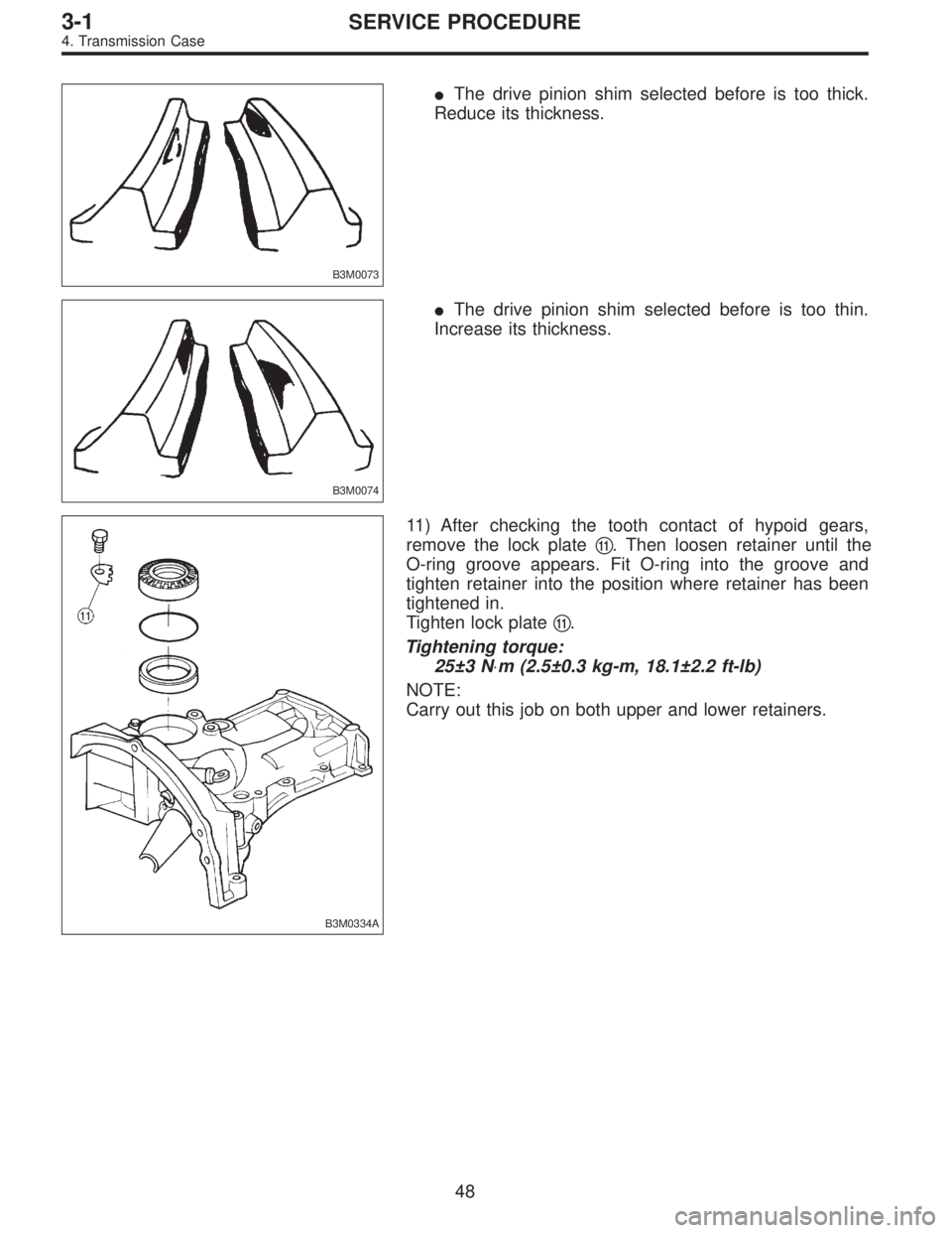
B3M0073
�The drive pinion shim selected before is too thick.
Reduce its thickness.
B3M0074
�The drive pinion shim selected before is too thin.
Increase its thickness.
B3M0334A
11) After checking the tooth contact of hypoid gears,
remove the lock plate�
11. Then loosen retainer until the
O-ring groove appears. Fit O-ring into the groove and
tighten retainer into the position where retainer has been
tightened in.
Tighten lock plate�
11.
Tightening torque:
25±3 N⋅m (2.5±0.3 kg-m, 18.1±2.2 ft-lb)
NOTE:
Carry out this job on both upper and lower retainers.
48
3-1SERVICE PROCEDURE
4. Transmission Case
Page 324 of 2248
G3M0573
12) Selecting of main shaft rear plate
Using ST, measure the amount A of ball bearing protrusion
from transmission main case surface and select the proper
plate in the following table:
ST 498147000 DEPTH GAUGE
Dimension“A”
mm (in)Part No. Mark
4.00—4.13
(0.1575—0.1626)32294AA040 1
3.87—3.99
(0.1524—0.1571)32294AA050 2
NOTE:
Before measuring, tap the end of main shaft with a plastic
hammer lightly in order to make the clearance zero
between the main case surface and the moving flange of
bearing.
B3M0336A
13) Install clutch release lever�1and bearing�2.
49
3-1SERVICE PROCEDURE
4. Transmission Case
Page 335 of 2248
 Put vinyl tape around main shaft splines to protect oil
seal from damage. Then pull out oil seal and needle bear-
ing by hand.
2) Remove lock nut from")
B3M0087A
7. Main Shaft Assembly
A: DISASSEMBLY
1) Put vinyl tape around main shaft splines to protect oil
seal from damage. Then pull out oil seal and needle bear-
ing by hand.
2) Remove lock nut from transmission main shaft assem-
bly.
NOTE:
Remove caulking before taking off lock nut.
ST1 498937000 TRANSMISSION HOLDER
ST2 499987003 SOCKET WRENCH (35)
G3M0644
3) Remove insert stopper plate�1, sleeve and hub assem-
bly No. 2, baulk ring�
3, 5th drive gear�4, and needle
bearing�
5(32 x 36 x 25.7).
G3M0645
4) Using ST1, ST2 and a press, remove:
�5th needle bearing inner race�
1
�5th gear thrust washer�2
�Ball bearing�3(25.5 x 65 x 31)
�4th gear thrust washer�
4
�4th drive gear�5
�Sleeve and hub assembly�6
�Baulk ring�7
�4th needle bearing�8
�4th needle bearing inner race�9
�3rd drive gear�10
ST1 899864100 REMOVER
ST2 899714110 REMOVER
NOTE:
Replace sleeve and hub with new ones. Do not attempt to
disassemble because they must engage at a specified
point. If they should be disassembled, mark engagement
point on splines beforehand.
60
3-1SERVICE PROCEDURE
7. Main Shaft Assembly
 Selecting of main shaft rear plate
Using ST, measure the amount A of ball bearing protrusion
from transmission main case surface and select the proper
plate in the following table:
ST 4981")