Page 374 of 2248
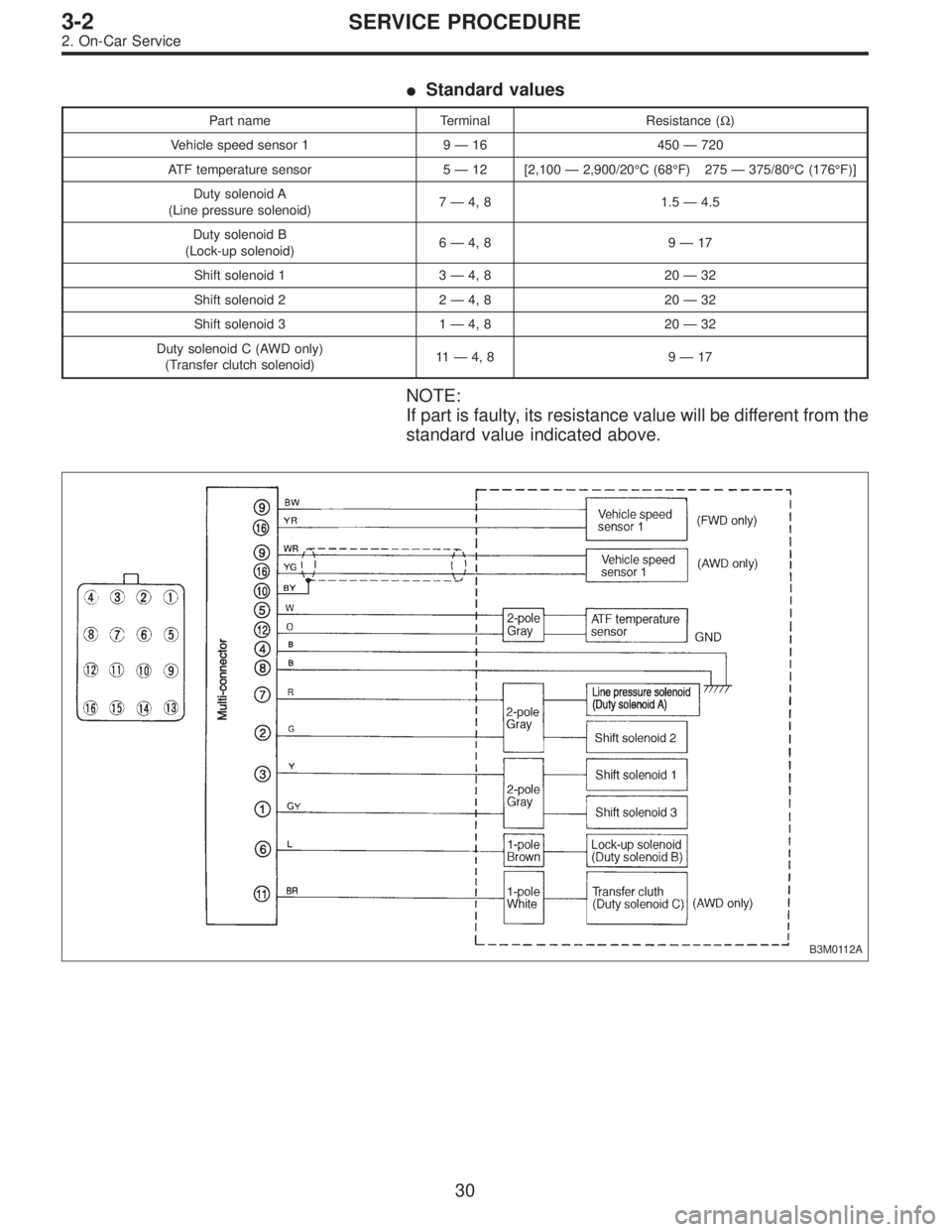
�Standard values
Part name Terminal Resistance (Ω)
Vehicle speed sensor 1 9—16 450—720
ATF temperature sensor 5—12 [2,100—2,900/20°C (68°F) 275—375/80°C (176°F)]
Duty solenoid A
(Line pressure solenoid)7—4, 8 1.5—4.5
Duty solenoid B
(Lock-up solenoid)6—4, 8 9—17
Shift solenoid 1 3—4, 8 20—32
Shift solenoid 2 2—4, 8 20—32
Shift solenoid 3 1—4, 8 20—32
Duty solenoid C (AWD only)
(Transfer clutch solenoid)11—4, 8 9—17
NOTE:
If part is faulty, its resistance value will be different from the
standard value indicated above.
B3M0112A
30
3-2SERVICE PROCEDURE
2. On-Car Service
Page 375 of 2248
G3M0297
C: REMOVAL AND INSTALLATION
1. SHIFT SOLENOID, DUTY SOLENOID AND VALVE
BODY
1) Removal
(1) Clean transmission exterior.
(2) Drain ATF completely.
NOTE:
Tighten ATF drain plug after draining ATF.
Tightening torque:
25±2 N⋅m (2.5±0.2 kg-m, 18.1±1.4 ft-lb)
G3M0861
(3) Remove oil pan and gasket.
NOTE:
Drain oil into a container.
(4) Disconnect solenoid valve connectors.
Remove connectors from clips and disconnect connec-
tors at 4 places.
G3M0862
(5) Remove oil strainer.
Disconnect oil pipe by removing the two bolts, and
remove four bolts and oil strainer.
NOTE:
Be careful because oil flows from oil strainer.
31
3-2SERVICE PROCEDURE
2. On-Car Service
Page 378 of 2248
G3M0304
2. DUTY SOLENOID C AND TRANSFER VALVE BODY
1) Removal
(1) Remove pitching stopper.
G3M0297
(2) Raise vehicle and drain ATF.
G3M0305
(3) Remove front exhaust pipe.
Disconnect oxygen sensor connector, and remove
exhaust pipe.
G3M0782
(4) Remove propeller shaft.
NOTE:
Before removing propeller shaft, scribe matching marks on
propeller shaft and rear differential coupling.
G3M0306
(5) Remove rear crossmember.
�Support transmission using a transmission jack and
raise slightly.
�Remove bolts and nuts as shown in Figure.
34
3-2SERVICE PROCEDURE
2. On-Car Service
Page 379 of 2248
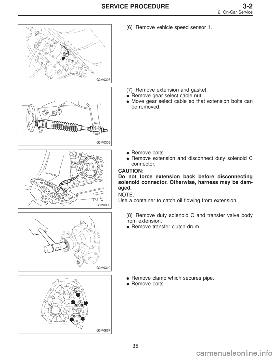
G3M0307
(6) Remove vehicle speed sensor 1.
G3M0308
(7) Remove extension and gasket.
�Remove gear select cable nut.
�Move gear select cable so that extension bolts can
be removed.
G3M0309
�Remove bolts.
�Remove extension and disconnect duty solenoid C
connector.
CAUTION:
Do not force extension back before disconnecting
solenoid connector. Otherwise, harness may be dam-
aged.
NOTE:
Use a container to catch oil flowing from extension.
G3M0310
(8) Remove duty solenoid C and transfer valve body
from extension.
�Remove transfer clutch drum.
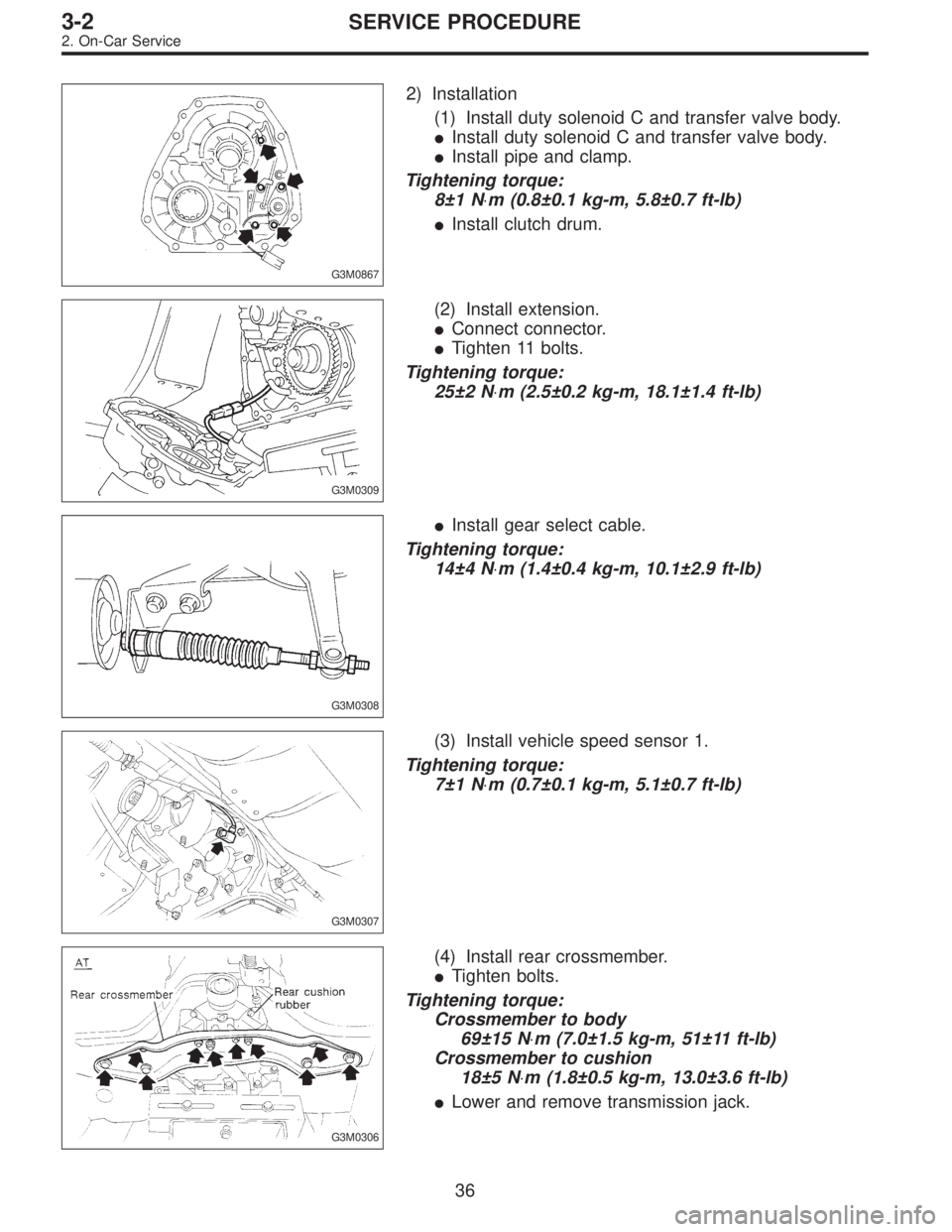
G3M0867
�Remove clamp which secures pipe.
�Remove bolts.
35
3-2SERVICE PROCEDURE
2. On-Car Service
Page 380 of 2248
G3M0867
2) Installation
(1) Install duty solenoid C and transfer valve body.
�Install duty solenoid C and transfer valve body.
�Install pipe and clamp.
Tightening torque:
8±1 N⋅m (0.8±0.1 kg-m, 5.8±0.7 ft-lb)
�Install clutch drum.
G3M0309
(2) Install extension.
�Connect connector.
�Tighten 11 bolts.
Tightening torque:
25±2 N⋅m (2.5±0.2 kg-m, 18.1±1.4 ft-lb)
G3M0308
�Install gear select cable.
Tightening torque:
14±4 N⋅m (1.4±0.4 kg-m, 10.1±2.9 ft-lb)
G3M0307
(3) Install vehicle speed sensor 1.
Tightening torque:
7±1 N⋅m (0.7±0.1 kg-m, 5.1±0.7 ft-lb)
G3M0306
(4) Install rear crossmember.
�Tighten bolts.
Tightening torque:
Crossmember to body
69±15 N⋅m (7.0±1.5 kg-m, 51±11 ft-lb)
Crossmember to cushion
18±5 N⋅m (1.8±0.5 kg-m, 13.0±3.6 ft-lb)
�Lower and remove transmission jack.
36
3-2SERVICE PROCEDURE
2. On-Car Service
Page 382 of 2248

3. Performance Test
A: STALL TEST
1. GENERAL
The stall test is of extreme importance in diagnosing the
condition of the automatic transmission and the engine. It
should be conducted to measure the engine stall speeds in
all shift ranges except the P and N ranges.
Purposes of the stall test:
1) To check the operation of the automatic transmission
clutch.
2) To check the operation of the torque converter clutch.
3) To check engine performance.
2. TEST METHODS
Preparations before test:
�
1Check that throttle valve opens fully.
�
2Check that engine oil level is correct.
�
3Check that coolant level is correct.
�
4Check that ATF level is correct.
�
5Check that differential gear oil level is correct.
�
6Increase ATF temperature to 60 to 80°C (140 to 176°F)
by idling the engine for approximately 30 minutes (with
select lever set to“N”or“P”).
1) Install an engine tachometer at a location visible from
the driver’s compartment and mark the stall speed range
on the tachometer scale.
2) Place the wheel chocks at the front and rear of all
wheels and engage the parking brake.
3) Move the manual linkage to ensure it operates properly,
and shift the select lever to the 2 range.
B3M0286B
4) While forcibly depressing the foot brake pedal, gradu-
ally depress the accelerator pedal until the engine operates
at full throttle.
38
3-2SERVICE PROCEDURE
3. Performance Test
Page 383 of 2248
 When the engine speed is stabilized, read that speed
quickly and release the accelerator pedal.
6) Shift the select lever to Neutral, and cool down the
engine by idling it for more than one minute.")
5) When the engine speed is stabilized, read that speed
quickly and release the accelerator pedal.
6) Shift the select lever to Neutral, and cool down the
engine by idling it for more than one minute.
7) Record the stall speed.
8) If stall speed in 2 range is higher than specifications,
forward clutch slipping on brake band slipping may occur.
To identify it, conduct the same test as above in D range.
9) Perform the stall tests with the select lever in the R
range.
CAUTION:
�Do not continue the stall test for MORE THAN FIVE
SECONDS at a time (from closed throttle, fully open
throttle to stall speed reading). Failure to follow this
instruction causes the engine oil and ATF to deterio-
rate and the clutch and brake band to be adversely
affected.
Be sure to cool down the engine for at least one minute
after each stall test with the select lever set in the P or
N range and with the idle speed lower than 1,200 rpm.
�If the stall speed is higher than the specified range,
attempt to finish the stall test in as short a time as
possible, in order to prevent the automatic transmis-
sion from sustaining damage.
Specifications
Stall speed (at sea level):
2200 cc 2,300 — 2,700 rpm
3. EVALUATION
Stall speed
(at sea level)Position Cause
Less than specifications2
R�Throttle valve not fully open
�Erroneous engine operation
�Torque converter clutch’s one-way clutch slipping
Greater than specificationsD�Forward clutch slipping
�One-way clutch (1-2) malfunctioning
R�Line pressure too low
�Reverse clutch slipping
�Low & reverse brake slipping
2�Line pressure too low
�Forward clutch slipping
�Brake band slipping
�One-way clutch (3-4) malfunctioning
39
3-2SERVICE PROCEDURE
3. Performance Test
Page 387 of 2248

G3M0870
D: TRANSFER CLUTCH PRESSURE TEST
Check transfer clutch pressure in accordance with the fol-
lowing chart in the same manner as with line pressure.
ST 499897700 OIL PRESSURE ADAPTER SET
ST 498575400 OIL PRESSURE GAUGE ASSY
AWD mode:“D”range
FWD mode:“P”range, engine speed 2000 rpm
CAUTION:
Before setting in FWD mode, install spare fuse on FWD
mode switch.
Unit: kPa (kg/cm2, psi)
Duty ratio
(%)AWD mode FWD mode
5667—804
(6.8—8.2, 97—117)667—804
(6.8—8.2, 97—117)
40137—226
(1.4—2.3, 20—33)—
950
(0, 0)—
If oil pressure is not produced or if it does not change in the
AWD mode, the duty solenoid C or transfer valve assem-
bly may be malfunctioning. If oil pressure is produced in the
FWD mode, the problem is similar to that in the AWD
mode.
E: ROAD TEST
1. GENERAL
Road tests should be conducted to properly diagnose the
condition of the automatic transmission.
CAUTION:
When performing test, do not exceed posted speed
limit.
2. CHECKING FOR SHIFT PATTERNS
Check“kick-down”.
D range: 1st
←
→2nd←
→3rd←
→4th
3 range: 1st←
→2nd←
→3rd←4th
2 range: 2nd←3rd←4th
1 range: 1st←2nd←3rd←4th
3. CHECK FOR ENGINE BRAKE OPERATION
Engine brake operation:
D range→4th gear
3 range→3rd gear
2 range→2nd gear
1 range→1st gear
43
3-2SERVICE PROCEDURE
3. Performance Test
 Removal
(1) Clean transmission exterior.
(2) Drain ATF completely.
NOTE:
Tighten ATF drain plug after draining AT")
 Removal
(1) Remove pitching stopper.
G3M0297
(2) Raise vehicle and drain ATF.
G3M0305
(3) Remove front exhaust pipe.
Disconnect oxygen sensor conn")