Page 1422 of 1701

TROUBLEDIAGNOSES
Preliminary Check
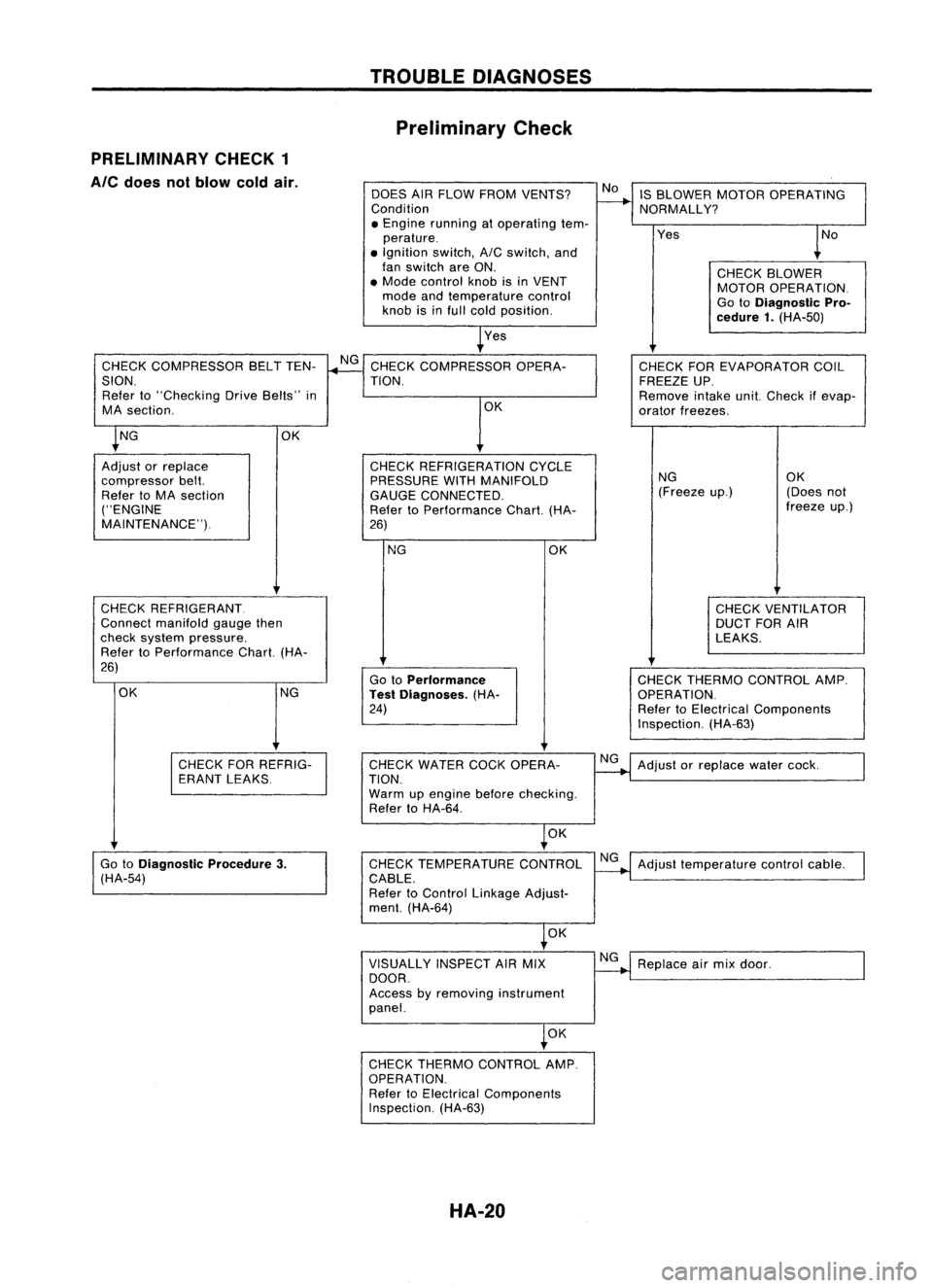
PRELIMINARY CHECK1
Ale
does notblow coldair.
DOESAIRFLOW FROM VENTS?
Condition
• Engine running atoperating tem-
perature .
• Ignition switch,AICswitch, and
fan switch areON.
• Mode control knobisin VENT
mode andtemperature control
knob isinfull cold position.
Yes IS
BLOWER MOTOROPERATING
NORMALLY?
Yes
CHECKBLOWER
MOTOR OPERATION.
Go toDiagnostic Pro-
cedure 1.(HA-50)
CHECK COMPRESSOR BELTTEN-
SION. Refer to"Checking DriveBelts" in
MA section.
CHECK REFRIGERANT.
Connect manifold gaugethen
check system pressure.
Refer toPerformance Chart.(HA-
26)
NG CHECK
THERMO CONTROL AMP.
OPERATION.
Refer toElectrical Components
Inspection. (HA-63)
CHECK
FOREVAPORATOR COIL
FREEZE UP.
Remove intakeunit.Check ifevap-
orator freezes.
NG OK
(Freeze up.) (Doesnot
freeze up.)
CHECK VENTILATOR
DUCT FORAIR
LEAKS.
OK
Go toPerformance
Test Diagnoses. (HA-
24)
NG
CHECK
REFRIGERATION CYCLE
PRESSURE WITHMANIFOLD
GAUGE CONNECTED.
Refer toPerformance Chart.(HA-
26) OK
CHECK
COMPRESSOR OPERA-
TION.
OK
OK NG
Adjust orreplace
compressor belt.
Refer toMA section
("ENGINE
MAINTENANCE").
CHECKFORREFRIG-
ERANT LEAKS CHECK
WATER COCKOPERA-
TION.
Warm upengine beforechecking.
Refer toHA-64.
NG
Adjust orreplace watercock.
OK
Go toDiagnostic Procedure3.
(HA-54) CHECK
TEMPERATURE CONTROL
CABLE.
Refer toControl Linkage Adjust-
ment. (HA-64) NG
Adjust temperature controlcable.
OK
VISUALLY INSPECTAIRMIX
DOOR.
Access byremoving instrument
panel. NG
Replace airmix door.
OK
CHECK THERMO CONTROL AMP.
OPERATION. Refer toElectrical Components
Inspection. (HA-63)
HA-20
Page 1423 of 1701
PRELIMINARY CHECK2
Air outlet doesnotchange. TROUBLE
DIAGNOSES
Preliminary Check(Cont'd)
TURN IGNITION SWITCHANDFANSWITCH ON.DOES AIR No
Adjustmodecontrol cable.Referto
COME OUTNORMALLY FROMEACHDUCTWHEN EACH HA-64.
MODE SWITCH ISPUSHED?
Discharge airflow
Switch Airoutlet/distribution
model RHOmodels
LHDmodels
indicator FaceFoot
Defroster FaceFoot
Defroster
iI
100%
-
-
100%
-
-
.
,7,./
60%40%
-
60%40%
-
,~
-
80%
20%14%65% 21%
,~
-
60% 40%
13%57% 30%
\tEl
-
-
100%
-
-
100%
res
INSPECTION END
HA-21
•
Page 1425 of 1701

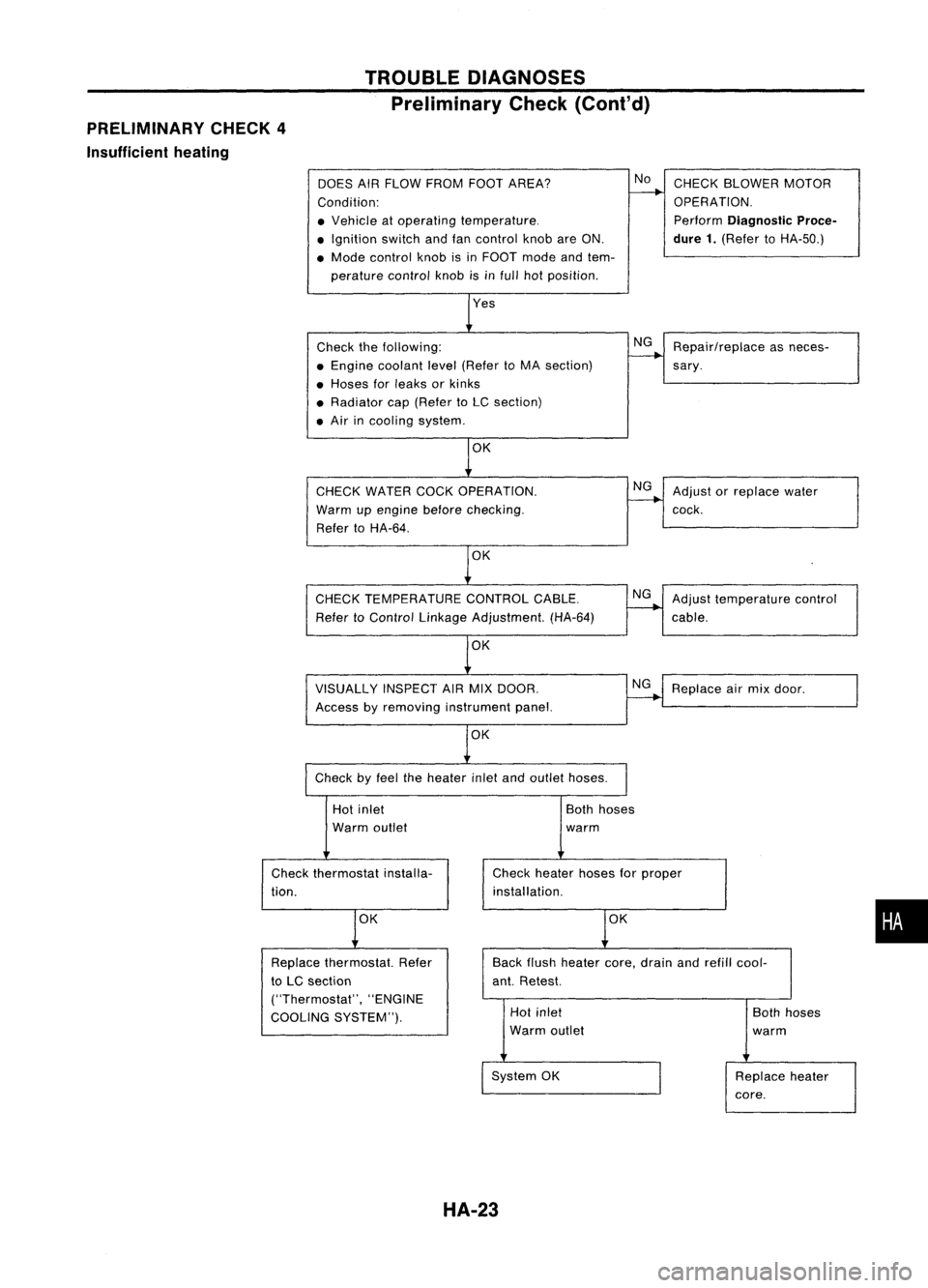
PRELIMINARY CHECK4
Insufficient heating TROUBLE
DIAGNOSES
Preliminary Check(Cont'd)
DOES AIRFLOW FROM FOOTAREA?
Condition:
• Vehicle atoperating temperature .
• Ignition switchandfancontrol knobareON.
• Mode control knobisin FOOT modeandtem-
perature controlknobisinfull hotposition.
Check thefollowing:
• Engine coolant level(Refer toMA section)
• Hoses forleaks orkinks
• Radiator cap(Refer toLC section)
• Air incooling system.
CHECK WATER COCKOPERATION.
Warm upengine before
checking.
Refer toHA-64.
OK
CHECK TEMPERATURE CONTROLCABLE.
Refer toControl Linkage Adjustment. (HA-64)
VISUALLY INSPECTAIRMIX DOOR.
Access byremoving instrument panel.
OK
Check byfeel theheater inletandoutlet hoses.
No
NG
NG
NG
NG
CHECK
BLOWER MOTOR
OPERATION.
Perform
Diagnostic Proce-
dure 1.
(Refer toHA-50.)
Repair/replace asneces-
sary .
Adjust orreplace water
cock.
Adjust temperature control
cable.
Replace airmix door.
Hot inlet
Warm outlet
Check thermostat installa-
tion.
OK
Both
hoses
warm
Check heater hosesforproper
installation.
OK
•
Back
flush heater core,drain andrefill cool-
ant. Retest.
Replace
thermostat. Refer
to LC section
("Thermostat", "ENGINE
COOLING SYSTEM"). Hot
inlet
Warm outlet
System OK
HA-23
Both
hoses
warm
Replace heater
core.
Page 1439 of 1701
TROUBLEDIAGNOSES
Wiring Diagram -HEATER -(Conl'd)
r-------------------,
1~ ~~)1
: (b)
@ :
L ~
•
Refer
tolast page
(Fo'ldout page).
HA-HEATER-02
(b):
LHDmodels
@:
RHOmodels
@: ForEurope andIsrae 1
@:
Except@
*1
(6)
GIS
ViS
*2
<0
G/Y,
@
Y/R
,
RECIRCULATION
SWITCH
~
Refer
toEL-POWER.
LG/R
ffi
INDICATOR
INTAKE
DOOR
MOTOR
~
L
FUSE
BLOCK
(JIB)
~
IN21
•
LG/R
7.5A
III
~B
I
~O
IGNITION
SWITCH
ON
EE
~~
~W
Preceding
~B
page ~
HHA013
HA-37
Page 1440 of 1701
TROUBLEDIAGNOSES
Wiring Diagram -
Ale -
HA-A/C-01
B
f>
Next page
B
.JC'-.-
ToHA-A/C
~-06
FAN
SWITCH
~
ILL.
@
-
r
*1~TO HA-A/C-03
.. RIG ~
ToEL-ILL
*1 RIG
12-51
n=tn
Refer
toEL-POWER.
Q:
LHOmodels
RHOmodels
@:
ForEurope andIsrael
@:
Except@
t
LIB
@:
CDengine RHOmodels
~~~~::OR
-(0
Gty·
@
LGtS
~
., __ LI~I_;~f
t
L/W
L/Y
LlR
LIB
12-4 1
12-31 12~
I
Ii2'ilI
FUSE
15A BLOCK
m
(JIB)
~
IGNITION
SWITCH
ON
IGNITION SWITCH
ACe
or
ON
~lbi=ll
B B
rro::::::-.--::::;8::--
L
--o::::
1 __...
1
JOINT
B CONNECTOR-4
~1
~:
~ {}B.---
IW'ia\ ~ ~
fiI-B
=~
\~ ~I \~ ~~I ~
Q
15A
IT]
I
N3
1 -
L/W
L/W
L.l
I
L/W
~1
BLOWER
M
MOTOR
(fill)
I!:j:lI
LIB
r--------------------,
I ~I
I
0
I
1~@1~1
I~W 2Wi
I I
I I
~--------------------~
m:ITillIillIill
@
~P
Refer
tolast page
(Foldout page).
~
HHA002
HA-38
Page 1449 of 1701
TROUBLEDIAGNOSES
Wiring Diagram -
Ale -
(Cont'd)
SR20DE engineAITmodels
HA-A/C-10
IGNITION SWITCH
ON orSTART
•
t
t
Refer tolast page
(Foldout page).
CHID
(El01)
,
(lliID
(IT)
t
t
-
COOLING
FAN
MOTOR-2
~
I
I
BR G/WLG/R
CDDLINGI:i:1 :lJ1
I~II
FAN
nn
RELAY-3
UU
~ I!:i=!IIl:i=lI
n,;JJ
LG
G/OR
B
1--&
Refer
toEL-POWER.
Hi
(-)
lLjJJ
LG/R B
___ I-_!,
rl.
B B
-!- -!-
~
~ m,(ffi)
\MJ GYGY
ECM
(ECCS
CONTROL
MODULE)
(ED
10A
FUSE
~.j;l
125
I
~J9~~
30A30A
(El06)
IT]
[B]
GY
G/W
I I
----,-I-F.~=
BRGY
G/W
BRGYLG/B
COOlING(!IIZ
I~II
CODLING11!1 ]II~II
~~~AY-1 .~ ~~~~AY-2 ~~
m> ~
Il:i=lI
4=Jl
@
I!:i=!IIl:i=lI
4=ll
LG/R
G/BG/R
LG
G/Y
B
r:r -
~r=!-JI
1-
I$~ --- ~$I
G/B G/R
LG
CHID
LG/R
m m
I I
[+)
COOLING
[+)
FAN
LG ~LG/R MOTOR-1
1c!J~
-F~:
~c!J1
Lo
rn
LG
CEID
LG/R
I
J
I
f
LG LG/R
~ m
RFRH RFRL
~ m>,,(E18)
IIDm
BRBRBR
HHA010
HA-47
Page 1450 of 1701
TROUBLEDIAGNOSES
Wiring Diagram -
A/C -
(Cont'd)
CD20 engine models
HA-A/C-11
IGNITION SWITCH
ON or START
:
LHDmode 1s
@:
RHDmodels
tt
I
I
BR G/WLG/R
COOLING1:}:1
:!J'
I~II
FAN
nn
RELAY-3
UU
((@
I'=idI
IliJI~
LG G/OR B
1--1
FUSE
r1!Jj;1]
RefertoEL-POWER.
10A BLOCK 30A30A
1251
(J/B)
(Et06)
0
[B]
GY G/W
1---1
_ ....-,-I-F.
,-1=
BR GYG/W BRGYLG/B
COOLING1:Jt1 1::11
I~II
COOLING
1
:!: ::JI
::II
FAN
nn
FAN
nn
RELAY-1
UU
RELAY-2
UU
llli>
I'=idI
IliJI ~ ~
I'=idI
Iki=ll~
LG/R G/BG/R LGG/Y B
~ 1-1_
I..J
1_
r~-CJI::~.
971~
G/BG/YCOOLING
<;::J:=;> ~
dbdbFAN
LG Ifii\i\LG/R LGIfii\i\LG/R II111 II2 II MOTOR-1
,..,Ib ~ ~
r::::!=~ r::::!=
LaHi
IE"4S
~-M-a-~ "1rlt-M-a-iI3.r1l (+)(+)~
LG
CHID
LG/R LG
CHID
LG/R
M
~£:r
HiHi
O~I.
R
ijl ijl
I
0
LG/BB LG/RB
tt
LG
t
L:/R
t
LI
L...I
r'
IFffill
m
ECM _,
1.____...,
R/FAN2 R/FAN1 (ENGINE
CONTROL BB
MODULE)
-!--!-
@
~ llli>,@,((@
~BR BRBR
~@,~
~ GYGY
Refer
tolast page
(Foldout page).
CHID
(EiOt)
,
~
HHA011
HA-48
Page 1451 of 1701
TROUBLEDIAGNOSES
Main Power Supply andGround CircuitCheck
POWER SUPPLY CIRCUIT CHECKFORAICSYSTEM
Check powersupply circuitforairconditioning system.
Refer to"POWER SUPPLYROUTING" inEL section andWiring
Diagram.
Voltmeterterminal
THERMO
CONTROL AMP.CHECK
Check powersupply circuitforthermo controlamp.withignition
switch ON.
1~ Disconnect thermocontrolamp.harness connector.
2. Connect voltmeter fromharness side.
3. Measure voltageacrossterminal No.
CD
and body ground.
Ohmmeter terminal
Turn
AIC
andfanswitches ON.Check bodyground circuitfor
thermo controlamp.
1. Disconnect thermocontrolamp.harness connector.
2. Connect ohmmeter fromharness side.
3. Check forcontinuity betweenterminalNo.@and body
ground.
~I()~
Thermo controlamp.
connector@
Lom ~
RHA341F
~Iv~
Thermo controlamp.
connector
@
;
~~.
LHD 2 \... ~
models:
GIS
Uw-i
RHD [][]
models: GY
Continuity exists:OK
'="RHA342F
EB
CD
EB
@
HA-49
e
Body ground
e
Body ground Voltage
Approx. 12V
Continuity
Yes
•