1995 NISSAN ALMERA N15 ignition
[x] Cancel search: ignitionPage 1371 of 1701
HOWTOREAD WIRING DIAGRAMS
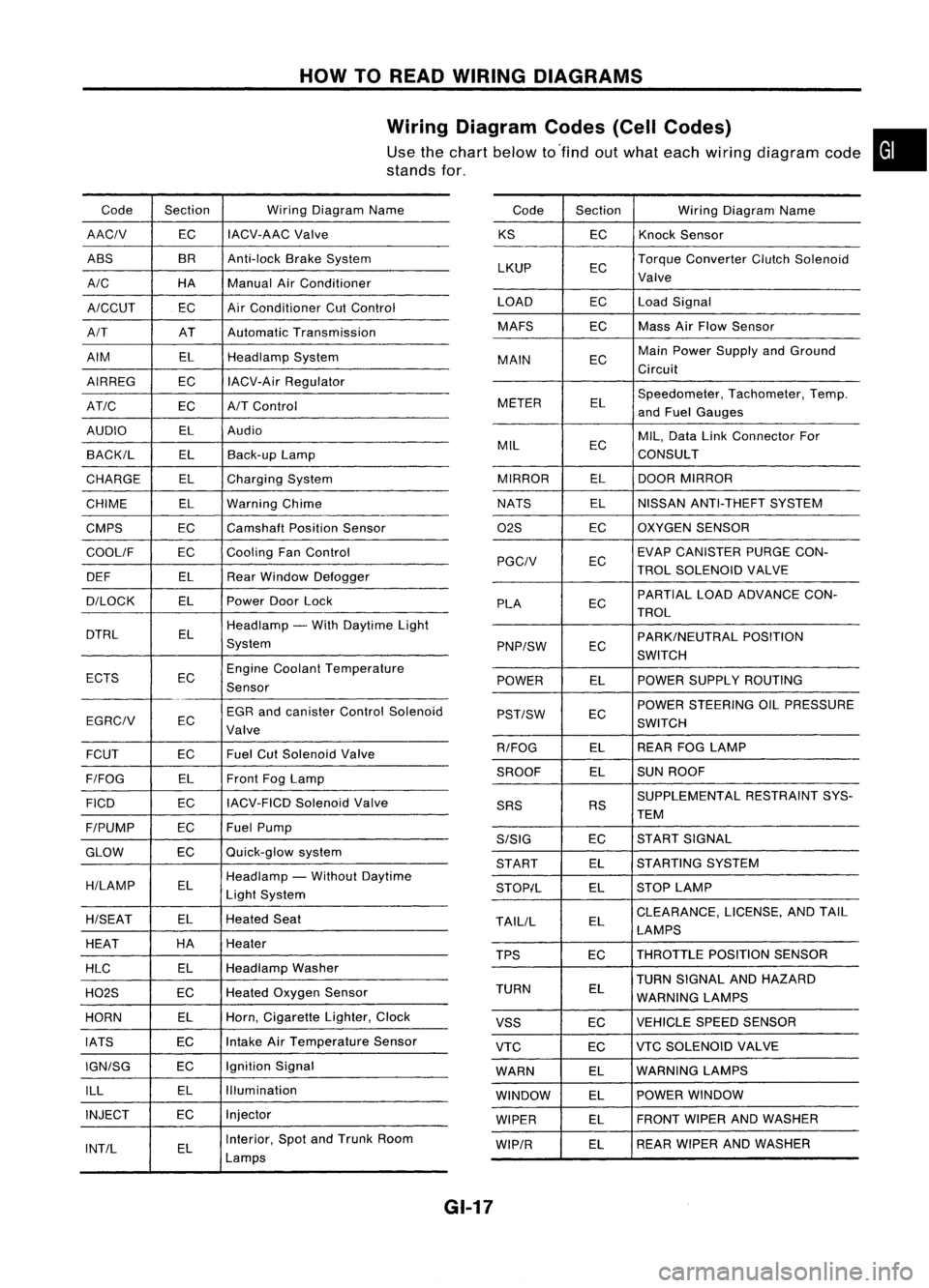
Wiring Diagram Codes(CellCodes)
Use thechart below to'find outwhat each wiring diagram code•
stands for,
Code Section WiringDiagram Name
AACIV ECIACV-AAC
Valve
ABS BR
Anti-lock BrakeSystem
A/C HAManualAirConditioner
A/CCUT ECAir
Conditioner CutControl
A/T ATAutomatic Transmission
AIM ELHeadlamp System
AIRREG ECIACV-Air Regulator
AT/C ECA/TControl
AUDIO ELAudio
BACK/L ELBack-up Lamp
CHARGE ELCharging System
CHIME ELWarning Chime
CMPS EC
Camshaft PositionSensor
COOllF ECCooling
FanControl
DEF ELRearWindow Defogger
D/LOCK ELPowerDoorLock
DTRL ELHeadlamp
-With Daytime Light
System
ECTS ECEngine
Coolant Temperature
Sensor
EGR andcanister ControlSolenoid
EGRCIV EC
Valve
FCUT ECFuel
CutSolenoid Valve
F/FOG ELFront
FogLamp
FICO ECIACV-FICD
SolenoidValve
F/PUMP ECFuel
Pump
GLOW ECQuick-glow
system
H/LAMP ELHeadlamp
-Without Daytime
Light System
H/SEAT ELHeated
Seat
HEAT HA
Heater
HLC ELHeadlamp
Washer
H02S ECHeated
Oxygen Sensor
HORN ELHorn,
Cigarette Lighter,Clock
IATS ECIntake
AirTemperature Sensor
IGN/SG ECIgnition
Signal
ILL ELIllumination
INJECT ECInjector
INT/L ELInterior,
SpotandTrunk Room
Lamps Code
Section WiringDiagram Name
KS ECKnock
Sensor
LKUP ECTorque
Converter ClutchSolenoid
Valve
LOAD ECLoadSignal
MAFS ECMass
AirFlow Sensor
MAIN ECMain
Power Supply andGround
Circuit
METER ELSpeedometer,
Tachometer,Temp.
and Fuel Gauges
MIL ECMIL,
Data LinkConnector For
CONSULT
MIRROR ELDOOR
MIRROR
NATS ELNISSAN
ANTI-THEFT SYSTEM
02S ECOXYGEN
SENSOR
EC EVAP
CANISTER PURGECON-
PGCIV TROLSOLENOID VALVE
PLA ECPARTIAL
LOADADVANCE CON-
TROL
EC PARK/NEUTRAL
POSITION
PNP/SW SWITCH
POWER ELPOWER
SUPPLY ROUTING
POWER STEERING OILPRESSURE
PST/SW EC
SWITCH
R/FOG ELREAR
FOGLAMP
SROOF ELSUN
ROOF
SUPPLEMENTAL RESTRAINTSYS-
SRS RS
TEM
S/SIG ECST
ART SIGNAL
START ELSTARTING
SYSTEM
STOP/L ELSTOP
LAMP
TAllIL ELCLEARANCE,
LICENSE,ANDTAIL
LAMPS
TPS ECTHROTTLE
POSITIONSENSOR
TURN SIGNAL ANDHAZARD
TURN EL
WARNING LAMPS
VSS ECVEHICLE
SPEEDSENSOR
VTC ECVTC
SOLENOID VALVE
WARN ELWARNING
LAMPS
WINDOW ELPOWER
WINDOW
WIPER ELFRONT
WIPERANDWASHER
WIP/R ELREAR
WIPER ANDWASHER
GI-17
Page 1379 of 1701
HOWTOPERFORM EFFICIENT DIAGNOSIS FORANELECTRICAL INCIDENT
Circuit Inspection (Cont'd)
Voltage checkmethod
1. Remove theblown fuseanddisconnect allloads (i.e.SW1 open, relaydisconnected andsolenoid •
disconnected) poweredthroughthefuse.
2. Turn theignition keytothe ONorSTART position. Verifybattery voltage atthe B
+
side ofthe fuse
terminal (oneleadonthe B
+
terminal sideofthe fuse block andone lead onaknown goodground).
3. With SW1 open andtheDMM leads across bothfuseterminals, checkforvoltage.
voltage; shortisbetween fuseblock andSW1 (point A).
no voltage; shortisfurther downthecircuit thanSW1.
4. With SW1 closed, relayandsolenoid disconnected andtheDMM leadsacross bothfuseterminals,
check forvoltage.
voltage; shortisbetween SW1andtherelay (point B).
no voltage; shortisfurther downthecircuit thantherelay.
5. With SW1 closed, relaycontacts jumpedwithfused jumper wirecheck forvoltage.
voltage; shortisdown thecircuit ofthe relay orbetween therelay andthedisconnected sole-
noid (point C).
no voltage; retracestepsandcheck power tofuse block.
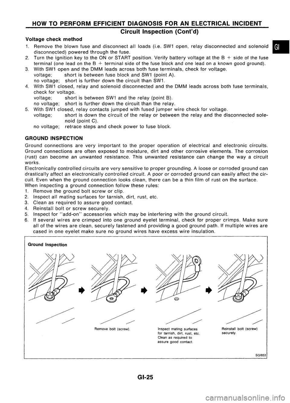
GROUND INSPECTION
Ground connections arevery important tothe proper operation ofelectrical andelectronic circuits.
Ground connections areoften exposed tomoisture, dirtand other corrosive elements. Thecorrosion
(rust) canbecome anunwanted resistance. Thisunwanted resistance canchange theway acircuit
works. Electronically controlledcircuitsarevery sensitive toproper grounding. Aloose orcorroded groundcan
drastically affectanelectronically controlledcircuit.Apoor orcorroded groundcaneasily affectthecir-
cuit. Even when theground connection looksclean, therecanbeathin film ofrust onthe surface.
When inspecting aground connection followtheserules:
1. Remove theground boltscrew orclip.
2. Inspect allmating surfaces fortarnish, dirt,rust, etc.
3. Clean asrequired toassure goodcontact.
4. Reinstall boltorscrew securely.
5. Inspect for"add-on" accessories whichmaybeinterfering withtheground circuit.
6. Ifseveral wiresarecrimped intoone ground eyeletterminal, checkforproper crimps. Makesure
all ofthe wires areclean, securely fastened andproviding agood ground path.Ifmultiple wiresare
cased inone eyelet makesurenoground wireshaveexcess wireinsulation.
Ground Inspection
•
Removeboll(screw).
•
GI-25
Inspect
matingsurfaces
for tarnish. dirt.rust. etc.
Clean asrequired to
assure goodcontact.
•
Reinstallbolt(screw)
securely.
SGI853
Page 1383 of 1701
HOWTOFOLLOW FLOWCHART INTROUBLE DIAGNOSES
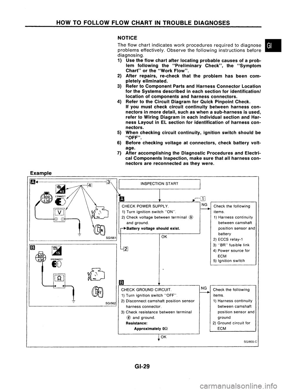
NOTICE
The flow chart indicates workprocedures requiredtodiagnose
problems effectively. Observethefollowing instructions before
diagnosing.
1) Use theflow chart afterlocating probable causesofaprob-
lem following the"Preliminary Check",the"Symptom
Chart" orthe "Work Flow".
2) After repairs, re-check thattheproblem hasbeen com-
pletely eliminated.
3) Refer toComponent PartsandHarness Connector Location
for the Systems described ineach section foridentificationl
location ofcomponents andharness connectors.
4) Refer tothe Circuit Diagram forQuick Pinpoint Check.
If you must check circuit continuity betweenharnesscon-
nectors inmore detail, suchaswhen asub-harness isused,
refer toWiring Diagram ineach individual sectionandHar-
ness Layout inEL section foridentification ofharness con-
nectors.
5) When checking circuitcontinuity, ignitionswitchshould be
"OFF" .
6) Before checking voltageatconnectors, checkbattery volt-
age.
7) After accomplishing theDiagnostic Procedures andElectri-
cal Components Inspection,makesurethatallharness con-
nectors arereconnected asthey were.
•
Example
m ..
-=-=~-----------~
~
~i5
[YJ
SGI561
~
OISCONNECT
18
SGI562
INSPECTION
START
CHECK POWER SUPPLY.
1) Turn ignition switch"ON".
2) Check voltage between terminal
@
and ground.
~Ba"ery voltageshouldexist.
OK
2
Ii)
CHECK GROUND CIRCUIT.
1) Turn ignition switch"OFF"
2) Disconnect camshaftpositionsensor
harness connector.
3) Check resistance betweenterminal
@
and ground.
Resistance: Approximately
on
OK
GI-29 NG
Check
thefollowing
items. 1) Harness continuity
between camshaft
position sensorand
battery
2) ECCS relay-1
3) "SR" fusible link
4) Power source for
ECM
5) Ignition switch
Check thefollowing
items. 1) Harness continuity
between camshaft
position sensorand
ground
2) Ground circuitfor
ECM
SG1800-C
Page 1384 of 1701
HOWTOFOLLOW FLOWCHART INTROUBLE DIAGNOSES
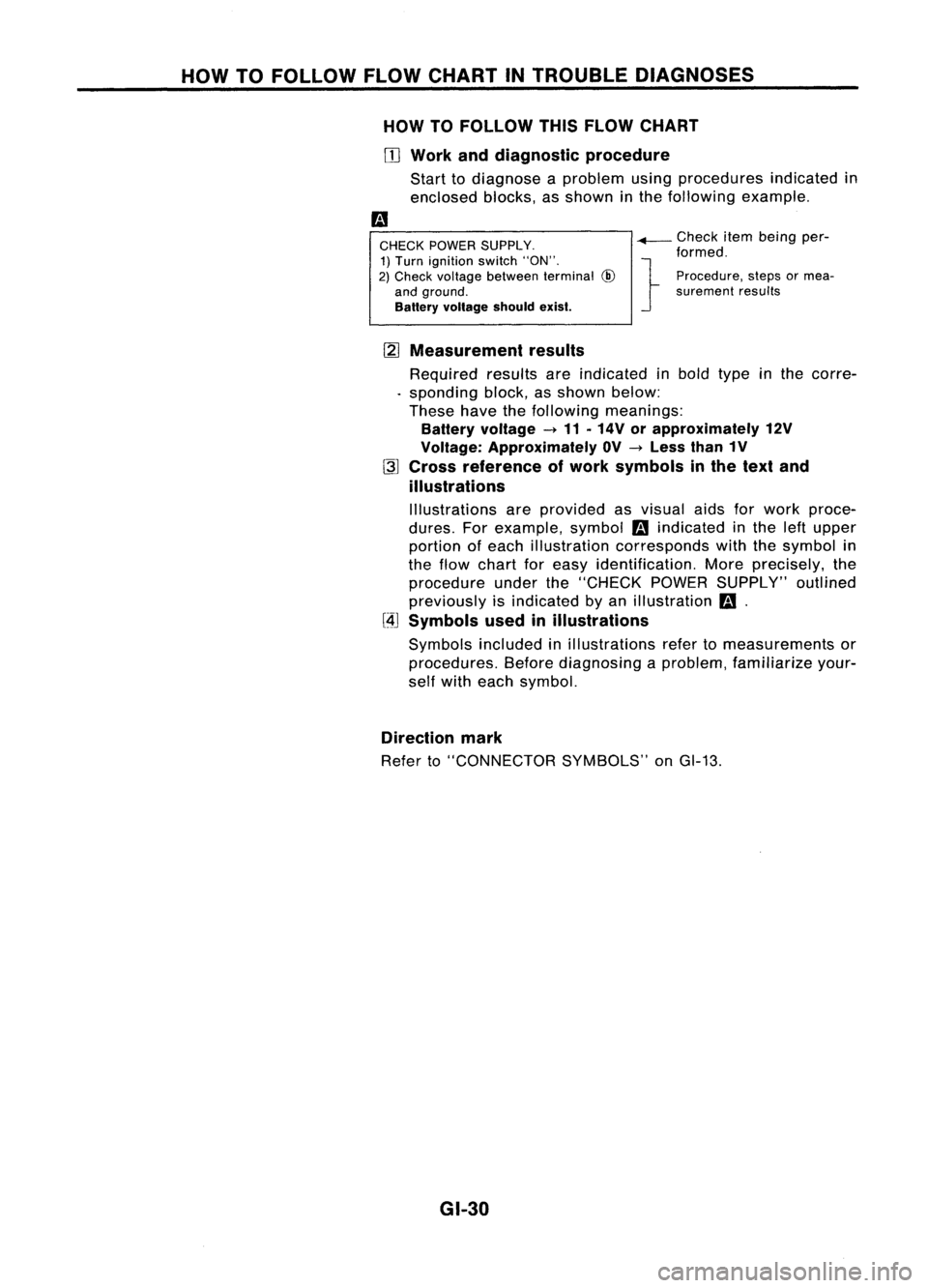
HOW TOFOllOW THISFLOW CHART
OJ
Work anddiagnostic procedure
Start todiagnose aproblem usingprocedures indicatedin
enclosed blocks,asshown inthe following example.
CHECK POWER SUPPLY.
1) Turn ignition switch"ON".
2) Check voltage between terminal
@
and ground.
Battery voltage shouldexist.
-+-
Check itembeing per-
formed.
} Procedure, stepsormea-
surement results
[2]
Measurement results
Required resultsareindicated inbold type inthe corre-
. sponding block,asshown below:
These havethefollowing meanings:
Battery voltage -11 .14V orapproximately 12V
Voltage: Approximately OV-Less than1V
~ Cross reference ofwork symbols inthe text and
illustrations
Illustrations areprovided asvisual aidsforwork proce-
dures. Forexample, symbol
m
indicated inthe leftupper
portion ofeach illustration corresponds withthesymbol in
the flow chart foreasy identification. Moreprecisely, the
procedure underthe"CHECK POWERSUPPLY" outlined
previously isindicated byan illustration
m.
[4J
Symbols usedinillustrations
Symbols includedinillustrations refertomeasurements or
procedures. Beforediagnosing aproblem, familiarize your-
self with each symbol.
Direction mark
Refer to"CONNECTOR SYMBOLS"onGI-13.
GI-30
Page 1385 of 1701
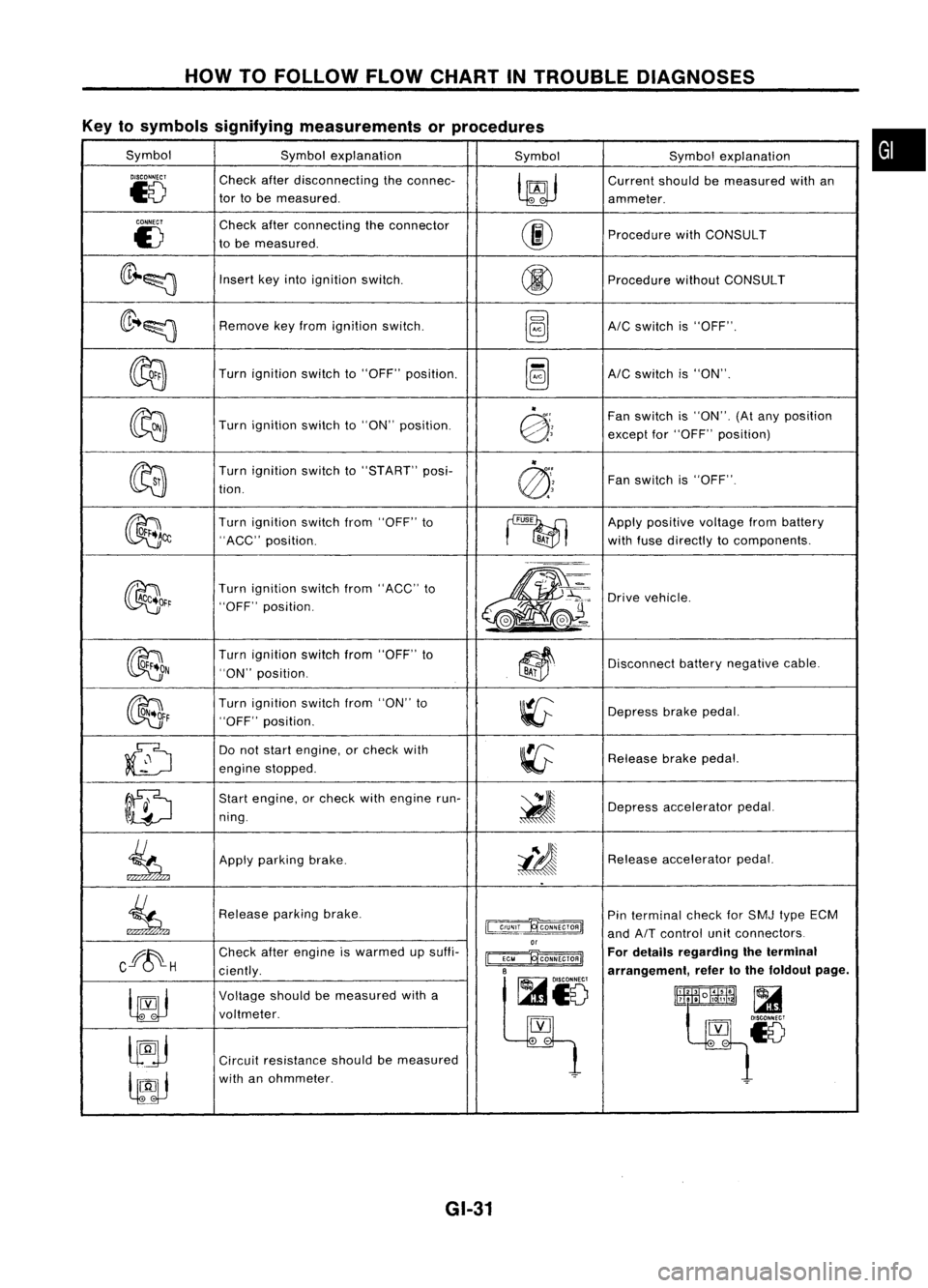
HOWTOFOLLOW FLOWCHART INTROUBLE DIAGNOSES
Key tosymbols signifying measurements orprocedures
Symbol Symbolexplanation
SymbolSymbolexplanation
DISCONNECT
Checkafterdisconnecting theconnec-
~
Current
shouldbemeasured withan
~8
tor
tobe measured.
ammeter.
CONNECT
Checkafterconnecting theconnector
00
E)
tobe measured. Procedure
withCONSULT
(lr~~
Insert
keyinto ignition switCh.
@
Procedure
withoutCONSULT
(lr ..~
Remove
keyfrom ignition switch.
~AIC
switch is"OFF".
~
Turn
ignition switchto"OFF" position.
~AIC
switch is"ON".
~
"
Fanswitch is"ON". (Atany position
Turn ignition switchto"ON" position.
@:;
exceptfor"OFF" position)
~ "
Turn ignition switchto"START" posi-
@'~
Fan
switch is"OFF".
tion.
~~
Turn
ignition switchfrom"OFF" to
~
Apply
positive voltagefrombattery
"ACC" position.
BA;
withfuse directly tocomponents.
~~r
Turn
ignition switchfrom"ACC" to
m-
~'~:
Drive
vehicle.
"OFF" position.
,.-=.
L
@J~ ..
~(e.-
OON
Turn
ignition switchfrom"OFF" to
~~
Disconnect
batterynegative cable.
"ON" position.
BAi
~F
Turn
ignition switchfrom"ON" to
~
Depress
brakepedal.
"OFF" position.
~
Do
not start engine, orcheck with
~
Release
brakepedal.
engine stopped.
ID
Start
engine, orcheck withengine run-
~
ning. Depress
accelerator pedal.
.
.
~
Apply
parking brake.
i!J
Release
accelerator pedal.
..
~
Release
parkingbrake.
~
Pin
terminal checkforSMJ typeECM
and
AIT
control unitconnectors
or
Cff~H
Check
afterengine iswarmed upsuffi-
~ For
details regarding theterminal
ciently.
B
arrangement,refertothe foldout page.
~io
~
Voltage
shouldbemeasured witha
lltlllliR~
t~~~18
voltmeter.
[YJ
lJ9j
.
-
Circuit resistance shouldbemeasured
lfJJ
with
anohmmeter.
~
GI-31
•
Page 1386 of 1701
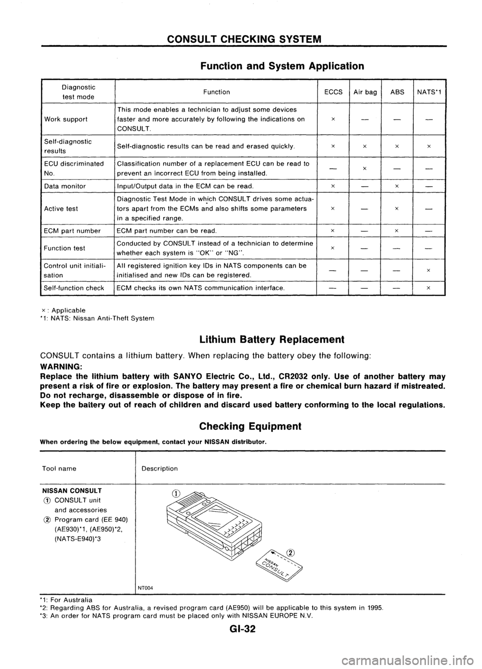
CONSULTCHECKING SYSTEM
Function andSystem Application
Diagnostic FunctionECCSAirbag ASS NATS*1
test mode
Thismode enables atechnician toadjust somedevices
Work support fasterandmore accurately byfollowing theindications on
x
- --
CONSULT.
Self-diagnostic Self-diagnosticresultscanberead anderased quickly.
x
x x
x
results
ECU discriminated Classification
numberofareplacement ECUcanberead to
-
x
- -
No. preventanincorrect ECUfrom being installed.
Data monitor Input/Output
datainthe ECM canberead.
x
-
x
-
Diagnostic TestMode inwh.ich CONSULT drivessomeactua-
Active test tors
apart fromtheECMs andalso shifts some parameters
x
-
x
-
in aspecified range.
ECM partnumber ECM
partnumber canberead.
x
-
x
-
Function test Conducted
byCONSULT insteadofatechnician todetermine
x
- --
whether eachsystem is"OK" or"NG".
Control unitinitiali- Allregistered ignitionkeyIDsinNATS components canbe
- -
-
x
sation initialisedandnew IDscan beregistered.
Self-function checkECM
checks itsown NATS communication interface.
--
-
x
x :Applicable
*1: NATS: Nissan Anti-Theft System
LithiumBatteryReplacement
CONSUL Tcontains alithium battery. Whenreplacing thebattery obeythefollowing:
WARNING: Replace thelithium battery withSANYO ElectricCo.,ltd., CR2032 only.Useofanother batterymay
present arisk offire orexplosion. Thebattery maypresent afire orchemical burnhazard ifmistreated.
Do not recharge, disassemble ordispose ofinfire.
Keep thebaitery outofreach ofchildren anddiscard usedbattery conforming tothe local regulations.
Checking Equipment
When ordering thebelow equipment, contactyourNISSAN distributor.
Tool name
NISSAN CONSULT
CD
CONSULT unit
and accessories
@
Program card(EE940)
(AE930)*1, (AE950)*2,
(NATS-E940)*3 Description
NT004
* 1: For Australia
*2: Regarding ASSforAustralia, arevised program card(AE950) willbeapplicable tothis system in1995.
*3: An order forNATS program cardmust beplaced onlywithNISSAN EUROPE N.V.
GI-32
Page 1399 of 1701
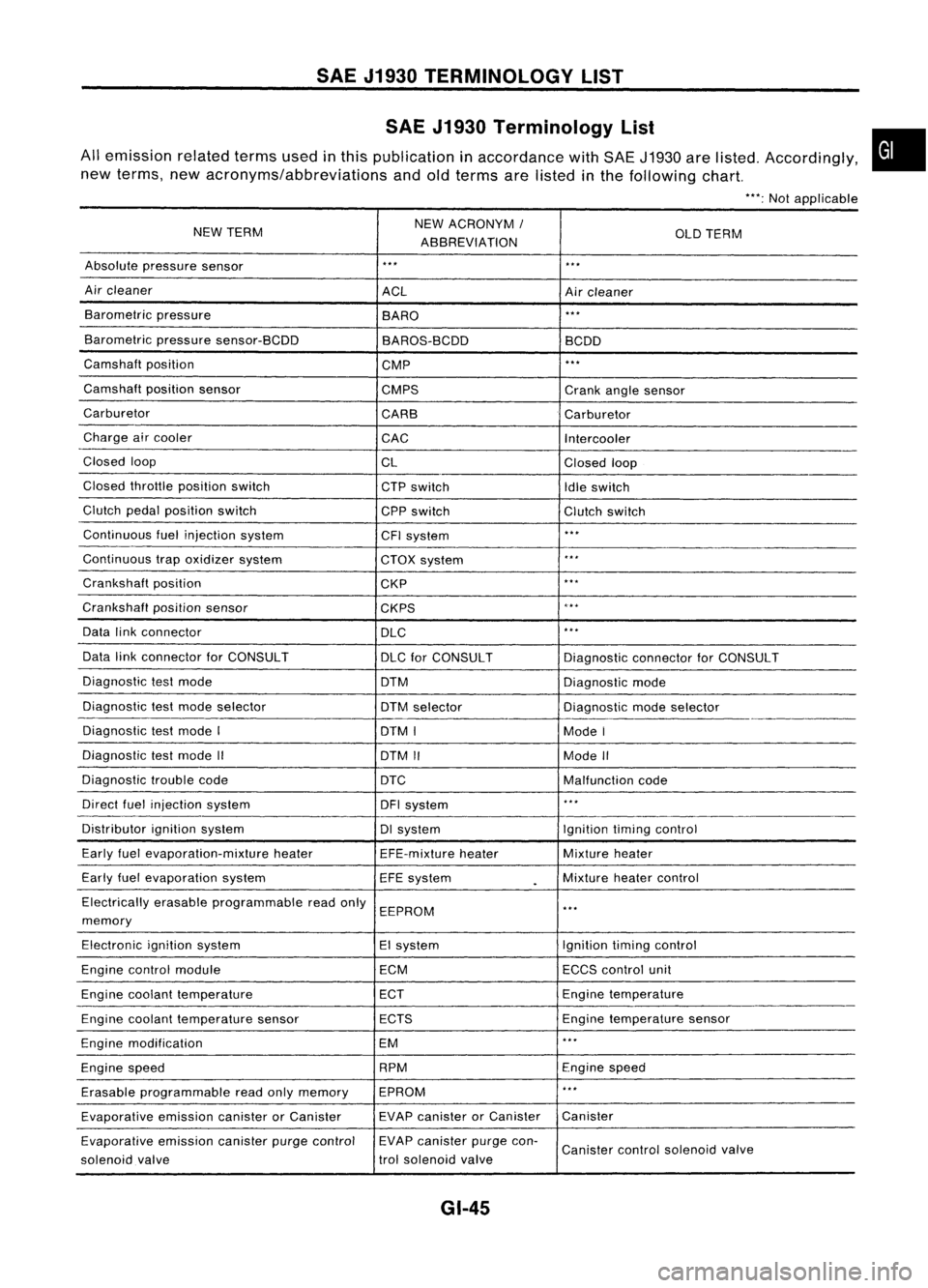
SAEJ1930 TERMINOLOGY LIST
SAE J1930 Terminology List
All emission relatedtermsusedinthis publication inaccordance withSAE J1930 arelisted. Accordingly,
new terms, newacronyms/abbreviations andoldterms arelisted inthe following chart.
"':Not applicable
NEW TERM NEW
ACRONYM /
ABBREVIATION OLD
TERM
Absolute pressure sensor
'" '"
Air cleaner
ACLAircleaner
Barometric pressure
BARO
."
Barometric pressuresensor-BCDD
BAROS-BCDD BCDD
Camshaft position
CMP
'"
Camshaft positionsensor
CMPS Crankanglesensor
Carburetor CARBCarburetor
Charge aircooler
CACIntercooler
Closed loop
CLClosedloop
Closed throttle position switch
CTPswitch
Idleswitch
Clutch pedalposition switch
CPPswitch Clutchswitch
Continuous fuelinjection system
CFIsystem
'"
Continuous trapoxidizer system
CTOXsystem
...
Crankshaft position
CKP
'"
Crankshaft positionsensor
CKPS
~.**
Data linkconnector
DLC
,
..
Data linkconnector forCONSULT
DLCforCONSULT DiagnosticconnectorforCONSULT
Diagnostic testmode
DTMDiagnosticmode
Diagnostic testmode selector
DTMselector Diagnosticmodeselector
Diagnostic testmode I
DTMI ModeI
Diagnostic testmode II
DTMII ModeII
Diagnostic troublecode
DTC Malfunctioncode
Direct fuelinjection system
DFIsystem
..
,
Distributor ignitionsystem DIsystem Ignitiontimingcontrol
Early fuelevaporation-mixture heater
EFE-mixtureheater Mixture
heater
Early fuelevaporation system
EFEsystem
.
Mixture
heatercontrol
Electrically erasableprogrammable readonly
EEPROM
'"
memory
Electronic ignitionsystem EIsystem Ignitiontimingcontrol
Engine control module ECMECCScontrol unit
Engine coolant temperature ECTEngine
temperature
Engine coolant temperature sensor ECTS Engine
temperature sensor
Engine modification EM
'"
Engine speed RPM
Enginespeed
Erasable programmable readonlymemory EPROM
'"
Evaporative emissioncanisterorCanister EVAP
canister orCanister Canister
Evaporative emissioncanisterpurgecontrol EVAP
canister purgecon-
Canister controlsolenoid valve
solenoid valve trol
solenoid valve
GI-45
•
Page 1400 of 1701
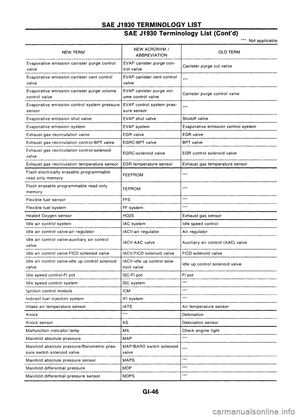
SAEJ1930 TERMINOLOGY LIST
SAE J1930 Terminology List(Cont'd)
***:
Not applicable
NEW TERM NEW
ACRONYM /
OLDTERM
ABBREVIATION
Evaporative emissioncanisterpurgecontrol EVAPcanister purgecon-
Canister purgecutvalve
valve trol
valve
Evaporative emissioncanisterventcontrol EVAPcanister ventcontrol
***
valve valve
Evaporative emissioncanisterpurgevolume EVAPcanister purgevol-
Canister purgecontrol valve
control valve ume
control valve
Evaporative emissioncontrolsystem pressure EVAP
control system pres-
***
sensor suresensor
Evaporative emissionshutvalve EVAP
shutvalve Shutoffvalve
Evaporative emissionsystem EVAPsystem Evaporative
emissioncontrolsystem
Exhaust gasrecirculation valve EGR
valve EGRvalve
Exhaust gasrecirculation control-BPTvalveEGRC-BPT valve BPT
valve
Exhaust gasrecirculation control-solenoid
EGRC-solenoidvalveEGR
control solenoid valve
valve
Exhaust gasrecirculation temperaturesensorEGRtemperature sensorExhaustgastemperature sensor
Flash electrically erasableprogrammable
FEEPROM
***
read onlymemory
Flash erasable programmable readonly
FEPROM
**.
memory
Flexible fuelsensor FFS
***
Flexible fuelsystem
FFsystem
***
Heated Oxygen sensor H02SExhaustgassensor
Idle aircontrol system lACsystem Idlespeed control
Idle aircontrol valve-air regulator IACV-airregulator Airregulator
Idle aircontrol valve-auxiliary aircontrol
IACV-AACvalve Auxiliaryaircontrol (AAC)valve
valve
Idle aircontrol valve-FICO solenoidvalve
IACV-FICDsolenoidvalve FICOsolenoid valve
Idle aircontrol valve-idle upcontrol solenoid IACV-idleupcontrol sole-
Idleupcontrol solenoid valve
valve noidvalve
Idle speed control-FI pot ISC-FIpot FIpot
Idle speed control system ISCsystem
***
Ignition controlmodule ICM
***
Indirect fuelinjection system IFIsystem
***
Intake airtemperature sensor IATS Airtemperature sensor
Knock
***
Detonation
Knock sensor
KSDetonation
sensor
Malfunction indicatorlamp MIL
Checkengine light
Manifold absolutepressure MAP
***
Manifold absolutepressure/Barometric pres-MAP/BARO switchsolenoid
***
sure switch solenoid valve valve
Manifold absolutepressure sensor MAPS
**.
Manifold differential pressure MOP
***
Manifold differential pressuresensor MOPS
***
GI-46