Page 1513 of 1701
ENGINEMAINTENANCE
SEF051PA SEF909P
*
NO FAIL
0
~y~r
GrJ-~
Data linkconnector forCONSULT
(Connect CHKandIGN terminals
with asuitable harness.)
•
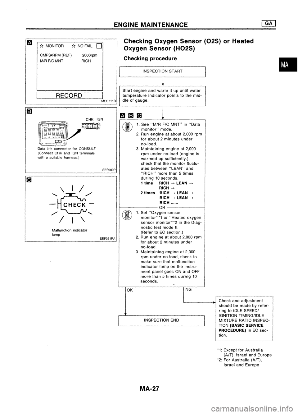
Checking
OxygenSensor(02S)orHeated
Oxygen Sensor(H02S)
Checking procedure
INSPECTION START
~
Start engine andwarm itup until water
temperature indicatorpointstothe mid-
dle ofgauge.
mm@]
1
00
1.
See "MIA
FIC
MNT" in"Data
monitor" mode.
2. Run engine atabout 2,000rpm
for about 2minutes under
no-load.
3. Maintaining engineat2,000
rpm under no-load (engine is
warmed upsufficiently.),
check thatthemonitor fluctu-
ates between "LEAN"and
"RICH" morethan5times
during 10seconds.
1
lime
RICH
->
LEAN
->
RICH
->
2
limes
RICH
->
LEAN
->
RICH
->
LEAN
->
RICH ......
OR
00
1.
Set' 'Oxygen sensor
monitor"*1 or"Heated oxygen
sensor monitor"*2 inthe Diag-
nostic testmode II.
(Refer toEC section.)
2. Run engine atabout 2,000rpm
for about 2minutes under
no-load.
3. Maintaining engineat2,000
rpm under no-load, checkto
make surethatmalfunction
indicator lamponthe instru-
ment panel goesONand OFF
more than5times during 10
seconds.
OK NG
Checkandadjustment
should bemade byrefer-
ring toIDLE SPEEDI
I
IGNITION
TIMINGIIDLE
INSPECTION END
MIXTURERATIOINSPEC-
TION
(BASIC SERVICE
PROCEDURE)
inEC sec-
tion.
I
MEC711B
2000rpm
RICH
RECORD
Malfunction indicator
lamp \
I/
'e/'
-
CHECK-
/
"
/ I\
CMPS'RPM
(REF)
MIR FIC
MNT
*
MONITOR
*1:Except forAustralia
(A/T),
Israel andEurope
*2: For Australia
(A/T),
Israel andEurope
MA-27
Page 1515 of 1701
FrontFront
CiIt
LOOSEN
'--
Radiator ENGINE
MAINTENANCE
Changing EngineCoolant
WARNING:
To avoid being scalded, neverchange thecoolant whenthe
engine ishot.
-DRAINING ENGINECOOLANT-
1. Turn ignition switch"ON".Moveheater "TEMP" control
knob allthe way to"HOT".
2. Open radiator drainplugatthe bottom ofradiator, and
remove radiator cap.
3. Remove reservoir tank,drain coolant, thenclean reservoir
tank. Install ittemporarily.
• Becareful nottoallow coolant tocontact drivebelts.
•
DI1211M MA-29
Page 1518 of 1701
![NISSAN ALMERA N15 1995 Service Manual ENGINEMAINTENANCE [][]
Checking CoolingSystem(Cont'd)
Pull thenegative-pressure valvetoopen it.Check thatitcloses
completely whenreleased.
CHECKING COOLINGSYSTEMFORLEAKS
Apply pressure tothe c NISSAN ALMERA N15 1995 Service Manual ENGINEMAINTENANCE [][]
Checking CoolingSystem(Cont'd)
Pull thenegative-pressure valvetoopen it.Check thatitcloses
completely whenreleased.
CHECKING COOLINGSYSTEMFORLEAKS
Apply pressure tothe c](/manual-img/5/57349/w960_57349-1517.png)
ENGINEMAINTENANCE [][]
Checking CoolingSystem(Cont'd)
Pull thenegative-pressure valvetoopen it.Check thatitcloses
completely whenreleased.
CHECKING COOLINGSYSTEMFORLEAKS
Apply pressure tothe cooling systemwithcaptester tocheck
f~r leakage.
Testing pressure:
157 kPa (1.57 bar,1.6kg/cm
2,
23psi)
CAUTION:
Higher pressure thanthespecified valuemaycause damage to
radiator.
SMA811C
SMA803A
Checking
FuelLines
Inspect fuellines andtank forimproper attachment, leaks,
cracks, damage, looseconnections, chafingordeterioration.
If necessary, repairorreplace faultyparts.
3 (0.12) Unit:mm(in)
_._-- --,"'~'r---1
"
,
-
-
---;--,
-,---
•• J..
_J- __
28 (1.10)
~ Fuel hose clamps
1.0 -1.5 N.m
(0.10 -0.15 kg-m,
8.7 -13.0 in-Ib)
MMA104A
• FUEL PRESRELEASE.
0
FUEL PUMP WILLSTOP BY
TOUCHING STARTDURING
IDLE_
CRANK AFEW TIMES AFTER
ENGINE STALL.
---S-T~-RT--
SEF823KCAUTION:
Tighten high-pressure rubberhoseclamp sothat clamp endis
3 mm (0.12 in)from hose end.
Tightening torquespecifications arethesame forallrubber
hose clamps.
Ensure thatscrew doesnotcontact adjacent parts.
Changing FuelFilter
WARNING:
Before removing fuelfilter, release fuelpressure fromfuelline
to eliminate danger.
rF.i\
1.Start engine.
~ 2.Perform "FUELPRESSURE RELEASE"in"WORK
SUPPORT" modewithCONSULT.
3. After engine stalls,crankengine twoorthree times
to make surethatfuel pressure isreleased.
4. Turn ignition switchoff.
MA-32
Page 1519 of 1701
ENGINEMAINTENANCE ~
Changing FuelFilter (Cont'd)
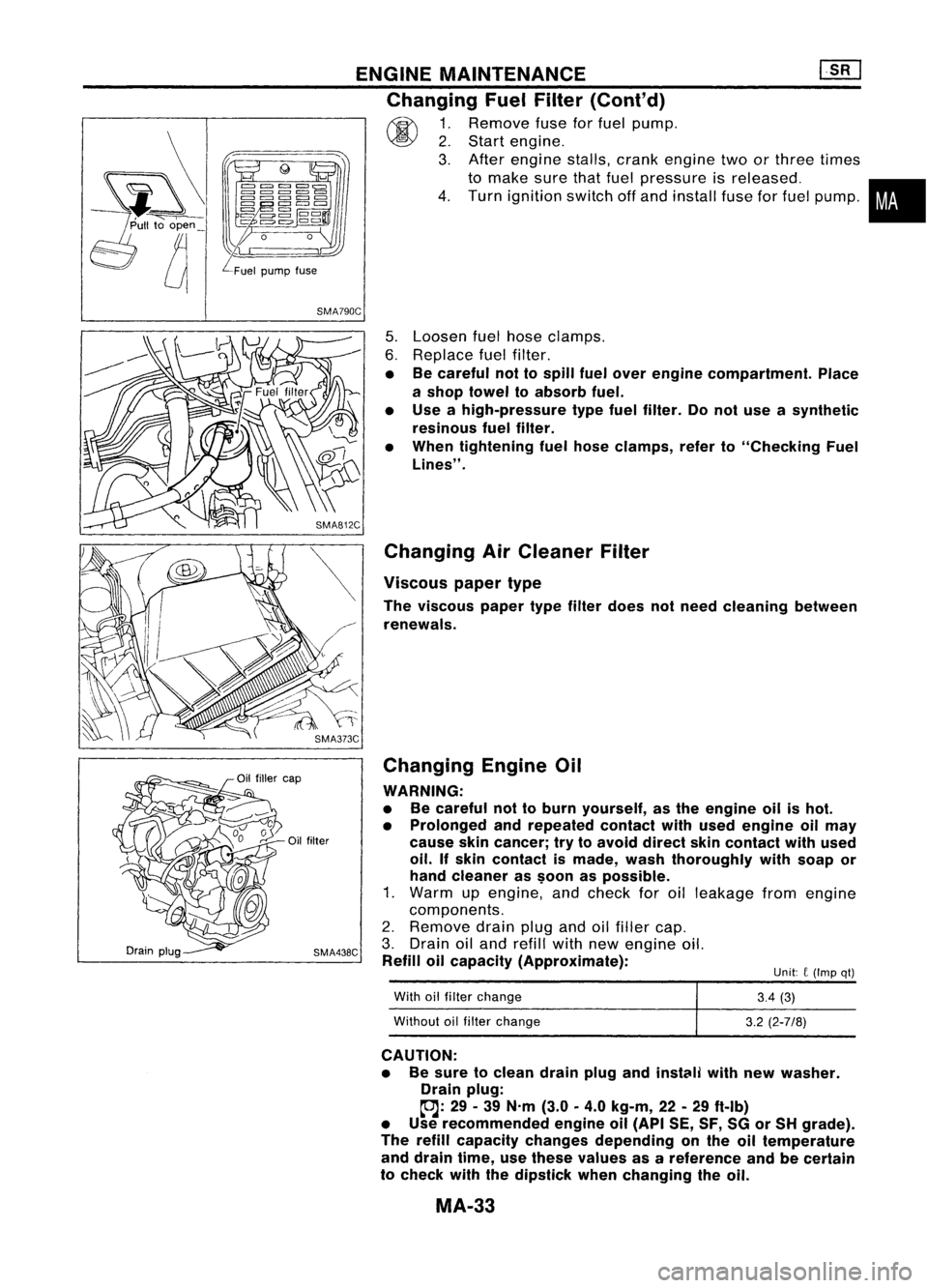
~ 1.Remove fuseforfuel pump.
~ 2.Start engine.
3. After engine stalls,crankengine twoorthree times
to make surethatfuel pressure isreleased. •
4. Turn ignition switchoffand install fuseforfuel pump.
i
Unit: C(Imp qt)
SMA790C
5.Loosen fuelhose clamps.
6. Replace fuelfilter.
• Becareful nottospill fuelover engine compartment. Place
a shop towel toabsorb fuel.
• Use ahigh-pressure typefuelfilter. Donot use asynthetic
resinous fuelfilter.
• When tightening fuelhose clamps, referto"Checking Fuel
Lines" .
Changing AirCleaner Filter
Viscous papertype
The viscous papertypefilter does notneed cleaning between
renewals.
Changing EngineOil
WARNING:
• Becareful nottoburn yourself, asthe engine oilishot.
• Prolonged andrepeated contactwithused engine oilmay
cause skincancer; trytoavoid direct skincontact withused
oil. Ifskin contact ismade, washthoroughly withsoap or
hand cleaner as$oon aspossible.
1. Warm upengine, andcheck foroilleakage fromengine
components.
2. Remove drainplugandoilfiller cap.
3. Drain oiland refill withnewengine oil.
Refill oilcapacity (Approximate):
With oilfilter change
Without oilfilter change
3.4
(3)
3.2 (2-7/8)
CAUTION: • Besure toclean drainplugandinstClili withnewwasher.
Drain plug:
~: 29-39 N'm (3.0
0
4.0 kg-m, 22-29 ftolb)
• Use recommended engineoil(API SE,SF,SGorSH grade).
The refill capacity changes depending onthe oiltemperature
and drain time,usethese values asareference andbecertain
to check withthedipstick whenchanging theoil.
MA-33
Page 1520 of 1701
ENGINEMAINTENANCE [}[]
Changing EngineOil(Cont'd)
4. Check oillevel.
5. Start engine andcheck areaaround drainplugandoilfilter
for oilleakage.
6. Run engine forafew minutes, thenturnitoff. After several
minutes, checkoillevel.
Refill oil10this
"H" level.
Do not overfill.
SMA390C
Changing OilFilter
1. Remove oilfilter withTool.
WARNING:
Be careful nottoburn yourself, asthe engine andtheengine
oil are hot.
2. Clean oilfilter mounting surfaceoncylinder block.Coat
rubber sealofnew oilfilter withengine oil.
2/3
ofaturn
-------
OK SMA010
3.Screw inthe oilfilter untilaslight resistance isfelt, then
tighten anadditional 2/3turn.
4. Add engine oil.
Refer toChanging EngineOil.
• Clean excess oilfrom engine.
Changing SparkPlugs(Platinum-tipped type)
1. Disconnect ignitionwiresfromspark plugsatboot. Donot
pull onthe wire.
MA-34
Page 1521 of 1701
g
16
mm
(0.63
In)
Wrench
withamagnet
to hold spark plug
ENGINE
MAINTENANCE
lliJ
Changing SparkPlugs(Platinum-tipped type)
(Cont'd)
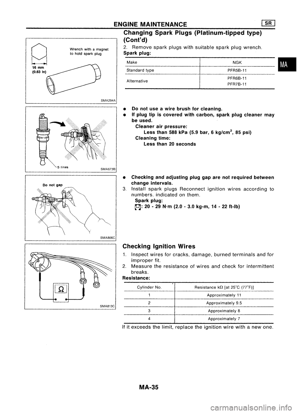
2. Remove sparkplugswithsuitable sparkplugwrench.
Spark plug:
Make NGK
•
Standard
type
PFR5B-11
Alternative PFR6B-11
PFR7B-11
SMA294A
Do
not
gap •
Donot use awire brush forcleaning.
• If
plug tipiscovered withcarbon, sparkplugcleaner may
be used.
Cleaner airpressure:
Less than588kPa (5.9bar, 6kg/cm
2,
85psi)
Cleaning time:
Less than20seconds
• Checking andadjusting pluggaparenotrequired between
change intervals.
3. Install sparkplugsReconnect ignitionwiresaccording to
numbers. indicatedonthem.
Spark plug:
~: 20-29 N'm (2.0-3.0 kg-m, 14-22 ft-Ib)
SMA806C Checking IgnitionWires
1. Inspect wiresforcracks, damage, burnedterminals andfor
improper fit.
2. Measure theresistance ofwires andcheck forintermittent
breaks.
Resistance:
SMA813C
Cylinder
No.
2
3
4
Resistance
kQ[at25°C (77°F)]
Approximately 11
Approximately 9.5
Approximately 8
Approximately 7
If itexceeds thelimit, replace theignition wirewithanew one.
MA-35
Page 1523 of 1701
ENGINEMAINTENANCE
SEF051PA SEF909P
*
NO FAIL
D
Malfunction indicator
lamp
•
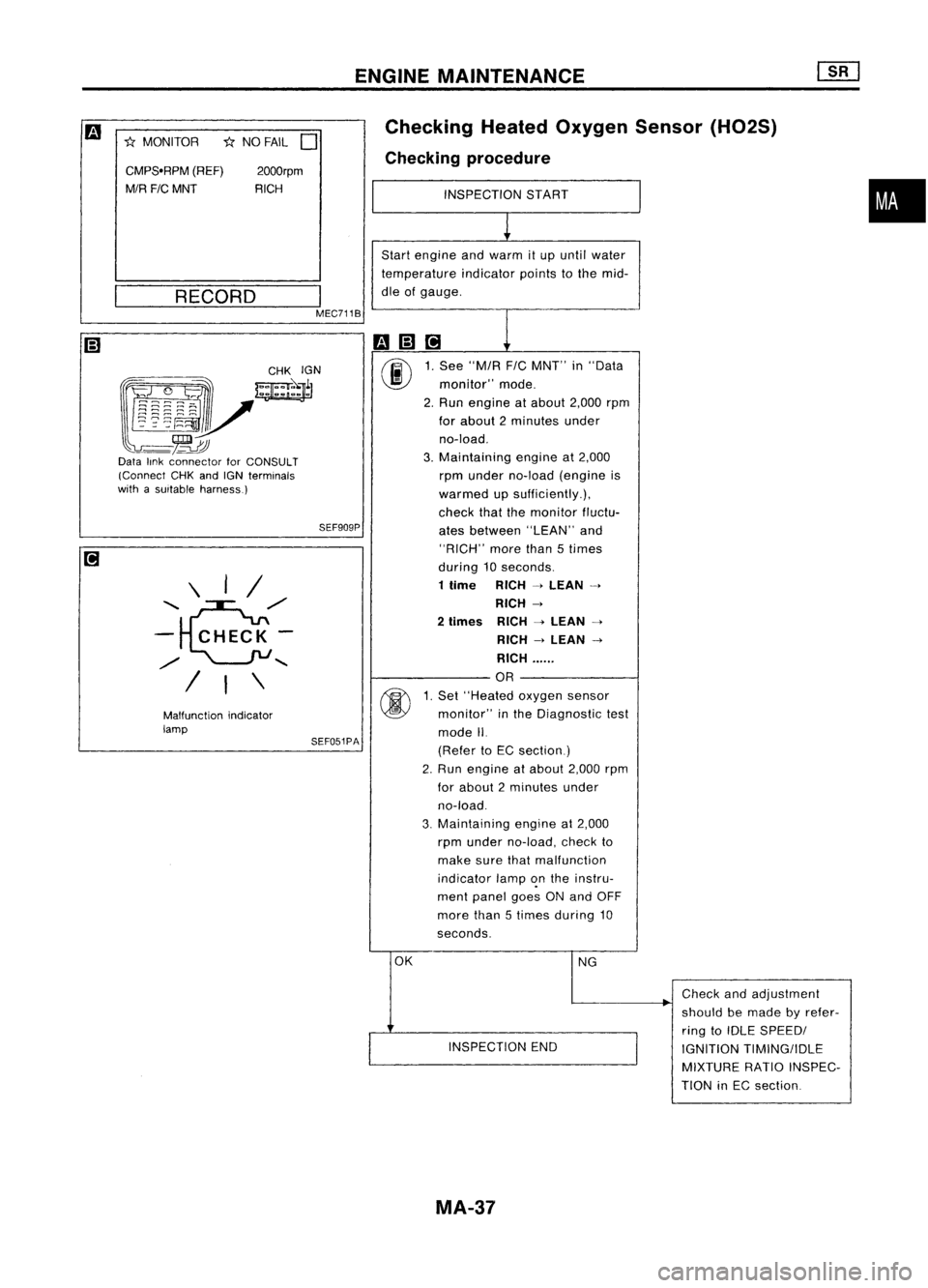
Checking
HeatedOxygen Sensor(H02S)
Checking procedure
INSPECTION START
1
Start engine andwarm itup until water
temperature indicatorpointstothe mid-
dle ofgauge.
m(;]ri
1
00
1.
See "M/R F/CMNT" in"Data
monitor" mode.
2. Run engine atabout 2,000rpm
for about 2minutes under
no-load.
3. Maintaining engineat2,000
rpm under no-load (engine is
warmed upsufficiently.),
check thatthemonitor fluctu-
ates between "LEAN"and
"RICH" morethan5times
during 10seconds.
1 time RICH
-4
LEAN
-4
RICH
-4
2
times RICH
-4
LEAN
-4
RICH
-4
LEAN
-4
RICH ......
OR
@
1.
Set "Heated oxygensensor
monitor" inthe Diagnostic test
mode II.
(Refer toEC section)
2. Run engine atabout 2,000rpm
for about 2minutes under
no-load.
3. Maintaining
engineat2,000
rpm under no-load, checkto
make surethatmalfunction
indicator lamp~nthe instru-
ment panel goesONand OFF
more than5times during 10
seconds.
OK NG
.
Check
andadjustment
should bemade byrefer-
ring toIDLE SPEEDI
INSPECTION END
IGNITIONTIMING/IDLE
MIXTURE RATIOINSPEC-
TION inEC section
2000rpm
RICH
\ I/
........ e./
- CHECK-
./
........
/ I\
CMPS.RPM
(REF)
M/R FICMNT
*
MONITOR
__ R_E_C_O_R_D __
I
MEC711B
~~~~:?~;~
~~r
l~~~~V
-~~
Data linkconnector forCONSULT
(Connect CHKandIGN terminals
with asuitable harness.)
MA-37
Page 1628 of 1701
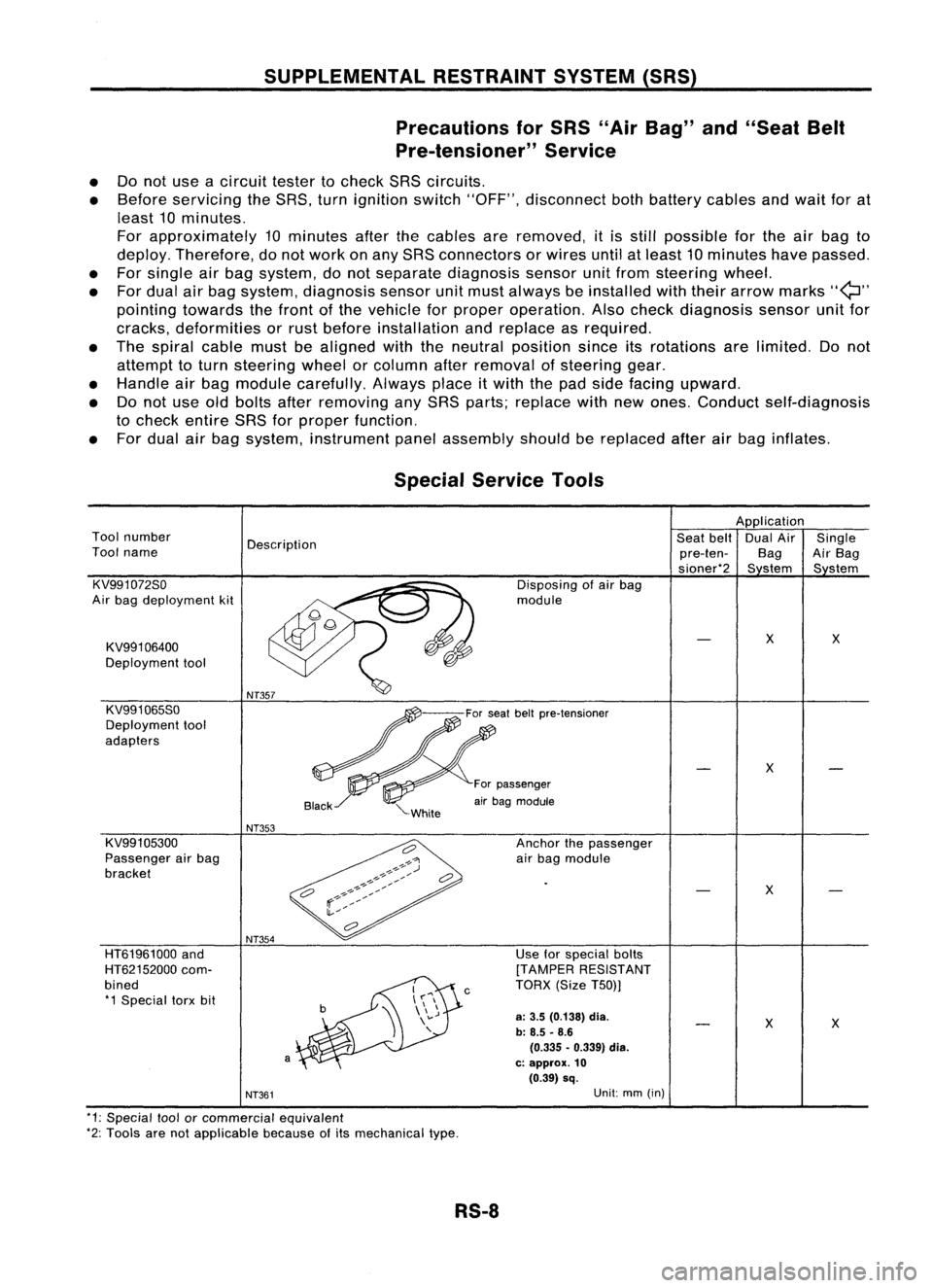
SUPPLEMENTALRESTRAINTSYSTEM(SRS)
Precautions forSRS "AirBag" and"Seat Belt
Pre-tensioner" Service
• Donot use acircuit testertocheck SRScircuits.
• Before servicing theSRS. turnignition switch"OFF", disconnect bothbattery cablesandwait forat
least 10minutes.
For approximately 10minutes afterthecables areremoved, itis still possible forthe airbag to
deploy. Therefore, donot work onany SRS connectors orwires untilatleast 10minutes havepassed.
• For single airbag system, donot separate diagnosis sensorunitfrom steering wheel.
• For dual airbag system. diagnosis sensorunitmust always beinstalled withtheir arrow marks
"Q"
pointing towards thefront ofthe vehicle forproper operation. Alsocheck diagnosis sensorunitfor
cracks. deformities orrust before installation andreplace asrequired.
• The spiral cablemustbealigned withtheneutral position sinceitsrotations arelimited. Donot
attempt toturn steering wheelorcolumn afterremoval ofsteering gear.
• Handle airbag module carefully. Alwaysplaceitwith thepad side facing upward.
• Donot use oldbolts afterremoving anySRS parts; replace withnewones. Conduct self-diagnosis
to check entire SRSforproper function.
• For dual airbag system, instrument panelassembly shouldbereplaced afterairbag inflates.
X
X
Use
forspecial bolts
[TAMPER RESISTANT
TORX (SizeT50))
a:
3.5 (0.138)
dia.
b: 8.5 -8.6
(0.335 •0.339) dia.
c: approx.
10
(0.39) sq.
c
NT354
a
HT61961000
and
HT62152000 com-
bined *1 Special torxbit
Special
Service Tools
Application
Tool number
Description Seat
belt DualAir Single
Tool name
pre-ten-BagAirBag
sioner*2 Sstem Sstem
KV991072So Disposingofair bag
Air bag deployment kit module
KV991 06400
X
X
Deployment tool
KV991065So
Deployment tool
adapters
X
For passenger
air bag module
NT353
KV991 05300 Anchorthepassenger
Passenger airbag
airbag module
bracket
X
NT361
Unit:
mm(in)
*1: Special toolorcommercial equivalent
*2: Tools arenotapplicable becauseofits mechanical type.
RS-8