1995 NISSAN ALMERA N15 steering wheel
[x] Cancel search: steering wheelPage 891 of 1701
![NISSAN ALMERA N15 1995 Service Manual TROUBLEDIAGNOSIS FORNON-DETECTABLE ITEMS
@K]
Power Steering OilPressure Switch(Cont'd)
@:
ForAustralia
@:
Except forAustralia SEF176R
Repair
harness orcon-
nectors.
CHECK INPUTSIGNAL CIRCUIT. NISSAN ALMERA N15 1995 Service Manual TROUBLEDIAGNOSIS FORNON-DETECTABLE ITEMS
@K]
Power Steering OilPressure Switch(Cont'd)
@:
ForAustralia
@:
Except forAustralia SEF176R
Repair
harness orcon-
nectors.
CHECK INPUTSIGNAL CIRCUIT.](/manual-img/5/57349/w960_57349-890.png)
TROUBLEDIAGNOSIS FORNON-DETECTABLE ITEMS
@K]
Power Steering OilPressure Switch(Cont'd)
@:
ForAustralia
@:
Except forAustralia SEF176R
Repair
harness orcon-
nectors.
CHECK INPUTSIGNAL CIRCUIT. NG
Check thefollowing .
1. Disconnect ECMharness connector.
......---..
•Harness connectors
2. Check harness continuity between
aD,
(MID
ECM terminal
@
or
@
and terminal •
Harness connectors
G).
@,@or@,
Continuity shouldexist.
If
OK, check harness forshort. •
Harness foropen or
OK short
between ECMand
power steering oilpres-
sure switch
If NG, repair harness or
connectors.
CHECK COMPONENT NG
Replace powersteering
(Power steering oilpressure switch).
--...
oilpressure switch.
Refer to"COMPONENT INSPECTION"
below.
OK
Disconnect andreconnect harnesscon-
nectors inthe circuit. Thenretest.
Trouble isnot fixed.
Check ECMpinterminals fordamage or
the connection ofECM harness connec-
tor. Reconnect ECMharness connector
and retest.
@
1
CHECK GROUND CIRCUIT.
1. Turn ignition switch"OFF".
2. Disconnect powersteering oilpres-
sure switch harness connector.
3. Check harness continuity between
terminal
@
and engine ground.
Continuity shouldexist.
AEC760
IfOK, check harness forshort.
~i5
[i
c:ITb
~i5
ECM
Ef
CONNECTOR
II
43 25
II
INSPECTIONEND
Power steering oilpressure switch
1. Disconnect powersteering oilpressure switchharness con-
nector thenstart engine.
2. Check continuity betweenterminals
@.
[At
IV
ID
~ COMPONENT
INSPECTION
Conditions
Steering wheelisbeing turned
Steering wheelisnot being turned Continuity
Yes
No
AEC762
IfNG, replace powersteering oilpressure switch.
EC-172
Page 980 of 1701
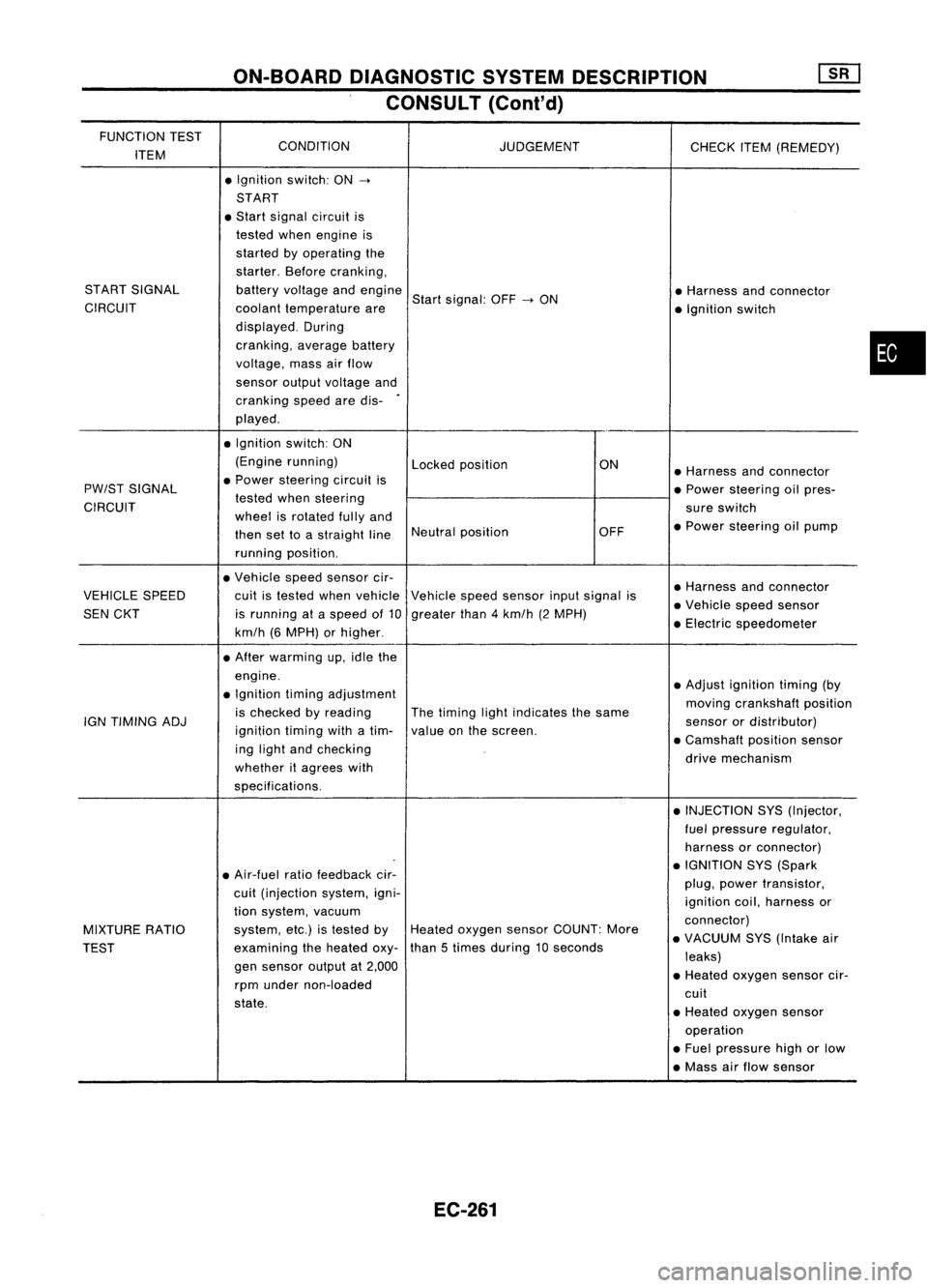
ON-BOARDDIAGNOSTIC SYSTEMDESCRIPTION
CONSULT (Cont'd)
FUNCTION TEST
CONDITION
ITEM JUDGEMENT
CHECKITEM(REMEDY)
• Ignition switch:ON
->
START
• Start signal circuit is
tested whenengine is
started byoperating the
starter. Beforecranking,
START SIGNAL batteryvoltage andengine
Startsignal: OFF
->
ON •
Harness andconnector
CIRCUIT coolanttemperature are
•Ignition switch
displayed. During
cranking, averagebattery
voltage, massairflow
sensor outputvoltage and
cranking speedaredis-
.
played .
• Ignition switch:ON
(Engine running)
Lockedposition ON
•Harness andconnector
PW/ST SIGNAL •
Power steering circuitis
•Power steering oilpres-
CIRCUIT tested
whensteering
sureswitch
wheel isrotated fullyand
•Power steering oilpump
then settoastraight lineNeutral
position OFF
running position.
• Vehicle speedsensor cir-
•Harness andconnector
VEHICLE SPEED cuitistested whenvehicle Vehiclespeedsensor inputsignal is
•Vehicle speedsensor
SEN CKT isrunning ataspeed of10 greater than4km/h (2MPH)
•Electric speedometer
km/h (6MPH) orhigher .
• After warming up,idle the
engine. •Adjust ignition timing(by
• Ignition timingadjustment
movingcrankshaft position
is checked byreading Thetiming lightindicates thesame
IGN TIMING ADJ
ignitiontimingwithatim- valueonthe screen. sensor
ordistributor)
ing light andchecking •
Camshaft positionsensor
whether itagrees with drive
mechanism
specifications. •INJECTION SYS(Injector,
fuel pressure regulator,
harness orconnector)
• Air-fuel ratiofeedback cir- •
IGNITION SYS(Spark
cuit (injection system,igni- plug,
power transistor,
ignition coil,harness or
tion system, vacuum
connector)
MIXTURE RATIO system,
etc.)istested byHeated oxygen sensorCOUNT: More
•VACUUM SYS(Intake air
TEST examining
theheated oxy-than
5times during 10seconds
leaks)
gen sensor outputat2,000
•Heated oxygen sensorcir-
rpm under non-loaded
cuit
state. •Heated oxygen sensor
operation
• Fuel pressure highorlow
• Mass airflow sensor
EC-261
•
Page 990 of 1701
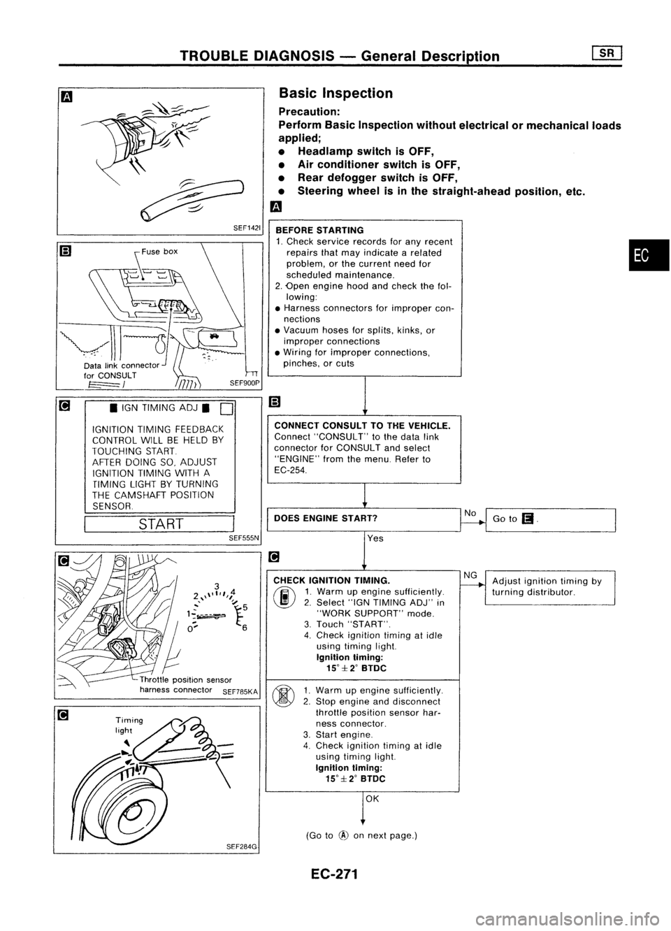
TROUBLEDIAGNOSIS -General Descrip_ti_on
1S_R_'
Basic Inspection
Precaution:
Perform BasicInspection withoutelectrical ormechanical loads
applied;
• Headlamp switchisOFF,
• Air conditioner switchisOFF,
• Rear defogger switchisOFF,
• Steering wheelisinthe straight-ahead position,etc.
m
BEFORE STARTING
1. Check service records forany recent •
repairs thatmay indicate arelated
problem, orthe current needfor
scheduled maintenance.
2. Open engine hoodandcheck thefol-
lowing:
• Harness connectors forimproper con-
nections
• Vacuum hosesforsplits, kinks,or
improper connections
• Wiring forimproper connections,
pinches, orcuts
Goto
(I.
No
CONNECT
CONSULTTOTHE VEHICLE.
Connect "CONSULT" tothe data link
connector forCONSULT andselect
"ENGINE" fromthemenu. Referto
EC-254.
DOES ENGINE START?
\\
~
~ SEF1421
START
•
IGN TIMING ADJ.
0
IGNITION TIMINGFEEDBACK
CONTROL WILLBEHELD BY
TOUCHING START
AFTER DOING SO,ADJUST
IGNITION TIMINGWITHA
TIMING LIGHTBYTURNING
THE CAMSHAFT POSITION
SENSOR.
SEF555N
Yes
CHECK IGNITION TIMING.
(ij\
1.Warm upengine sufficiently.
~ 2.Select "IGNTIMING ADJ"in
"WORK SUPPORT" mode.
3. Touch "START".
4. Check ignition timingatidle
using timing light.
Ignition timing:
15°::f:2° BTDC
~ 1Warm upengine sufficiently.
~ 2:
Stop engine anddisconnect
throttle position sensorhar-
ness connector.
3. Start engine.
4. Check ignition timingatidle
using timing light.
Ignition timing:
15°::f:2° BTDC
OK
(Go to
@
onnext page.) Adjust
ignition timingby
turning distributor.
EC-271
Page 997 of 1701
![NISSAN ALMERA N15 1995 Service Manual TROUBLEDIAGNOSIS -General Description
[]K]
CONSULT Reference ValueinData Monitor
Mode (Cont'd)
MONITOR ITEM
CONDITION SPECIFICATION
Steering wheelinneutral
position OFF
PW/ST SIGNAL
•Engine: NISSAN ALMERA N15 1995 Service Manual TROUBLEDIAGNOSIS -General Description
[]K]
CONSULT Reference ValueinData Monitor
Mode (Cont'd)
MONITOR ITEM
CONDITION SPECIFICATION
Steering wheelinneutral
position OFF
PW/ST SIGNAL
•Engine:](/manual-img/5/57349/w960_57349-996.png)
TROUBLEDIAGNOSIS -General Description
[]K]
CONSULT Reference ValueinData Monitor
Mode (Cont'd)
MONITOR ITEM
CONDITION SPECIFICATION
Steering wheelinneutral
position OFF
PW/ST SIGNAL
•Engine: Afterwarming up,idle theengine (forward
direction)
The steering wheelis
ON
turned
• Engine: Afterwarming up
Idle2.5-3.7 msec .
INJ PULSE •
Air conditioner switch:OFF
• Shift lever: "N"
• No-load 2,000
rpm 1.9-2.8 msec .
Idle 13-15° BTDC
IGN TIMING
ditto
2,000rpm Morethan25°BTDC
Idle 20-40%
IACV-AACIV ditto
2,000rpm
-
A/F ALPHA •Engine: Afterwarming up Maintaining
enginespeed
53-155%
at 2.000 rpm
AIR COND RLY •Air conditioner switch:OFF
-+
ON OFF
-+
ON
• Ignition switchis~urned toON (Operates for5seconds)
• Engine running andcranking ON
FUEL PUMP RLY
•When engine isstopped (stopsin1.0 seconds)
• Except asshown above OFF
Engine coolant temperature
is 94°C (201°F) orless for
AfT models. and99°C OFF
(210°F) orless for
M/T
mod-
els
• After warming upengine. idletheengine. Engine
coolant temperature
is between 95°C(203°F) and
COOLING FAN •Air conditioner switch:OFF
104°C(219°F) forA/T mod- LOW
• Vehicle stopped
elsonly
Engine coolant temperature
is 105°C (221°F) ormore for
A/T
models. and100°C HIGH
(212°F) ormore for
M/T
models
• Engine: Afterwarming up
IdleON
EGRC SOLIV •
Air conditioner switch:OFF
• Shift lever: "N"
• No-load 2.000
rpm OFF
EC-278
Page 1003 of 1701
![NISSAN ALMERA N15 1995 Service Manual TROUBLEDIAGNOSIS -General Description
[]:KJ
ECM Terminals andReference Value(Cont'd)
*Data arereference values.
TERMINAL WIRE
ITEM CONDITION *
DATA
NO. COLOR
/Ignitionswitch"ON'"
t NISSAN ALMERA N15 1995 Service Manual TROUBLEDIAGNOSIS -General Description
[]:KJ
ECM Terminals andReference Value(Cont'd)
*Data arereference values.
TERMINAL WIRE
ITEM CONDITION *
DATA
NO. COLOR
/Ignitionswitch"ON'"
t](/manual-img/5/57349/w960_57349-1002.png)
TROUBLEDIAGNOSIS -General Description
[]:KJ
ECM Terminals andReference Value(Cont'd)
*Data arereference values.
TERMINAL WIRE
ITEM CONDITION *
DATA
NO. COLOR
/Ignitionswitch"ON'"
t
"N" or"P" position
(A/T)
OV
35
G/OR
Neutral
position
Neutralposition
(M/T)
switch/lnhibitor switch
I'gnitionswitch"ON"I
BATTERYVOLTAGE
L
Except theabove gearposition (11
-14V)
I'gnition switch"OFF"I
OV
36 B/R Ignition
switch
Ilgnitionswitch"ON"I BATTERY
VOLTAGE
(11 -14V)
37 P/L Throttle
position sen-
pgnition switch"ON"I
Approximately5V
sor power supply
38 Powersupply forECM
Ilgnition switch"ON"I BATTERY
VOLTAGE
47 W/R
(11-14V)
39 B ECCSground IEngine
isrunning.1
Engineground
L
Idle speed
IEngine isrunning.!
L
Both airconditioner switchandblower fanApproximately
OV
41 G Air
conditioner switch switch
are"ON".
IEngine isrunning.1
BATTERYVOLTAGE
L
Airconditioner switchis"OFF". (11
-14V)
IEngine isrunning.1
OV
Power steering oil
L
Steering wheelisbeing turned.
43 PUlW
pressureswitch
IEngineisrunning.1
L
Steering wheelisnot being turned. 7
-9V
46 W/L Power
supply
I'gnitionswitch
"0FFj
BATTERY
VOLTAGE
(Back-up) (11-14V)
48 B ECCSground IEngine
isrunning.1
Engineground
L
Idle speed
109 W/L Currentreturn
Ilgnitionswitch"OFF"I BATTERY
VOLTAGE
(11 -14V)
101 RIB InjectorNo.1
103
G/B
InjectorNo.3
BATTERYVOLTAGE
110 Y/B InjectorNO.2 IEngine
isrunning.1
(11-14V)
112 LIB InjectorNO.4
EC-284
Page 1074 of 1701
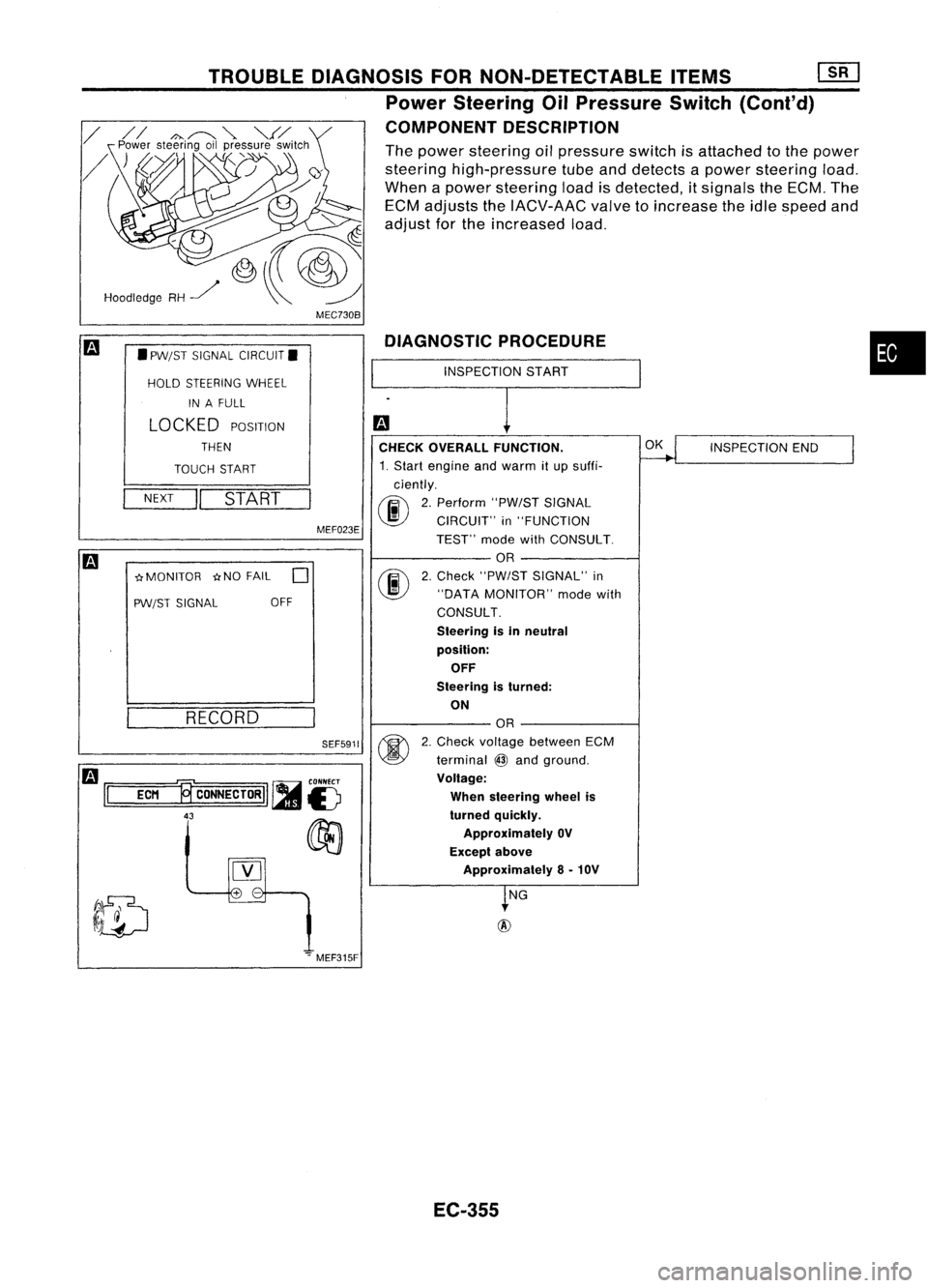
MEC730B
•
INSPECTION
START
DIAGNOSTIC
PROCEDURE
CHECK OVERALL FUNCTION.
~
INSPECTION
END
I
1. Start engine andwarm itup suffi-
ciently.
00
2.
Perform "PW/STSIGNAL
CIRCUIT" in"FUNCTION
TEST" modewithCONSULT.
OR
@
2.
Check "PW/ST SIGNAL" in
"DATA MONITOR" modewith
CONSULT.
Steering isin neutral
position: OFF
Steering isturned:
ON
OR
@
2.
Check voltage between ECM
terminal
@
and ground.
Voltage:
When steering wheelis
turned quickly.
Approximately OV
Except above
Approximately 8-10V
~NG
+
-
SEF5911
MEF023E
TROUBLE
DIAGNOSIS FORNON-DETECTABLE ITEMS[][]
Power Steering OilPressure Switch(Cont'd)
COMPONENT DESCRIPTION
The power steering oilpressure switchisattached tothe power
steering high-pressure tubeanddetects apower steering load.
When apower steering loadisdetected, itsignals theECM. The
ECM adjusts theIACV-AAC valvetoincrease theidle speed and
adjust forthe increased load.
RECORD
NEXT
II
START
•
PW/ST SIGNAL CIRCUIT.
HOLD STEERING WHEEL
IN AFULL
LOCKED
POSITION
THEN
TOUCH START
-crMONITOR -crNOFAIL
0
PW/ST SIGNAL OFF
Hoodledge
RH~
m
1='
=EC=M
=.,~
CONNECTORII ~
is
43
00
[Y]
.".MEF315F
EC-355
Page 1075 of 1701
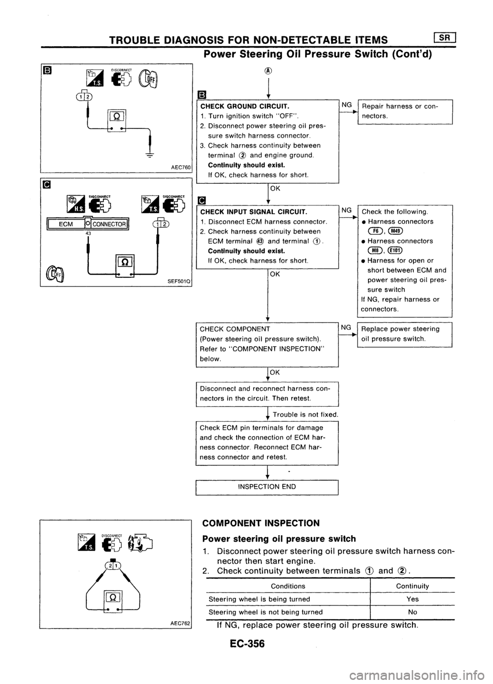
TROUBLEDIAGNOSIS FORNON-DETECTABLE ITEMS
mJ
Power Steering OilPressure Switch
(Cont'd)
~i5
dIb
~i5
II
ECM
~CONNECTORII
43 AEC760
SEF501Q
@
1
CHECK GROUND CIRCUIT. NG
Repair harness orcon-
1. Turn ignition switch"OFF".
--..
nectors.
2. Disconnect powersteering oilpres-
sure switch harness connector.
3. Check harness continuity between
terminal
@
and engine ground.
Continuity shouldexist.
If OK, check harness forshort.
OK
[!J
CHECK INPUTSIGNAL CIRCUIT. NG
Check thefollowing.
1. Disconnect ECMharness connector.
--..
•Harness connectors
2. Check harness continuity between
CID,@
ECM terminal
@
and terminal
CD.
•
Harness connectors
Continuity shouldexist.
@,@D
If OK, check harness forshort. •
Harness foropen or
OK short
between ECMand
power steering oilpres-
sure switch
If NG, repair harness or
connectors.
Power steering oilpressure switch
1. Disconnect powersteering oilpressure switchharness con-
nector thenstart engine.
2. Check continuity betweenterminals
CD
and
@.
~
to
ID
~
CHECK
COMPONENT
(Power steering oilpressure switch).
Refer to"COMPONENT INSPECTION"
below.
OK
Disconnect andreconnect harnesscon-
nectors inthe circuit. Thenretest.
Trouble isnot fixed.
Check ECMpinterminals fordamage
and check theconnection ofECM har-
ness connector. ReconnectECMhar-
ness connector andretest.
INSPECTION END
COMPONENT INSPECTION
Conditions
Steering wheelisbeing turned
Steering wheelisnot being turned NG
Replace powersteering
oil pressure switch.
Continuity
Yes
No
AEC762
IfNG, replace powersteering oilpressure switch.
EC-356
Page 1199 of 1701
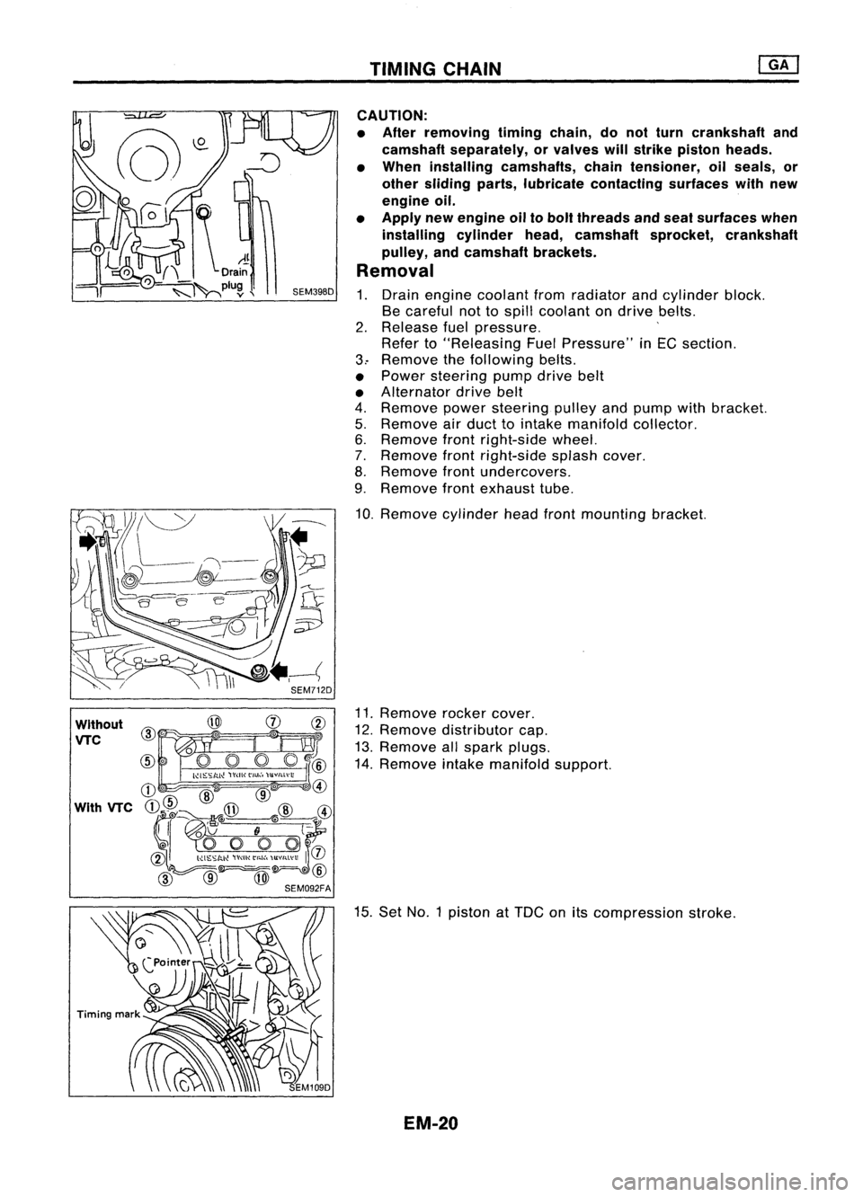
TIMINGCHAIN
Without
VTC
CAUTION:
• After removing timingchain,donot turn crankshaft and
camshaft separately, orvalves willstrike piston heads.
• When installing camshafts, chaintensioner, oilseals, or
other sliding parts,lubricate contacting surfaceswithnew
engine oil.
• Apply newengine oiltobolt threads andseat surfaces when
installing cylinderhead,camshaft sprocket,crankshaft
pulley, andcamshaft brackets.
Removal
1. Drain engine coolant fromradiator andcylinder block.
Be careful nottospill coolant ondrive belts.
2. Release fuelpressure. '
Refer to"Releasing FuelPressure" inEG section.
3.. Remove thefollowing belts.
• Power steering pumpdrivebelt
• Alternator drivebelt
4. Remove powersteering pulleyandpump withbracket.
5. Remove airduct tointake manifold collector.
6. Remove frontright-side wheel.
7. Remove frontright-side splashcover.
8. Remove frontundercovers.
9. Remove frontexhaust tube.
10. Remove cylinderheadfrontmounting bracket.
11. Remove rockercover.
12. Remove distributor cap.
13. Remove allspark plugs.
14. Remove intakemanifold support.
15. Set NO.1 piston at
TOG
onitscompression stroke.
EM-20