1995 NISSAN ALMERA N15 steering wheel
[x] Cancel search: steering wheelPage 711 of 1701
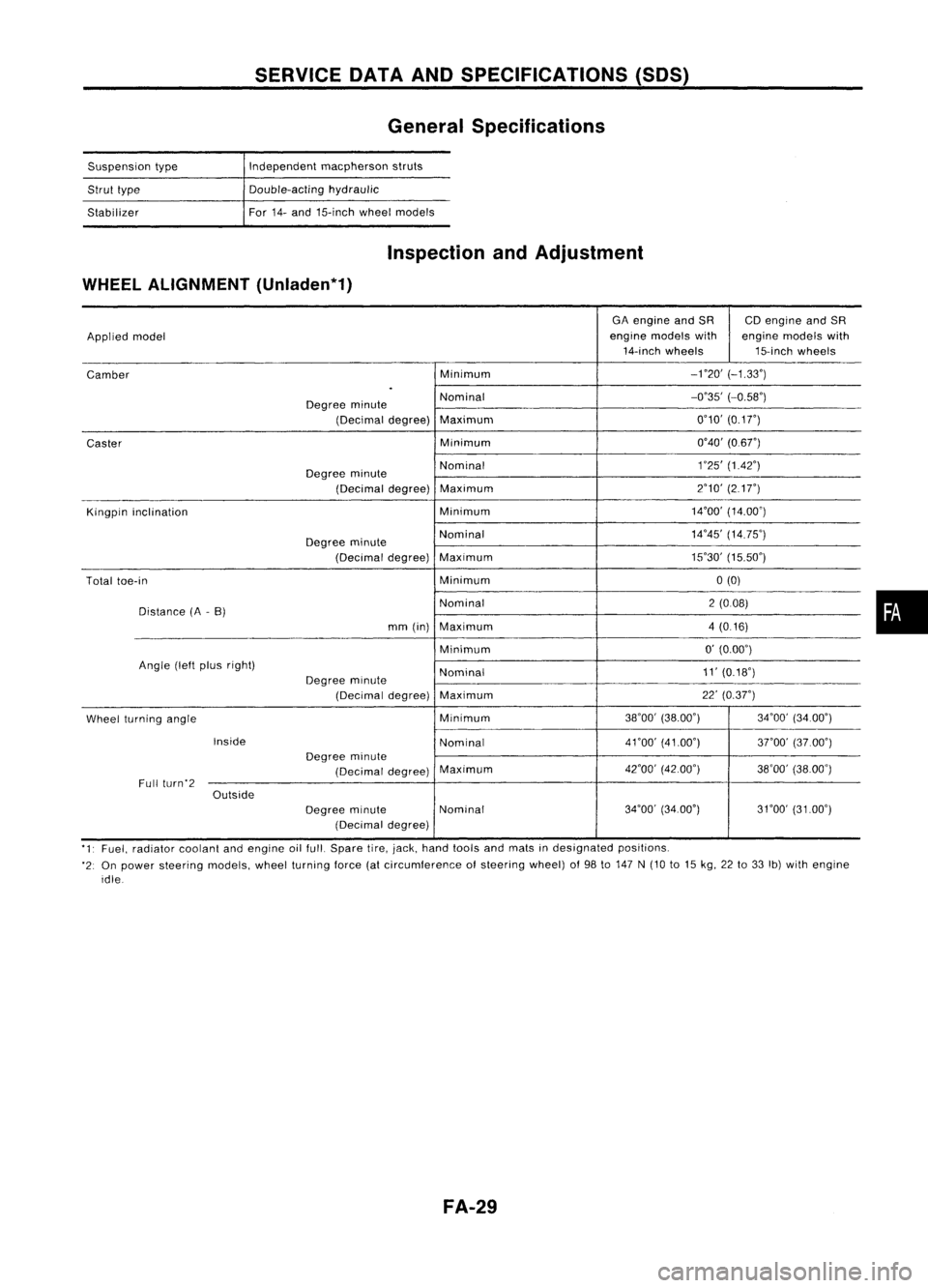
SERVICEDATAANDSPECIFICATIONS (50S)
General Specifications
Suspension type
Strut type
Stabilizer Independent
macpherson struts
Double-acting hydraulic
For 14-and 15-inch wheelmodels
Inspection andAdjustment
WHEEL ALIGNMENT (Unladen*1)
GAengine andSR CDengine andSR
Applied model engine
models with enginemodels with
14-inch wheels 15-inchwheels
Camber Minimum
-no'
(-1.33')
.
Degree minute Nominal
-0'35'
(-0.58')
(Decimal degree)Maximum 0'10'
(0.1
r)
Caster Minimum
0'40'(0.6r)
Degree minute Nominal
1
'25' (1.42')
(Decimal degree)Maximum 2'10'
(217")
Kingpin inclination Minimum14'00'
(14.00')
Degree minute Nominal
14'45'
(14.75')
(Decimal degree)Maximum 15'30'
(15.50')
Total toe-in Minimum0(0)
Distance (A-B) Nominal
2(008)
mm (in) Maximum 4(0.16)
Minimum 0'
(0.00')
Angle (leftplus right)
Nominal 11'
(0.18')
Degree minute
(Decimal degree)Maximum 22'
(0.37")
Wheel turning angle Minimum
38'00'
(38.00') 34'00'(34.00')
Inside Nominal4nO'
(41.00')
3rOO'(37.00')
Degree minute
(Decimal degree)Maximum
42'00'
(42.00')
38'00'(38.00')
Full (urn'2
Outside
Degreeminute Nominal 34'00'
(34.00') 31'00'(3100')
(Decimal degree)
'1' Fuel, radiator coolantandengine oilfull. Spare tire,jack, hand tools andmats indesignated positions.
'2: On power steering models,wheelturning force(atcircumference ofsteering wheel)of98 to147 N(10 to15 kg, 22to33 Ib)with engine
idle
FA-29
•
Page 726 of 1701
PRECAUTIONSANDPREPARATION
Supplemental RestraintSystem(SRS)"AIR
BAG" (DualAirBag System)
The Supplemental RestraintSystem"AirBag", usedalong withaseat belt,helps toreduce therisk or
severity ofinjury tothe driver andfront passenger inafrontal collision. TheSupplemental Restraint
System consists ofair bag modules (locatedinthe center ofthe steering wheelandonthe instrument
panel onthe passenger side),adiagnosis sensorunit,warning lamp,wiring harness andspiral cable.
Information necessarytoservice thesystem safelyisincluded inthe
RSsection
ofthis Service Manual.
WARNING:
• Toavoid rendering theSRS inoperative, whichcouldincrease therisk ofpersonal injuryordeath
in the event ofacollision whichwould resultinair bag inflation, allmaintenance mustbeperformed
by an authorized NISSANdealer. •
• Improper maintenance, includingincorrectremovalandinstallation ofthe SRS, canlead topersonal
injury caused byunintentional activationofthe system.
• Donot use electrical testequipment ~nany circuit related tothe SRS unless instructed tointhis
Service Manual. SRSwiring harnesses arecovered withyellow insulation eitherjustbefore the
harness connectors orfor the complete harness,foreasy identification.
Supplemental RestraintSystem(SRS)"AIR
BAG" (Single AirBag System)
The Supplemental RestraintSystem"AirBag", usedalong withaseat belt, helps toreduce therisk or
severity ofinjury tothe driver inafrontal collision. TheSupplemental RestraintSystemconsists ofan
air bag module (located inthe center ofthe steering wheel),adiagnosis sensorunit,warning lamp,
wiring harness andspiral cable. Information necessarytoservice thesystem safelyisincluded inthe
RS section
ofthis Service Manual.
WARNING: • Toavoid rendering theSRS inoperative, whichcouldincrease therisk ofpersonal injuryordeath
in the event ofacollision whichwould resultinair bag inflation, allmaintenance mustbeperformed
by an authorized NISSANdealer.
• Improper maintenance, includingincorrectremovalandinstallation ofthe SRS, canlead topersonal
injury caused byunintentional activationofthe system.
• Donot use electrical testequipment onany circuit related tothe SRS unless instructed tointhis
Service Manual.
EC-7
Page 774 of 1701
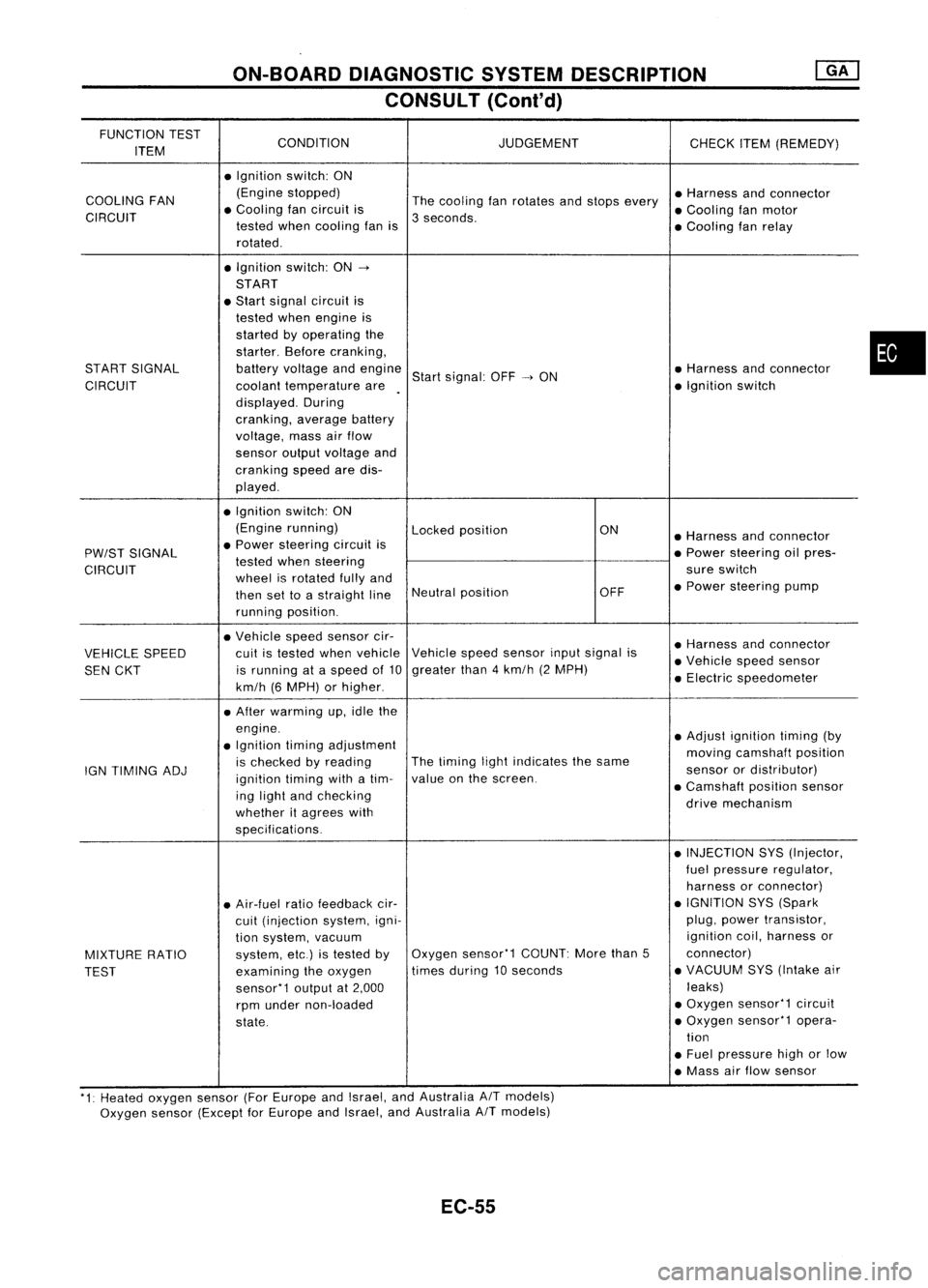
ON-BOARDDIAGNOSTIC SYSTEMDESCRIPTION
CONSULT (Conl'd)
FUNCTION TEST
CONDITION JUDGEMENT
ITEM CHECK
ITEM(REMEDY)
• Ignition switch:ON
COOLING FAN (Engine
stopped)
Thecooling fanrotates andstops every •
Harness andconnector
CIRCUIT •
Cooling fancircuit is
3seconds. •
Cooling fanmotor
tested whencooling fanis
•Cooling fanrelay
rotated .
• Ignition switch:ON-.
START
• Start signal circuit is
tested whenengine is
started byoperating the
starter. Beforecranking,
START SIGNAL batteryvoltage andengine
Startsignal: OFF-.ON •
Harness andconnector
CIRCUIT coolanttemperature are •
Ignition switch
displayed. During
cranking, averagebattery
voltage, massairflow
sensor outputvoltage and
cranking speedaredis-
played .
• Ignition switch:ON
(Engine running)
Lockedposition ON
•Harness andconnector
PW/ST SIGNAL •
Power steering circuitis
•Power steering oilpres-
tested whensteering
CIRCUIT wheelisrotated fullyand sure
switch
then settoastraight lineNeutral
position OFF•
Power steering pump
running position.
• Vehicle speedsensor cir-
•Harness andconnector
VEHICLE SPEED cuit
istested whenvehicle Vehicle
speedsensor inputsignal is
•Vehicle speedsensor
SEN CKT is
running ataspeed of10 greater
than4km/h (2MPH)
•Electric speedometer
km/h (6MPH) orhigher .
• After warming up,idle the
engine. •Adjust ignition timing(by
• Ignition timingadjustment
movingcamshaft position
IGN TIMING ADJ is
checked byreading The
timing lightindicates thesame
sensorordistributor)
ignition timingwithatim- value
onthe screen.
•Camshaft positionsensor
ing light andchecking
drivemechanism
whether itagrees with
specifications.
•INJECTION SYS(Injector,
fuel pressure regulator,
harness orconnector)
• Air-fuel ratiofeedback cir- •
IGNITION SYS(Spark
cuit (injection system,igni- plug,
power transistor,
tion system, vacuum ignition
coil,harness or
MIXTURE RATIO system,
etc.)istested byOxygen
sensor'1 COUNT:Morethan5 connector)
TEST examining
theoxygen times
during 10seconds •
VACUUM SYS(Intake air
sensor'1 outputat2,000 leaks)
rpm under non-loaded •
Oxygen sensor'1 circuit
state. •
Oxygen sensor'1 opera-
tion
• Fuel pressure highorlow
• Mass airflow sensor
'1: Heated oxygen sensor(ForEurope andIsrael, andAustralia AITmodels)
Oxygen sensor(Except forEurope andIsrael, andAustralia
A/T
models)
EC-55
•
Page 784 of 1701
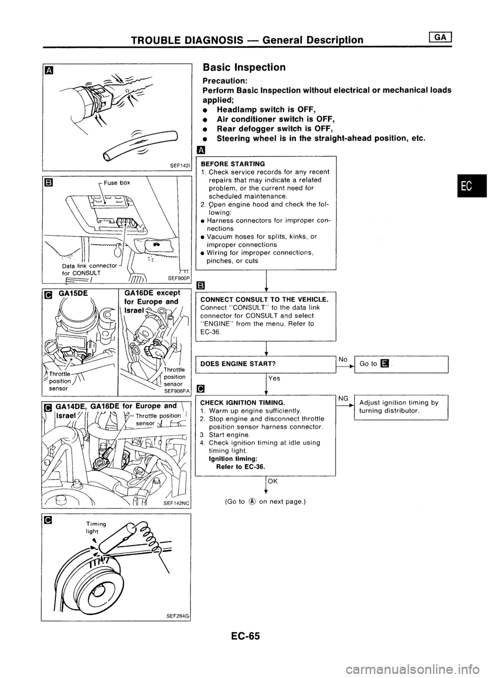
TROUBLEDIAGNOSIS -General Description
Goto
(J.
Adjust ignition timingby
turning distributor.
No
NG
(Go to
@
onnext page.)
OK
CONNECT
CONSULTTOTHE VEHICLE.
Connect "CONSULT" tothe data link
connector forCONSULT andselect
"ENGINE" fromthemenu. Referto
EC-36
DOES ENGINE START?
BEFORE
STARTING
1. Check service records forany recent
repairs thatmay indicate arelated •
problem, orthe current needfor
scheduled maintenance.
2. 9pen engine hoodandcheck thefol.
lowing:
• Harness connectors forimproper con-
nections
• Vacuum hosesforsplits, kinks,or
improper connections
• Wiring forimproper connections,
pinches, orcuts
CHECK IGNITION TIMING.
1. Warm upengine sufficiently.
2. Stop engine anddisconnect throttle
position sensorharness connector.
3. Start engine.
4. Check ignition timingatidle using
timing light.
Ignition liming:
Refer toEC-36.
Basic
Inspection
Precaution:
Perform BasicInspection withoutelectrical or
mechanical loads
applied;
• Headlamp switchisOFF,
• Air conditioner switchisOFF,
• Rear defogger switchisOFF,
• Steering wheelisin the straight-ahead position,etc.
m
\\
~
~ SEF1421
~use box
~-~
vll-JI-
Datalinkconnector~'
EC-65
Page 794 of 1701
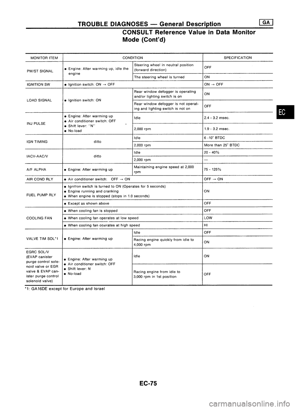
TROUBLEDIAGNOSES -General Description @KJ
CONSULT Reference ValueinData Monitor
Mode (Cont'd)
MONITOR ITEM CONDITION
SPECIFICATION
Steering wheelinneutral position
OFF
PW/ST SIGNAL •
Engine: Afterwarming up.idle the
(forward direction)
engine Thesteering wheelisturned ON
IGNITION SW •
Ignition switch:ON
-->
OFF ON
-->
OFF
Rear window defogger isoperating
ON
and/or lighting switchison
LOAD SIGNAL •
Ignition switch:ON
Rearwindow defogger isnot operat-
OFF
ing and lighting switchisnot on
• Engine: Afterwarming up
Idle 2.4
-3.2 msec.
INJ PULSE •
Air conditioner switch:OFF
• Shift lever: "N"
.
• No-load 2.000
rpm 1.9
-3.2 msec.
Idle 6
_10' BTDC
IGN TIMING ditto
2.000rpm More
than25'BTDC
Idle 20-40%
IACV-AACIV ditto
2.000rpm
-
A/F ALPHA •
Engine: Afterwarming up Maintaining
enginespeedat2.000
75-125%
rpm
AIR COND RLY •
Air conditioner switch:OFF
-->
ON OFF
-->
ON
• Ignition switchisturned toON (Operates for5seconds)
• Engine running andcranking ON
FUEL PUMP RLY
•When engine isstopped (stopsin1.0 seconds)
• Except asshown above OFF
• When cooling fanisstopped OFF
COOLING FAN •
When cooling fanoperates atlow speed LOW
• When cooling fano!Jerates athigh speed HI
Idle OFF
VALVE TIMSOL'1 •Engine: Afterwarming up
Racingenginequickly fromidleto
4.000 rpm ON
EGRC SOLIV
(EVAP canister Idle
ON
purge control sole-•
Engine: Afterwarming up
• Air conditioner switch:OFF
noid valve orEGR
•Shift lever: N
valve
&
EVAP can-
•No-load Racing
enginefromidleto
ister purge control
3.000rpmin1st position OFF
solenoid valve)
*1: GA16DE exceptforEurope andIsrael
EC-75
•
Page 799 of 1701
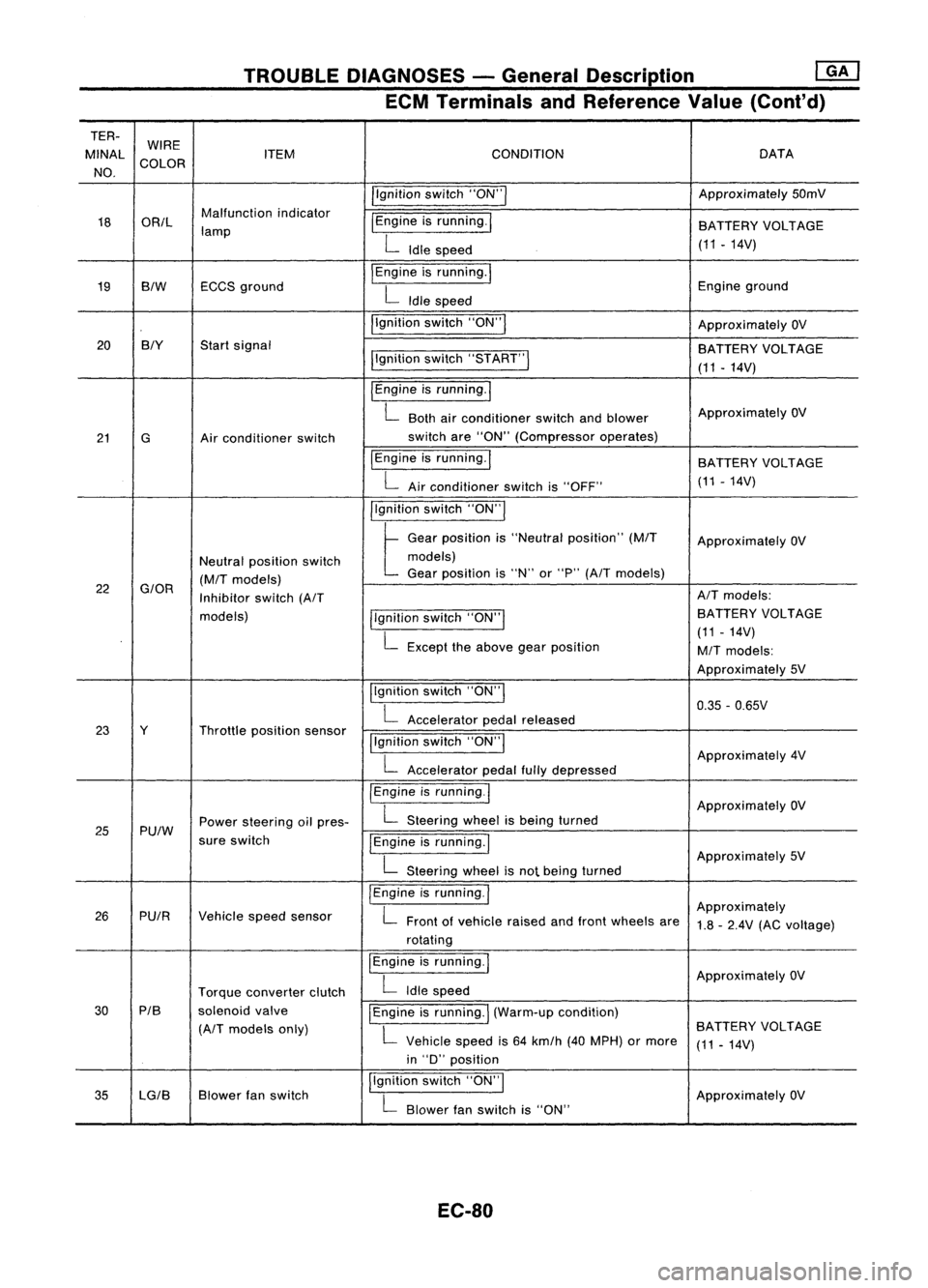
TROUBLEDIAGNOSES -General Description ~
ECM Terminals andReference Value(Cont'd)
TER- WIRE
MINAl ITEM CONDITION DATA
NO. COLOR
/'gnitionswitch"ON'" Approximately
50mV
18 OR/l Malfunction
indicator
I
Engine isrunning.
I
lamp BATTERY
VOLTAGE
L
Idle speed (11.14V)
19 BIW ECCS
ground
I
Engine isrunning.
I
Engineground
L
Idle speed
I'gnition switch"ON"
I
ApproximatelyOV
20 BIY
Startsignal
BATTERYVOLTAGE
I'gnition switch"5TART"
I
(11-14V)
I
Engine isrunning.
I
L
Both airconditioner switchandblower Approximately
OV
21 G Airconditioner switch switch
are"ON" (Compressor operates)
IEngine isrunning.
I
BATTERYVOLTAGE
L
Airconditioner switchis"OFF" (11
-14V)
I'gnition switch"ON'"
t
Ge.,
po,"'on "
"Ne"".1
po,ltlon"
(MIT
Approximately OV
Neutral position switch models)
(M/T
models) Gear
position is"N" or"P"
(A/T
models)
22
G/OR
Inhibitorswitch
(A/T AIT
models:
models) llgnitionswitch"ON'" BATTERY
VOLTAGE
L
Except theabove gearposition (11
-14V)
M/T
models:
Approximately 5V
Ilgnition switch"ON"
I
0.35-0.65V
L
Accelerator pedalreleased
23 Y Throttleposition sensor
!'gnitionswitch"ON"
I
L
Accelerator pedalfullydepressed Approximately
4V
/Engine isrunning.1
ApproximatelyOV
25 Pu/W Power
steering oilpres-
L
Steering wheelisbeing turned
sure switch
IEngineisrunning.1
L
Steering wheelisnot being turned Approximately
5V
I
Engine isrunning.
I
Approximately
26 PUIR Vehiclespeedsensor
L
Front ofvehicle raisedandfront wheels are
1.8-2.4V (ACvoltage)
rotating
I
Engine isrunning.
I
ApproximatelyOV
Torque converter clutch
L
Idle speed
30 PIB
solenoidvalve
I
Engine isrunning.
I
(Warm-up condition)
(A/T
models only)
L
Vehicle speedis64 km/h (40MPH) ormore BATTERY
VOLTAGE
(11-14V)
in "D" position
35 lG/B Blower
fanswitch I,gnition
switch"ON",
ApproximatelyOV
L
Blower fanswitch is"ON"
EC-80
Page 804 of 1701
![NISSAN ALMERA N15 1995 Service Manual TROUBLEDIAGNOSES -General Description @K]
ECM Terminals andReference Value(Conl'd)
TERMINAL WIRE
NO. COLOR ITEM
CONDITION
DATA
Ilgnition switch"ON"I
ApproximatelyOV
34 BIY Startsignal
pgn NISSAN ALMERA N15 1995 Service Manual TROUBLEDIAGNOSES -General Description @K]
ECM Terminals andReference Value(Conl'd)
TERMINAL WIRE
NO. COLOR ITEM
CONDITION
DATA
Ilgnition switch"ON"I
ApproximatelyOV
34 BIY Startsignal
pgn](/manual-img/5/57349/w960_57349-803.png)
TROUBLEDIAGNOSES -General Description @K]
ECM Terminals andReference Value(Conl'd)
TERMINAL WIRE
NO. COLOR ITEM
CONDITION
DATA
Ilgnition switch"ON"I
ApproximatelyOV
34 BIY Startsignal
pgnitionswitch"START"I BATTERY
VOLTAGE
(11 -14V)
pgnition switch"ON"I
t
"N" or"P" position
(A/T)
OV
Neutral position
(M/T)
Neutral position switchl For
Europe andIsrael
35
G/OR
Approximately5V
Inhibitor switch
llgnitionswitch"ON"1
ExceptforEurope and
. L
Except theabove gearposition Israel
BATTERY VOLTAGE
(11 -14V)
Ilgnition switch"OFF"!
OV
36 B/R Ignition
switch(Except
for Europe)
!Ignitionswitch"ON"I BA
TTERY VOLTAGE
(11 •14V)
37 P/L Throttle
position sensor
Ilgnitionswitch"ON"I
Approximately5V
power supply
38
W/R
Powersupply forECM Ilgnition switch"ON"I BA
TTERY VOLTAGE
47 (11
-14V)
IEngine isrunning.1
L
Both airconditioner switchandblower Approximately
OV
41 Gor GY Air
conditioner switch fan
switch are"ON".
!Engine isrunning.1
BATTERYVOLTAGE
L
Airconditioner switchis"OFF". (11
-14V)
IEngine isrunning.!
OV
PU/W Power
steering oilpres-
L
Steering wheelisbeing turned.
43 sureswitch
IEngineisrunning.1
L
Steering wheelisnot being turned. Approximately
5V
jlgnition switch"OFF"I OV
Ignition switch
44 B/R
(ForEurope) BA
TTERY VOLTAGE
pgnition switch"ON"I
(11-14V)
IEngine isrunning.1
Thermo controlamp.
L
Both airconditioner switchandblower fanApproximately
OV
44 R/L (Except
forEurope and switch
are"ON".
Israel) IEngineisrunning.1
BATTERYVOLTAGE
L
Airconditioner switchis"OFF". (11
-14V)
IEngine isrunning.1
ApproximatelyOV
L
Blower fanswitch is"ON".
45 LG/B
or
Blower fanswitch
G/Y
IEngineisrunning.!
L
Blower fanswitch is"OFF". Approximately
5V
EC-85
•
Page 890 of 1701

•
INSPECTION END
OK
The
power steering oilpressure switchisattached tothe power
steering high-pressure tubeanddetects apower steering load.
When apower steering loadisdetected,
it
signals theECM. The
ECM adjusts theIACV-AAC valvetoincrease theidle speed and
adjust forthe increased load.
INSPECTION START
OR
1. Start engine.
2. Check voltage between ECM
terminal
@
or
@
and ground.
Voltage: When steering wheelis
turned quickly.
Approximately OV
Except above
Approximately 5V
NG
DIAGNOSTIC
PROCEDURE
CHECK OVERALL FUNCTION.
fiii\
1.Turn ignition switch"ON".
~ 2.Perform "PW/STSIGNAL
CIRCUIT" in"FUNCTION
TEST" modewithCONSULT.
OR
(F.i\
1.Start engine.
~ 2.Check "PW/ST SIGNAL" in
"DATA MONITOR" modewith
CONSULT.
Steering isin neutral
position: OFF
Steering isturned:
ON
SEF591I
SEF235R
MEF023E
Power
steering oil___
pressure switch
-
~
to
TROUBLE
DIAGNOSIS FORNON-DETECTABLE ITEMS
@[]
Power Steering OilPressure Switch(Cont'd)
COMPONENT DESCRIPTION
RECORD
NEXT
II
START
•
PW/ST SIGNAL CIRCUIT.
HOLD STEERING WHEEL
IN AFULL
LOCKED
POSITION
THEN
TOUCH START
* MONITOR *NO FAIL
0
PW/ST SIGNAL OFF
@):
ForAustralia
@:
Except forAustralia
~i)~
II
ECM
Ef
CONNECTOR
II
43 25
EC-171