1995 NISSAN ALMERA N15 steering wheel
[x] Cancel search: steering wheelPage 1660 of 1701
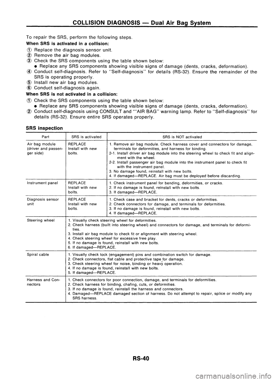
COLLISIONDIAGNOSIS -Dual AirBag System
To repair theSRS, perform thefollowing steps.
When SRSisactivated inacollision:
CD
Replace thediagnosis sensorunit.
@ Remove
theairbag modules.
@
Check theSRS components usingthetable shown below:
• Replace anySRS components showing
visible
signsofdamage (dents,cracks, deformation).
@
Conduct self-diagnosis. Referto"Self-diagnosis" fordetails (RS-32). Ensuretheremainder ofthe
SRS isoperating properly.
@
Conduct self-diagnosis again.
When SRSisnot activated inacollision:
CD
Check theSRS components usingthetable shown below:
• Replace anySRS components showingvisiblesignsofdamage (dents,cracks, deformation).
@
Conduct self-diagnosis usingCONSULT and"'AIR BAG" warning lamp.Referto"Self-diagnosis" for
details (RS-32). EnsureentireSRSoperates properly.
SRS inspection
Part SRSisactivated
SRSisNOT activated
Air bag module REPLACE
1.Remove airbag module. Checkharness coverandconnectors fordamage,
(driver andpassen-
Installwithnew terminalsfordeformities, andharness forbinding.
ger side) bolts.
2-1.Install driverairbag module intothesteering wheeltocheck fitand align-
ment withthewheel.
2-2. Install passenger airbag module intotheinstrument paneltocheck fit
with theinstrument panel.
3. No damage found,reinstall withnewbolts.
4. Ifdamaged-REPLACE. Airbag must bedeployed beforediscarding.
Instrument panel
REPLACE 1.Check instrument panelforbending, deformities, orcracks.
Install withnew
2.Ifno damage isfound, reinstall withnewbolts.
bolts. 3.Ifdamaged-REPLACE.
Diagnosis sensor REPLACE
1.Check caseandbracket fordents, cracks ordeformities.
unit Installwithnew
2.Check connectors fordamage, andterminals fordeformities.
bolts. 3.Ifno damage isfound, reinstall withnewbolts.
4. Ifdamaged-REPLACE.
Steering wheel
1.Visually checksteering wheelfordeformities.
2. Check harness (builtintosteering wheel)andconnectors fordamage, andterminals fordeformi-
ties.
3. Install airbag module tocheck fitor alignment withsteering wheel.
4. Check steering wheelforexcessive freeplay.
5. Ifno damage isfound, reinstall withnewbolts.
6. Ifdamaged-REPLACE.
Spiral cable
1.Visually checklock(engagement) pinsandcombination switchfordamage.
2. Check connectors, flatcable andprotective tapefordamage.
3. Check steering wheelfornoise, binding orheavy operation.
4. Ifno damage isfound, reinstall withnew bolts.
5. Ifdamaged-REPLACE.
Harness andCon-
1.Check connectors forpoor connection, damage,andterminals fordeformities.
nectors 2.Check harness forbinding, chafing,cuts,ordeformities.
3. Ifno damage isfound, reinstall theharness andconnectors.
4. Damaged-REPLACE damagedsectionofharness. Donot attempt torepair, spliceormodify any
SRS harness.
RS-40
Page 1664 of 1701
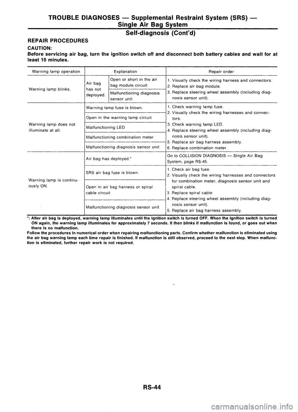
TROUBLEDIAGNOSES -Supplemental RestraintSystem(SRS)
Single AirBag System
Self-diagnosis (Cont'd)
REPAIR PROCEDURES
CAUTION:
Before servicing airbag, turntheignition switchoffand disconnect bothbattery cablesandwail forat
least 10minutes.
Warning lampoperation Explanation
Repairorder
Open orshort inthe air
1.Visually checkthewiring harness andconnectors.
Air bag
bagmodule circuit.
2.Replace airbag module.
Warning lampblinks. hasnot
3.Replace steering wheelassembly (including diag-
deployed. Malfunctioning
diagnosis
sensor unit nos
issensor unit).
Warning lampfuseisblown. 1.
Check warning lampfuse.
2. Visually checkthewiring harnesses andconnec-
Open inthe warning lampcircuit
tors.
Warning lampdoes not
Malfunctioning LED 3.
Check warning lampLED.
illuminate atall. 4.Replace steering wheelassembly (including diag-
Malfunctioning combinationmeter nos
issensor unit).
5. Replace airbag harness assembly.
Malfunctioning diagnosissensorunit
6.Replace combination meter.
Air bag hasdeployed: Go
toCOLLISION DIAGNOSIS -Single AirBag
System, pageRS-45.
1. Check airbag fuse.
SRS airbag fuse isblown.
2.
Visually checkthewiring harnesses andconnectors
Warning lampiscontinu-
forcombination meter,diagnosis sensorunitand
ously ON.
Openinair bag harness orspiral
spiralcable.
cable circuit 3.
Replace spiralcable.
4. Replace steeringwheelassembly (including diag-
Malfunctioning diagnosissensorunit nosis
sensor unit).
5. Replace airbag harness assembly.
*;
After airbag isdeployed, warninglampilluminates untiltheignition switchisturned OFF.When theIgnition switchisturned
ON again, Ihewarning lampilluminates forapproximately 7seconds. Itthen blinks ifmalfunction isfound, orgoes outwhen
there isno malfunction.
Follow theprocedures innumerical orderwhenrepairing malfunctioning parts.Confirm whether malfunction iseliminated using
the airbag warning lampeachtimerepair isfinished. Ifmalfunction isstill observed, proceedtothe next step. When malfunc-
tion iseliminated, furtherrepairworkisnot required.
RS-44
Page 1665 of 1701
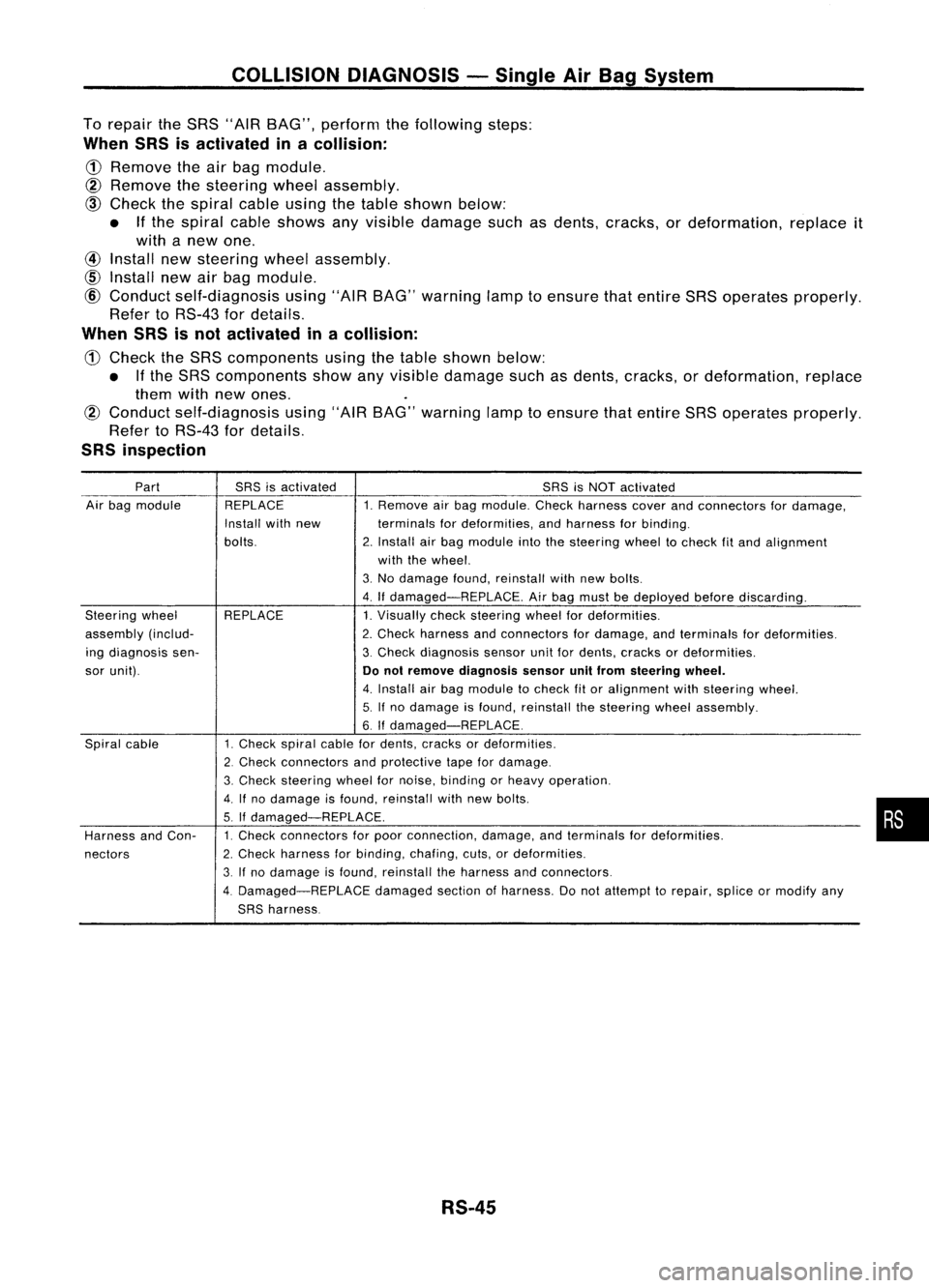
COLLISIONDIAGNOSIS -Single AirBag System
To repair theSRS "AIR BAG", perform thefollowing steps:
When SRSisactivated inacollision:
CD
Remove theairbag module.
@
Remove thesteering wheelassembly.
@)
Check thespiral cableusingthetable shown below:
• Ifthe spiral cableshows anyvisible damage suchasdents, cracks, ordeformation, replaceit
with anew one.
@
Install newsteering wheelassembly.
CID
Install newairbag module.
@
Conduct self-diagnosis using"AIRBAG" warning lamptoensure thatentire SRSoperates properly.
Refer toRS-43 fordetails.
When SRSisnot activated inacollision:
CD
Check theSRS components usingthetable shown below:
• Ifthe SRS components showanyvisible damage suchasdents, cracks, ordeformation, replace
them withnewones.
@
Conduct self-diagnosis using"AIRBAG" warning lamptoensure thatentire SRSoperates properly.
Refer toRS-43 fordetails.
SRS inspection
Part SRSisactivated SRSisNOT activated
Air bag module REPLACE 1.Remove airbag module. Checkharness coverandconnectors fordamage,
Install withnew terminalsfordeformities, andharness forbinding.
bolts. 2.Install airbag module intothesteering wheeltocheck fitand alignment
with thewheel.
3. No damage found,reinstall withnewbolts.
4. Ifdamaged-REPLACE. Airbag must bedeployed beforediscarding.
Steering wheel REPLACE 1.Visually checksteering wheelfordeformities.
assembly (includ- 2.Check harness andconnectors fordamage, andterminals fordeformities.
ing diagnosis sen- 3.Check diagnosis sensorunitfordents, cracks ordeformities.
sor unit).
Donot remove diagnosis sensorunitfrom steering wheel.
4. Install airbag module tocheck fitor alignment withsteering wheel.
5. Ifno damage isfound, reinstall thesteering wheelassembly.
6.
If
damaged-REPLACE.
Spiral cable 1.Check spiralcablefordents, cracks ordeformities.
2. Check connectors andprotective tapefordamage.
3. Check
steering wheelfornoise, binding orheavy operation.
4.
If
no damage isfound, reinstall withnewbolts.
5. If
damaged-REPLACE.
Harness andCon- 1.
Check connectors forpoor connection, damage,andterminals fordeformities.
nectors 2.
Check harness forbinding, chafing,cuts,ordeformities.
3. Ifno damage isfound, reinstall theharness andconnectors.
4. Damaged-REPLACE damagedsectionofharness. Donot attempt torepair, spliceormodify any
SRS harness.
RS-45
•
Page 1667 of 1701
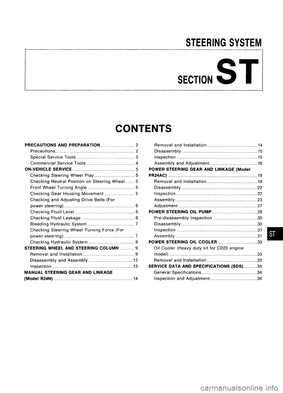
STEERINGSYSTEM
SECTIONST
CONTENTS
PRECAUTIONS ANDPREPARATION 2
Precautions 2
Special Service Tools 3
Commercial ServiceTools 4
ON-VEHICLE SERVICE
5
Checking SteeringWheelPlay 5
Checking NeutralPosition onSteering Wheel 5
Front Wheel Turning Angle 5
Checking GearHousing Movement 5
Checking andAdjusting DriveBelts(For
power steering) 6
Checking FluidLevel 6
Checking FluidLeakage 6
Bleeding Hydraulic System 7
Checking SteeringWheelTurning Force(For
power steering) 7
Checking Hydraulic System 8
STEERING WHEElANDSTEERING COLUMN 9
Removal andInstallation 9
Disassembly andAssembly 12
Inspection 13
MANUAL STEERING GEARANDLINKAGE
(Model R24N) 14
Removal
andInstallation 14
Disassembly 15
Inspection 15
Assembly andAdjustment... 16
POWER STEERING GEARANDLINKAGE (Model
PR24AC) 19
Removal andInstallation 19
Disassembly 22
Inspection 22
Assembly ,.. 23
Adjustment 27
POWER STEERING OILPUMP 29
Pre-disassembly Inspection 30
Disassembly 30
Inspection 31
Assembly 31
POWER STEERING OILCOOLER
33
Oil Cooler (Heavy dutykitfor CD20 engine
model) 33
Removal andInstallation 33
SERVICE DATAANDSPECIFICATIONS
(505)34
General Specifications 34
Inspection andAdjustment 34
•
Page 1668 of 1701
PRECAUTIONSANDPREPARATION
Precautions
SUPPLEMENTAL RESTRAINTSYSTEM(SRS)"AIRBAG"
(Dual AirBag System)
The Supplemental RestraintSystem"AirBag" usedalong withaseat belt,helps toreduce therisk or
severity ofinjury tothe driver andfront passenger inafrontal collision. TheSupplemental Restraint
System consists ofair bag modules (locatedinthe center ofthe steering wheelandonthe instrument
panel onthe passenger side),adiagnosis sensorunit,warning lamp,wiring harness andspiral cable.
Information necessarytoservice thesystem safelyisincluded inthe
RSsection
ofthis Service Manual.
WARNING: • Toavoid rendering theSRS inoperative, whichcouldincrease therisk ofpersonal injuryordeath
in the event ofacollision whichwould resultinair bag inflation, allmaintenance mustbeperformed
by an authorized NISSANdealer.
• Improper maintenance, includingincorrectremovalandinstallation ofthe SRS, canlead topersonal
injury caused byunintentional activationofthe system.
• Donot use electrical testequipment onany circuit related tothe SRS unless instructed tointhis
Service Manual. SRSwiring harnesses arecovered withyellow insulation eitherjustbefore the
harness connectors orfor the complete harness,foreasy identification.
SUPPLEMENTAL RESTRAINTSYSTEM(SRS)"AIRBAG"
(Single AirBag System)
The Supplemental RestraintSystem"AirBag" andused along withaseat belt,helps toreduce therisk
or severity ofinjury tothe driver inafrontal collision. TheSupplemental RestraintSystemconsists of
an air bag module (located inthe center ofthe steering wheel),adiagnosis sensorunit,warning lamp,
wiring harness andspiral cable. Information necessarytoservice thesystem safelyisincluded inthe
RS section
ofthis Service Manual.
WARNING: • Toavoid rendering theSRS inoperative, whichcouldincrease therisk ofpersonal injuryordeath
in the event ofacollision whichwould resultinair bag inflation, allmaintenance mustbeperformed
by an authorized NISSANdealer.
• Improper maintenance, includingincorrectremovalandinstallation ofthe SRS, canlead topersonal
injury caused byunintentional activationofthe system.
• Donot use electrical testequipment onany circuit related tothe SRS unless instructed tointhis
Service Manual.
STEERINGSYSTEM
• Before disassembly, thoroughlycleantheoutside ofthe unit.
• Disassembly shouldbedone inaclean workarea. Itis important toprevent theinternal partsfrom
becoming contaminated bydirt orother foreign matter.
• Place disassembled partsinorder, onaparts rack,fore"asier andproper assembly.
• Use nylon cloths orpaper towels toclean theparts; common shopragscanleave lintthat might
interfere withtheir operation.
• Before inspection orreassembly, carefullycleanallparts withageneral purpose, non-flammable
solvent.
• Before assembly, applyacoat ofrecommended ATF*tohydraulic parts.Vaseline maybeapplied to
O-rings andseals. Donot use any grease.
• Replace allgaskets, sealsandO-rings. Avoiddamaging O-rings,sealsandgaskets duringinstalla-
tion. Perform functional testswhenever designated.
*:
Automatic transmission fluid
ST-2
Page 1669 of 1701
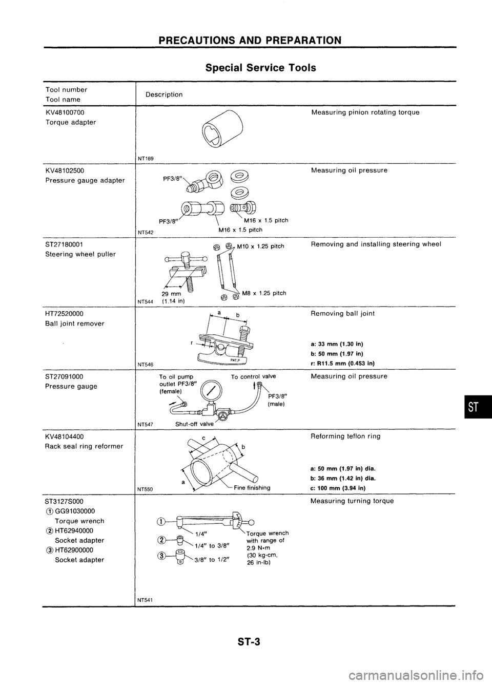
Toolnumber
Tool name PRECAUTIONS
ANDPREPARATION
Special Service Tools
Description
KV481 00700
Torque adapter
KV481 02500
Pressure gaugeadapter NT169
NT542 PF3/B"~
@
@
PF3/B"~ ~x1.5 pitch
M16 x1.5 pitch Measuring
pinionrotating torque
Measuring oilpressure
ST27180001
Steering wheelpuller
NT544(1.14
in)
@Q'O
,'25 0;'0'
@ @
MB
x1.25 pitch Removing
andinstalling steeringwheel
HT72520000
Ball joint remover
ST27091000 Pressure gauge
KV481 04400
Rack sealringreformer
ST3127S000
G)
GG91030000
Torque wrench
@ HT62940000
Socket adapter
@
HT62900000
Socket adapter NT546
NT547
NT550
NT541 To
control valve
Shut-off valve
~ 1/4"~rque wrench
~ withrange of
1/4"
to
3/B" 2.9
N.m
~ ""(30kg-em,
'V
'td"
3/B
to
1/2
26
in-Ib)
ST-3 Removing
balljoint
a:
33
mm
(1.30
in)
b: 50
mm
(1.97
in)
r:
R11.5
mm
(0.453
in)
Measuring oilpressure
Reforming teflonring
a: 50 mm (1.97 in)dia.
b: 36 mm (1.42 in)dia.
c:
100
mm
(3.94
in)
Measuring turningtorque
•
Page 1671 of 1701
ON-VEHICLESERVICE
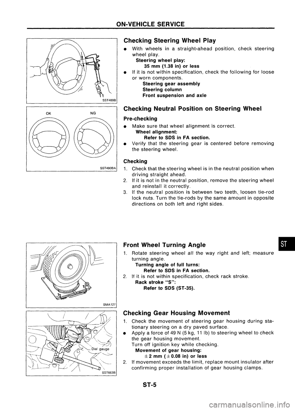
Checking SteeringWheelPlay
• With wheels inastraight-ahead position,checksteering
wheel play.
Steering wheelplay:
35 mm (1.38 in)orless
• Ifit is not within specification, checkthefollowing forloose
or worn components.
Steering gearassembly
Steering column
Front suspension andaxle
SST489B
OK
NGChecking
NeutralPosition onSteering Wheel
Pre-checking
• Make surethatwheel alignment iscorrect.
Wheel alignment:
Refer toSOS inFA section.
• Verify thatthesteering geariscentered beforeremoving
the steering wheel.
Checking
SST490BA
1.Check thatthesteering wheelisin the neutral position when
driving straight ahead.
2. Ifit is not inthe neutral position, removethesteering wheel
and reinstall itcorrectly.
3. Ifthe neutral position isbetween twoteeth,. loosen tie-rod
lock nuts. Turnthetie-rods bythe same amount inopposite
directions onboth leftand right sides.
Front Wheel Turning Angle •
1. Rotate steering wheelallthe way right andleft;measure
turning angle.
Turning angleoffull turns:
Refer toSOS inFA section.
2. Ifit is not within specification, checkrackstroke.
Rack stroke
"S":
Refer toSOS (ST-35).
SMA127 Checking GearHousing Movement
1. Check themovement ofsteering gearhousing duringsta-
tionary steering onadry paved surface.
• Apply aforce of49 N(5 kg, 11Ib) tosteering wheeltocheck
the gear housing movement.
Turn offignition keywhile checking.
Movement ofgear housing:
:I:
2 mm
(:I:
0.08 in)orless
2. Ifmovement exceedsthelimit, replace mountinsulator after
confirming properinstallation ofgear housing clamps.
ST-5
Page 1672 of 1701
ON-VEHICLESERVICE
Checking andAdjusting DriveBelts(Forpower
steering)
Refer to"Checking DriveBelts" for"ENGINE MAINTENANCE"
in MA section.
SST476C
S
r
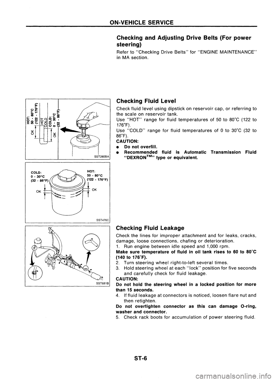
SST681B Checking
Fluidlevel
Check fluidlevel using dipstick onreservoir cap,orreferring to
the scale onreservoir tank.
Use "HOT" rangeforfluid temperatures of50 to80°C (122to
176°F).
Use "COLD" rangeforfluid temperatures of0to 30°C (32to
86°F).
CAUTION:
• Donot overfill.
• Recommended fluidisAutomatic Transmission Fluid
''DEXRON™,, typeorequivalent.
Checking Fluidleakage
Check thelines forimproper attachment andforleaks, cracks,
damage, looseconnections, chafingordeterioration.
1. Run engine between idlespeed and1,000 rpm.
Make suretemperature offluid inoil tank rises to60 to80°C
(140 to176°F).
2. Turn steering wheelright-to-Ieft severaltimes.
3. Hold steering wheelateach "lock" position forfive seconds
and carefully checkforfluid leakage.
CAUTION:
Do not hold thesteering wheelinalocked position formore
than 15seconds.
4. Iffluid leakage atconnectors isnoticed, loosenflarenutand
then retighten.
Do not overtighten connectorasthis candamage O-ring,
washer andconnector.
5. Check rackboots foraccumulation ofpower steering fluid.
ST-6