1995 NISSAN ALMERA N15 srs wiring
[x] Cancel search: srs wiringPage 1403 of 1701
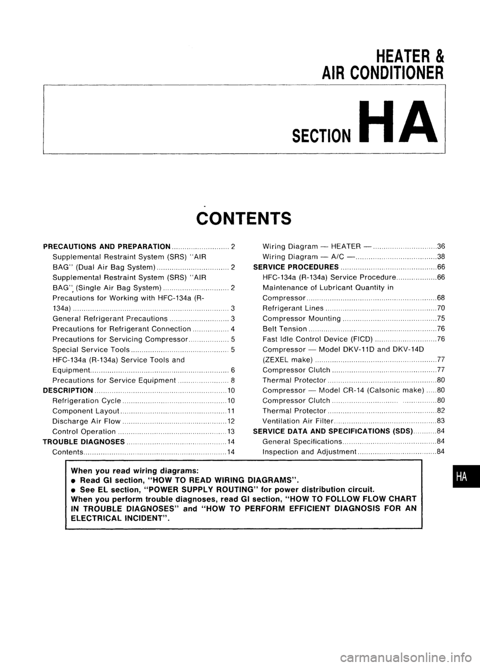
HEATER
&
AIR CONDITIONER
SECTION
HA
CONTENTS
When youread wiring diagrams:
• Read GIsection, "HOWTOREAD WIRING DIAGRAMS" .
• See ELsection, "POWER SUPPLYROUTING" forpower distribution circuit.
When youperform troublediagnoses, readGIsection, "HOWTOFOLLOW FLOWCHART
IN TROUBLE DIAGNOSES" and"HOW TOPERFORM EFFICIENT DIAGNOSIS FORAN
ELECTRICAL INCIDENT".
PRECAUTIONS
ANDPREPARATION 2
Supplemental RestraintSystem(SRS)"AIR
BAG" (DualAirBag System) 2
Supplemental RestraintSystem(SRS)"AIR
BAG", (Single AirBag System) 2
Precautions forWorking withHFC-134a (R-
134a) 3
General Refrigerant Precautions 3
Precautions forRefrigerant Connection 4
Precautions forServici ngCompressor. ..5
Special Service Tools 5
HFC-134a (R-134a)ServiceToolsand
Equipment. 6
Precautions forService Equipment 8
DESCRIPTION 10
Refrigeration Cycle .10
Component Layout 11
Discharge AirFlow 12
Control Operation 13
TROUBLE DIAGNOSES 14
Contents 14Wiring
Diagram -HEATER - 36
Wiring Diagram -
AIC - 38
SERVICE PROCEDURES 66
HFC-134a (R-134a)ServiceProcedure 66
Maintenance ofLubricant Quantityin
Compressor 68
Refrigerant Lines 70
Compressor Mounting 75
Belt Tension 76
Fast IdleControl Device(FICO) 76
Compressor -Model DKV-11D andDKV-14D
(ZEXEL make) 77
Compressor Clutch 77
Thermal Protector 80
Compressor -Model CR-14 (Calsonic make)80
Compressor Clutch ..80
Thermal Protector 82
Ventilation AirFilter 83
SERVICE DATAANDSPECIFICATIONS (SDS)84
General Specifications 84
Inspection andAdjustment 84
•
Page 1404 of 1701
PRECAUTIONSANDPREPARATION
Supplemental RestraintSystem(SRS)"AIR
BAG" (DualAirBag System)
The Supplemental RestraintSystem"AirBag" usedalong withaseat belt,helps toreduce therisk or
severity ofinjury tothe driver andfront passenger inafrontal collision. TheSupplemental Restraint
System consists ofair bag modules (locatedinthe center ofthe steering wheelandonthe instrument
panel onthe passenger side),adiagnosis sensorunit,warning lamp,wiring harness andspiral cable.
Information necessarytoservice thesystem safelyisincluded inthe
RSsection
ofthis Service Manual.
WARNING:
• Toavoid rendering theSRS inoperative, whichcouldincrease therisk ofpersonal injuryordeath
in the event ofacollision whichwould resultinair bag inflation, allmaintenance mustbeperformed
by an authorized NISSANdealer.
• Improper maintenance, includingincorrectremovalandinstallation ofthe SRS, canlead topersonal
injury caused byunintentional activationofthe system.
• Donot use electrical testequipment onany circuit related tothe SRS unless instructed tointhis
Service Manual. SRSwiring harnesses arecovered withyellow insulation eitherjustbefore the
harness connectors orfor the complete harness,foreasy identification.
Supplemental RestraintSystem(SRS)"AIR
BAG" (Single AirBag System)
The Supplemental RestraintSystem"AirBag" andused along withaseat belt,helps toreduce therisk
or severity ofinjury tothe driver inafrontal collision. TheSupplemental RestraintSystemconsists of
an air bag module (located inthe center ofthe steering wheel),adiagnosis sensorunit,warning lamp,
wiring harness andspiral cable. Information necessarytoservice thesystem safelyisincluded inthe
RS section
ofthis Service Manual.
WARNING: • Toavoid rendering theSRS inoperative, whichcouldincrease therisk ofpersonal injuryordeath
in the event ofacollision whichwould resultinair bag inflation, allmaintenance mustbeperformed
by anauthorized NISSANdealer.
• Improper maintenance, includingincorrectremovalandinstallation ofthe SRS, canlead topersonal
injury caused byunintentional activationofthe system.
• Donot use electrical testequipment onany circuit related tothe SRS unless instructed tointhis
Service Manual.
HA-2
Page 1489 of 1701
PRECAUTIONSANDPREPARATION
Supplemental RestraintSystem(SRS)"AIR
BAG" (DualAirBag System)
The Supplemental RestraintSystem"AirBag", usedalong withaseat belt,helps toreduce therisk or•
severity ofinjury tothe driver andfront passenger inafrontal collision. TheSupplemental Restraint
i
System consists ofair bag modules (locatedinthe center ofthe steering wheelandonthe instrument
panel onthe passenger side).adiagnosis sensorunit,warning lamp,wiring harness andspiral cable.
Information necessarytoservice thesystem safelyisincluded inthe
RSsection
ofthis Service Manual.
WARNING:
• Toavoid rendering theSRS inoperative, whichcouldincrease therisk ofpersonal injuryordeath
in the event ofacollision whichwould resultinair bag inflation, allmaintenance mustbeperformed
by an authorized NISSANdealer.
• Improper maintenance, includingincorrectremovalandinstallation ofthe SRS, canlead topersonal
injury caused byunintentional activationofthe system.
• Donot use electrical testequipment onany circuit related tothe SRS unless instructed tointhis
Service Manual. SRSwiring harnesses arecovered withyellow insulation eitherjustbefore the
harness connectors orfor the complete harness,foreasy identification.
Supplemental RestraintSystem(SRS)"AIR
BAG" (Single AirBag System)
The Supplemental RestraintSystem"AirBag", usedalong withaseat belt,helps toreduce therisk or
severity ofinjury tothe driver inafrontal collision. TheSupplemental RestraintSystemconsists ofan
air bag module (located inthe center ofthe steering wheel),adiagnosis sensorunit,warning lamp,
wiring harness andspiral cable. Information necessarytoservice thesystem safelyisincluded inthe
RS section
ofthis Service Manual.
WARNING:
• Toavoid rendering theSRS inoperative, whichcouldincrease therisk ofpersonal injuryordeath
in the event ofacollision whichwould resultinair bag inflation, allmaintenance mustbeperformed
by an authorized NISSANdealer.
• Improper maintenance, includingincorrectremovalandinstallation ofthe SRS, canlead topersonal
injury caused byunintentional activationofthe system.
• Donot use electrical testequipment onany circuit related tothe SRS.
MA-3
Page 1621 of 1701
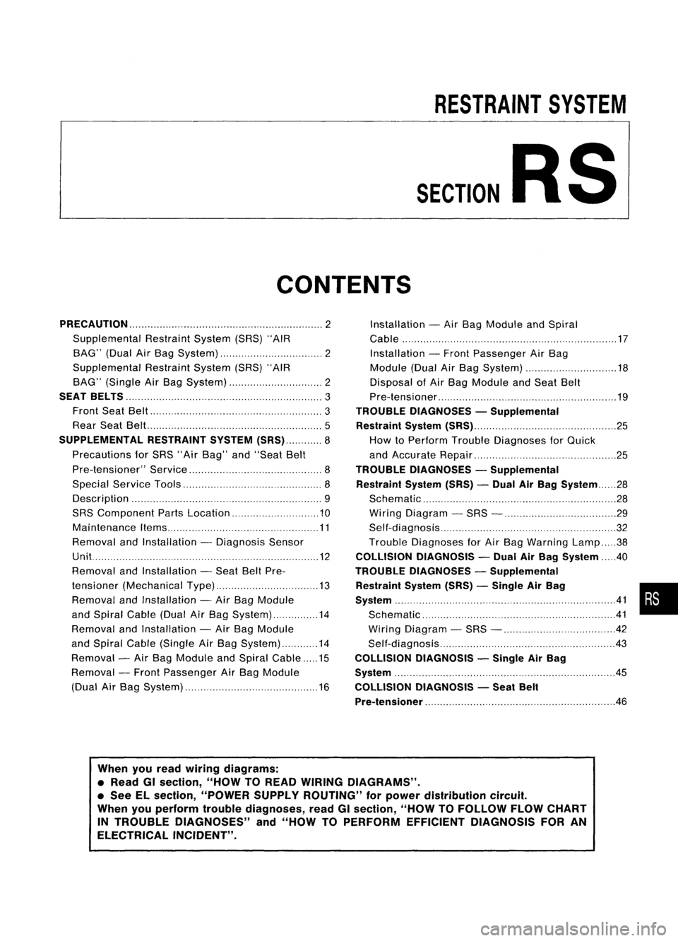
RESTRAINTSYSTEM
SECTION
RS
CONTENTS
PRECAUTION 2
Supplemental RestraintSystem(SRS)"AIR
BAG" (DualAirBag System) 2
Supplemental RestraintSystem(SRS)"AIR
BAG" (Single AirBag System) 2
SEAT BELTS
3
Front SeatBelt 3
Rear SeatBel!. 5
SUPPLEMENTAL RESTRAINTSYSTEM(SRS) 8
Precautions forSRS "AirBag" and"Seat Belt
Pre-tensioner" Service 8
Special Service Tools 8
Description 9
SRS Component PartsLocation 10
Maintenance Items 11
Removal andInstallation -Diagnosis Sensor
Unit. 12
Removal andInstallation -Seat BeltPre-
tensioner (Mechanical Type) 13
Removal andInstallation -Air Bag Module
and Spiral Cable(DualAirBag System) 14
Removal andInstallation -Air Bag Module
and Spiral Cable(Single AirBag System) 14
Removal -Air Bag Module andSpiral Cable 15
Removal -Front Passenger AirBag Module
(Dual AirBag System) 16Installation
-Air Bag Module andSpiral
Cable 17
Installation -Front Passenger AirBag
Module (DualAirBag System) 18
Disposal ofAir Bag Module andSeat Belt
Pre-tensioner 19
TROUBLE DIAGNOSES -Supplemental
Restraint System(SRS) 25
How toPerform TroubleDiagnoses forQuick
and Accurate Repair 25
TROUBLE DIAGNOSES -Supplemental
Restraint System(SRS)-Dual AirBag System 28
Schematic 28
Wiring Diagram -SRS - 29
Self-diagnosis 32
Trouble Diagnoses forAir Bag Warning Lamp38
COLLISION DIAGNOSIS -Dual AirBag System .40
TROUBLE DIAGNOSES -Supplemental
Restraint System(SRS)-Single AirBag •
System 41•
Schematic 41
Wiring Diagram -SRS - 42
Self-diagnosis 43
COLLISION DIAGNOSIS -Single AirBag
System .45
COLLISION DIAGNOSIS -Seat Belt
Pre-tensioner
.46
When youread wiring diagrams:
• Read GIsection, "HOWTOREAD WIRING DIAGRAMS" .
• See ELsection, "POWER SUPPLYROUTING" forpower distribution circuit.
When youperform troublediagnoses, readGIsection, "HOWTOFOLLOW FLOWCHART
IN TROUBLE DIAGNOSES" and"HOW TOPERFORM EFFICIENT DIAGNOSIS FORAN
ELECTRICAL INCIDENT".
Page 1622 of 1701
PRECAUTION
Supplemental RestraintSystem(SRS)"AIR
BAG" (DualAirBag System)
The Supplemental RestraintSystem"AirBag", usedalong withaseat belt, helps toreduce therisk or
severity ofinjury tothe driver andfront passenger inafrontal collision. TheSupplemental Restraint
System consists ofair bag modules (locatedinthe center ofthe steering wheelandonthe instrument
panel onthe passenger side),adiagnosis sensorunit,warning lamp,wiring harness andspiral cable.
WARNING:
• Toavoid rendering theSRS inoperative, whichcouldincrease therisk ofpersonal injuryordeath
in the event ofacollision whichwould resultinair bag inflation, allmaintenance mustbeperformed
by an authorized NISSANdealer.
• Improper maintenance, includingincorrectremovalandinstallation ofthe SRS, canlead topersonal
injury caused byunintentional activationofthe system.
• Donot use electrical testequipment onany circuit related tothe SRS unless instructed tointhis
Service Manual. SRSwiring harnesses arecovered withyellow insulation eitherjustbefore the
harness connectors orfor the complete harness,foreasy identification.
Supplemental RestraintSystem(SRS)"AIR
BAG" (Single AirBag System)
The Supplemental RestraintSystem"AirBag", usedalong withaseat belt, helps toreduce therisk or
severity ofinjury tothe driver inafrontal collision. TheSupplemental RestraintSystemconsists ofan
air bag module (located inthe center ofthe steering wheel),adiagnosis sensorunit,warning lamp,
wiring harness andspiral cable.
WARNING:
• Toavoid rendering theSRS inoperative, whichcouldincrease therisk ofpersonal injuryordeath
in the event ofacollision whichwould resultinair bag inflation, allmaintenance mustbeperformed
by an authorized NISSANdealer.
• Improper maintenance, includingincorrectremovalandinstallation ofthe SRS, canlead topersonal
injury caused byunintentional activationofthe system.
• Donot use electrical testequipment onany circuit related tothe SRS unless instructed tointhis
Service Manual.
RS-2
Page 1647 of 1701
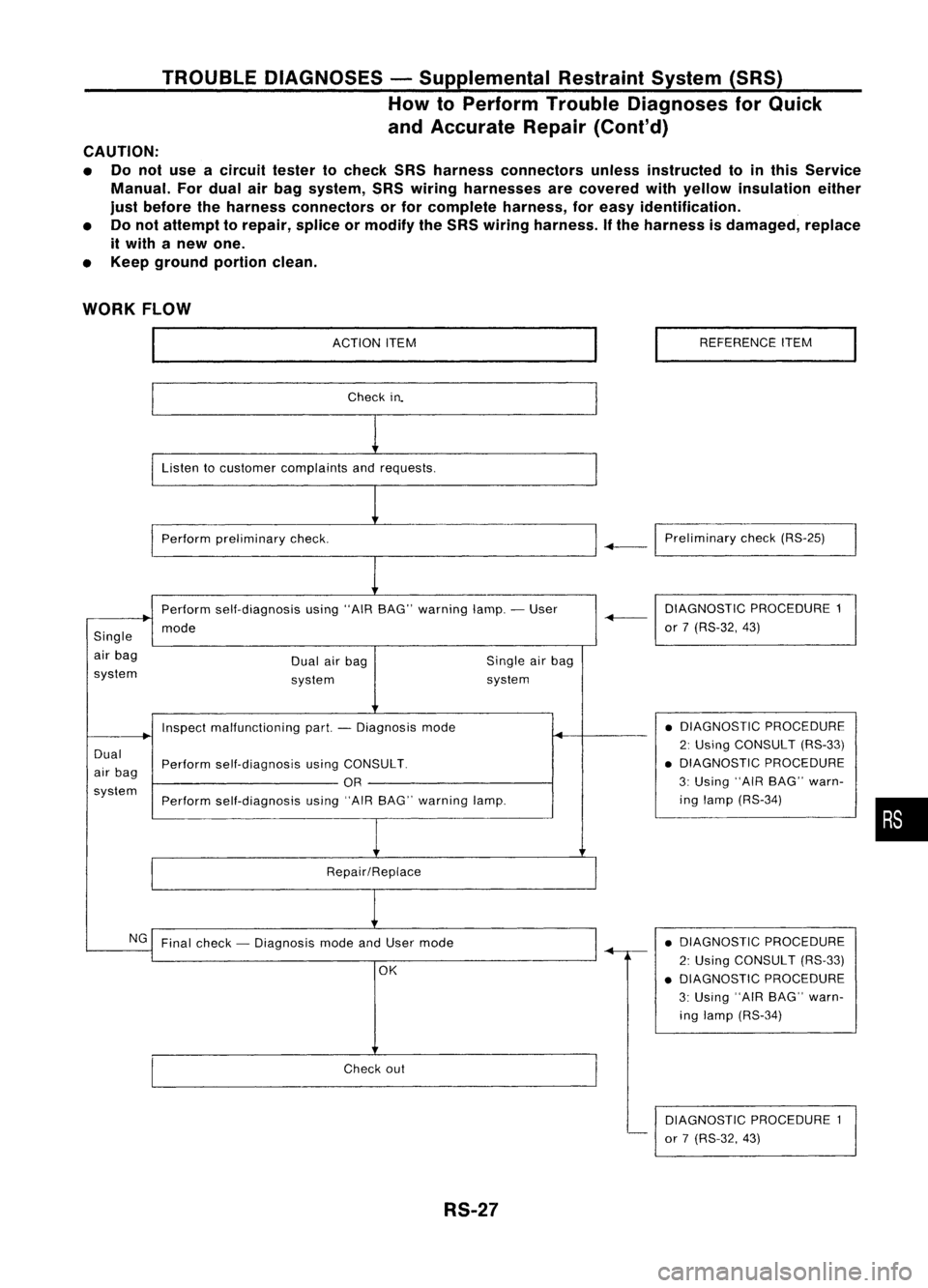
TROUBLEDIAGNOSES -Supplemental RestraintSystem(SRS)
How toPerform TroubleDiagnoses forQuick
and Accurate Repair(Cont'd)
CAUTION:
• Donot use acircuit testertocheck SRSharness connectors unlessinstructed tointhis Service
Manual. Fordual airbag system, SRSwiring harnesses arecovered withyellow insulation either
just before theharness connectors orfor complete harness,foreasy identification.
• Donot attempt torepair, spliceormodify theSRS wiring harness. Ifthe harness isdamaged, replace
it with anew one.
• Keep ground portionclean.
WORK FLOW
ACTIONITEM
Check in.
Listen tocustomer complaints andrequests.
Perform preliminary check. REFERENCE
ITEM
-+-1
Preliminary check(RS-25)
Perform self-diagnosis using"AIRBAG" warning lamp.-User
mode
Single
air bag
system Dual
airbag
system Single
airbag
system DIAGNOSTIC
PROCEDURE1
-+-
or7(RS-32, 43)
Dual
air bag
system Inspect
malfunctioning part.-Diagnosis mode
Perform self-diagnosis usingCONSULT.
OR
Perform self-diagnosis using"AIRBAG" warning lamp.
Repair/Replace •
DIAGNOSTIC PROCEDURE
2: Using CONSULT (RS-33)
• DIAGNOSTIC PROCEDURE
3: Using "AIRBAG" warn-
ing lamp (RS-34)
•
NG Final check -Diagnosis modeandUser mode
OK
Check out
RS-27 •
DIAGNOSTIC PROCEDURE
2: Using CONSULT (RS-33)
• DIAGNOSTIC PROCEDURE
3: Using "AIRBAG" warn-
ing lamp (RS-34)
DIAGNOSTIC PROCEDURE1
or 7(RS-32, 43)
Page 1649 of 1701
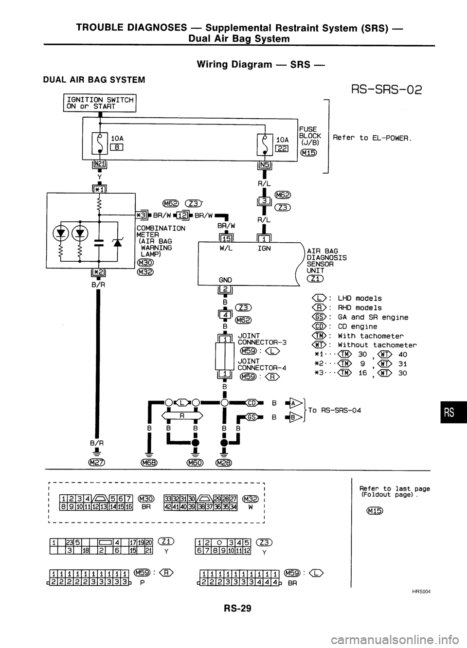
TROUBLEDIAGNOSES -Supplemental RestraintSystem(SRS)-
Dual AirBag System
Wiring Diagram -SRS -
DUAL AIRBAG SYSTEM
RS-SRS-02
IGNITION SWITCH
ON orSTART
::} ToAS-SAS-D.
•
Refer
toEL-POWER.
@:
GAand SRengine
@:
CDengine
@:
Withtachometer
@:
Without tachometer
~f1 ...
@
30
@
40
,
*2
@
9
@
31
*3
@
16
'@
30
,
AIR
BAG
DIAGNOSIS
SENSOR
UNIT
ill)
FUSE
BLOCK
(JIB)
(M15)
10A
1221
IGN
GNO
~ B
~(ll)
C:J~
B
rn~
I
~g~~~CTOR-3
~:
JOINT
CONNECTOR-4
~~:
I
,..O~O-O-ID-
I
<:
R
:>
I~
B B B BB
1
L..t t.J
~ (M60)~
~
(ll)"
*~
BRIW ~ BRIW-.
COMBINATION BRIW
METER ~
(AIR BAG 111511
WARNING WIL
LAMP)
(M30)
~
10A
W
BIR
.....
~
11*.21
BIR
~----------------------------------~
Refertolast page
(Foldout page).
L ~
em
y
(IT)
y
~(M59):
~P
ITIII:illJIIIII
~:
~ BR
HRS004
RS-29
Page 1650 of 1701
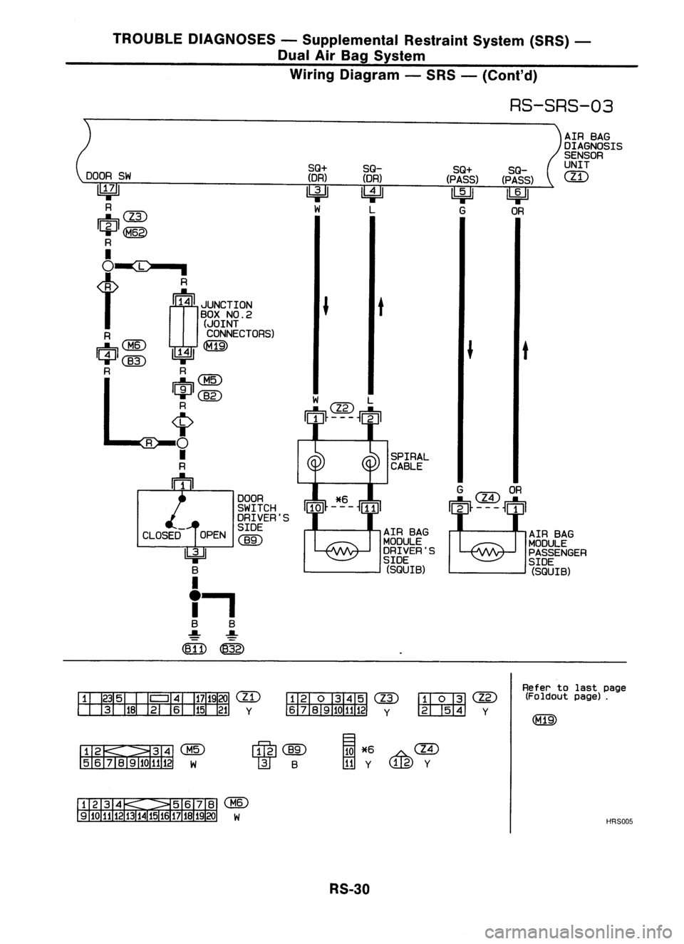
TROUBLEDIAGNOSES -Supplemental RestraintSystem(SRS)-
Dual AirBag System
Wiring Diagram -SRS -
{Co nt'd)
RS-SRS-03
AIRBAG
DIAGNOSIS
SENSOR
UNIT
em
AIR BAG
MODULE
PASSENGER
SIDE (SQUIB)
t
SQ-
(PASS)
~
OR
SQ+
(PASS)
~
G
SPIRAL
CABLE
AIR BAG
MODULE
DRIVER'S
SIDE (SQUIB)
t
SQ-
(DR)
~
L
SQ+
(DR)
l!:jJJ
W
DOOR
SWITCH
DRIVER'S
SIDE
@)
OPEN
"=iJ
B
I
f.
B B
~ ~
(B11)
@
DOOR
SW
~
R
~@
ICiJI~
R
I
BOXNO.2
(..JOINT
R CONNECTORS)
I~I ~~: ; ~
R R
I"'m:\
~~
I~IC@
R
<;>
R
0
•
R
m
em
y
@
~cm
y ~ y
Refer
tolast page
(Foldout page).
~~@
5 6lil~1112 W
rfrnl(]ID
l]f
B
~
*6
A,.@
t!!Iy ~y
@
W
HRS005
RS-30