1995 NISSAN ALMERA N15 light
[x] Cancel search: lightPage 1136 of 1701
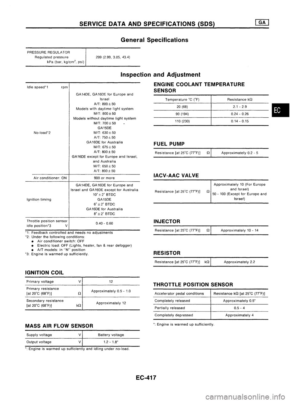
SERVICEDATAANDSPECIFICATIONS (SOS)
General Specifications
PRESSURE REGULATOR
Regulated pressure
kPa (bar, kg/cm
2,
psi) 299
(2.99, 3.05,43.4)
Idle speed'1
rpm
Inspection
andAdjustment
ENGINE COOLANT TEMPERATURE
SENSOR
Temperature
'c
('F) Resistancekn
20 (68) 2.1
-2.9
•
90
(194) 0.24-0.26
110 (230) 0.14-0.15
No-load'2
Air conditioner: ONGA
14DE, GA16DE forEurope and
Israel
AIT: 800:1:50
Models withdaytime lightsystem
MIT: 800:1:50
Models withoutdaytime lightsystem
M/T: 700:1:50
GA15DE
M/T: 630:1: 50
A/T: 750:1: 50
GA 16DE forAustralia
M/T: 675:1: 50
A/T: 800:1:50
GA16DE exceptforEurope andIsrael,
and Australia
M/T: 650:1:50
A/T: 800:1: 50
900 ormore
FUEL
PUMP
Resistance [at25'C (77'F)] n
IACV-AAC VALVE
Approximately
0.2-5
Ignition timing GA
14DE, GA16DE forEurope and
Israel andGA16DE except forAustralia
10':1:2' BTDC
GA15DE
6':1:2' BTDC
GA16DE forAustralia
8':1:2' BTDC Resistance
[at25'C (77'F)) Approximately
10(For Europe
n andIsrael)
50 -100 (Except forEurope and
Israel)
0.40. 0.60
Throttle
position sensor
idle position'3 V
'1: Feedback controlled andneeds noadjustments
'2: Under thefollowing conditions:
• Air conditioner switch:OFF
• Electric load:OFF(Lights, heater,fan
&
rear defogger)
• A/T models: in"N" position
'3: Engine iswarmed upSUfficiently.
IGNITION COIL INJECTOR
Resistance [at25'C (77'F)) n
RESISTOR
Resistance [at25'C (77'F)] kn Approximately
10.14
Approximately 2.2
THROTTLE POSITIONSENSOR
Primary
voltage
Primary resistance
[at 20'C (68'F)]
Secondary resistance
[at 20'C (68'F)]
V
n
kn
12
Approximately 0.5-1.0
Approximately 12 Accelerator
pedalconditions
Completely released
Partially released
Completely depressed Resistance
kn[at25'C (77'F))
Approximately 0.5'
0.5 -4
Approximately 4
MASS AIRFLOW SENSOR
':
Engine iswarmed upsufficiently.
Supply voltage
Output voltage
V
V
Battery
voltage
1.2 -1.8'
': Engine iswarmed upSUfficiently andidling under no-load.
EC-417
Page 1137 of 1701
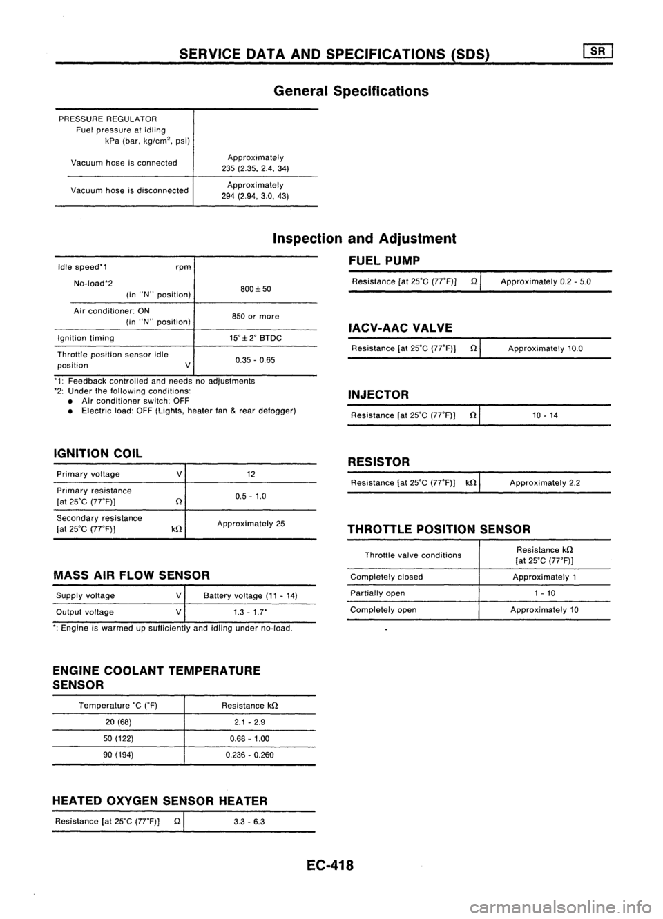
SERVICEDATAANDSPECIFICATIONS (SOS)
General Specifications
PRESSURE REGULATOR
Fuel pressure atidling
kPa (bar, kg/cm
2,
psi)
Vacuum hoseisconnected
Vacuum hoseisdisconnected Approximately
235 (2.35. 2.4.34)
Approxi mately
294 (2.94, 3.0,43)
Idle speed'1
No-load'2 rpm
(in "N" position) 800:1:50
Inspection
andAdjustment
FUEL PUMP
Resistance [at25'C (77'F)] n
Approximately 0.2-5.0
Air conditioner: ON
(in "N" position)
Ignition timing
Throttle position sensoridle
position V850
ormore
IACV-AACVALVE
15':1:2' BTDC
Resistance[at25'C (77'F)] n
0.35 -0.65 Approximately
10.0
'1: Feedback controlled andneeds noadjustments
'2: Under thefollowing conditions:
• Air conditioner switch:OFF
• Electric load:OFF(Lights, heaterfan
&
rear defogger)
IGNITION COIL INJECTOR
Resistance [at25'C (77'F)) n'
1_0_-_1_4 _
RESISTOR
Primary voltage
Primary resistance
[at 25'C (77'F))
V
12
0.5 -1.0 Resistance
[at25'C (77'F)) kn ApproXimately 2.2
Secondary resistance
[at 25'C (77'F))
kn
Approximately
25
THROTTLEPOSITIONSENSOR
MASS AIRFLOW SENSOR
Supply voltage
Output voltage
V
V
Battery
voltage (11-14)
1.3 -1.7'
Throttle
valveconditions
Completely closed
Partially open
Completely open Resistance
kn
[at 25'C (77'F)]
Approximately 1
1 - 10
Approximately 10
': Engine iswarmed upsufficiently andidling under no-load.
ENGINE COOLANT TEMPERATURE
SENSOR
Temperature
'c
('F)
20 (68)
50 (122)
90 (194) Resistance
kn
2.1-2.9
0.68 -1.00
0.236 -0.260
HEATED OXYGEN SENSOR HEATER
Resistance [at25'C (77'F)] n
I
3.3-6.3
EC-418
Page 1225 of 1701
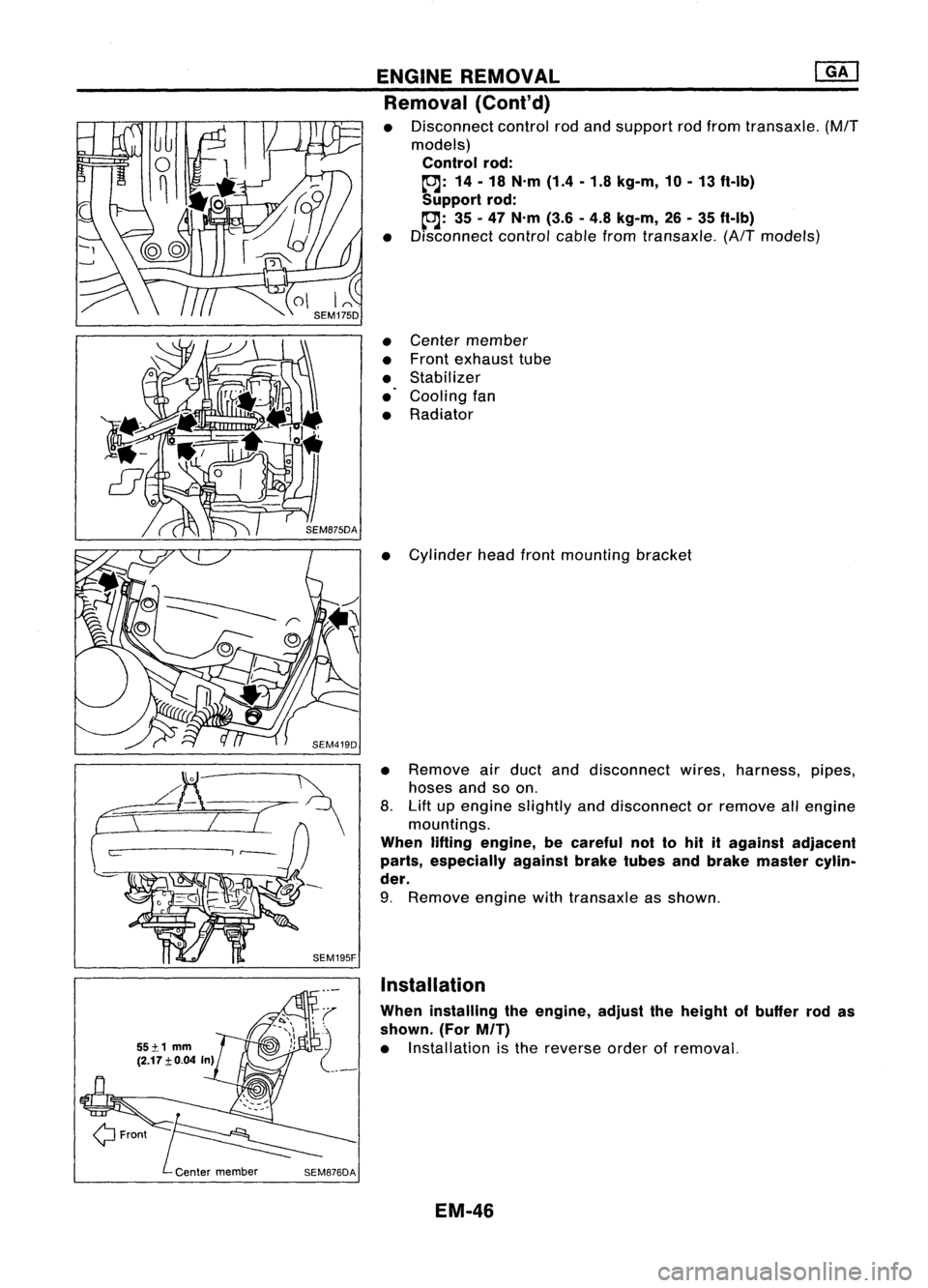
ENGINEREMOVAL
mJ
Removal (Cont'd)
• Disconnect controlrodand support rodfrom transaxle.
(M/T
models)
Control rod:
to:J:
14-18 N.m (1.4-1.8 kg-m, 10-13 ft-Ib)
Support rod:
to:J:
35-47 N.m (3.6-4.8 kg-m, 26-35 ft-Ib)
• Disconnect controlcablefromtransaxle.
(A/Tmodels)
• Center member
• Front exhaust tube
• Stabilizer
• Cooling fan
• Radiator
• Cylinder headfrontmounting bracket
• Remove airduct anddisconnect wires,harness, pipes,
hoses andsoon.
8. Lift upengine slightly anddisconnect orremove allengine
mountings.
When liftingengine, becareful nottohit itagainst adjacent
parts, especially againstbraketubesandbrake master cylin-
der.
9. Remove enginewithtransaxle asshown.
Installation
When installing theengine, adjusttheheight ofbuffer rodas
shown. (ForM/T)
• Installation isthe reverse orderofremoval.
EM-46
Page 1274 of 1701
![NISSAN ALMERA N15 1995 Service Manual CYLINDERHEAD
ill]
Assembly (Cont'd)
10. Install valvecomponent parts.
• Install valves withlarger diameter headonthe intake side.
•
Wide pitch
Narrow pitch
Paint mark
Cylinder headside
S NISSAN ALMERA N15 1995 Service Manual CYLINDERHEAD
ill]
Assembly (Cont'd)
10. Install valvecomponent parts.
• Install valves withlarger diameter headonthe intake side.
•
Wide pitch
Narrow pitch
Paint mark
Cylinder headside
S](/manual-img/5/57349/w960_57349-1273.png)
CYLINDERHEAD
ill]
Assembly (Cont'd)
10. Install valvecomponent parts.
• Install valves withlarger diameter headonthe intake side.
•
Wide pitch
Narrow pitch
Paint mark
Cylinder headside
SEM085D•
Always usenew valve oilseal.
Refer toOIL SEAL REPLACEMENT.
• Before installing valveoilseal, install valvespring seat.
.' Install valvespring (uneven pitchtype) withitsnarrow
pitched sidetoward cylinder headside(paint mark).
• After installing valvecomponent parts,tapvalve stemtip
with plastic hammer toassure aproper fit.
11. Check hydraulic lashadjusters.
a. Push rocker armathydraulic lashadjuster location, andsee
if rocker armmoves. Ifitmoves atleast 1mm (0.04 in),it
indicates thatthere isair inthe high pressure chamber.
Noise willbeemitted fromhydraulic lashadjuster ifengine
is started without bleeding air.
b. Remove hydraulic lashadjuster anddipinacontainer filled
with engine oil.While pushing plungerasshown infigure,
lightly pushcheck ballusing athin rod. Airiscompletely
bled when plunger nolonger moves.
Air cannot bebled from thistype oflash adjuster byrunning the
engine.
SEM093D
• rEngine oil
- - , t-=1=i
Proper
rod
SEM772C
Rocker arm9UVide
Rock~rarm
Shim
Hydraulic
I
.,h
.dj"'"
i\\ j
12.
Install rocker arms,shims, rockerarmguides andhydrau-
lic lash adjusters.
CAUTION: Install allparts intheir original positions.
SEM202D EM-95
Page 1275 of 1701
/1!!i1*Shim
~ Rocker armguide
Ij9 ~~
Valve collet
~ I:::
Valvespring
l!I
retainer
I!1!i! ~
'Valve spring
~ ~~ ~Valve springseat
j
Valveoilseal ~
Valve
SEM364DCYLINDER
HEAD ~
Assembly (Cont'd)
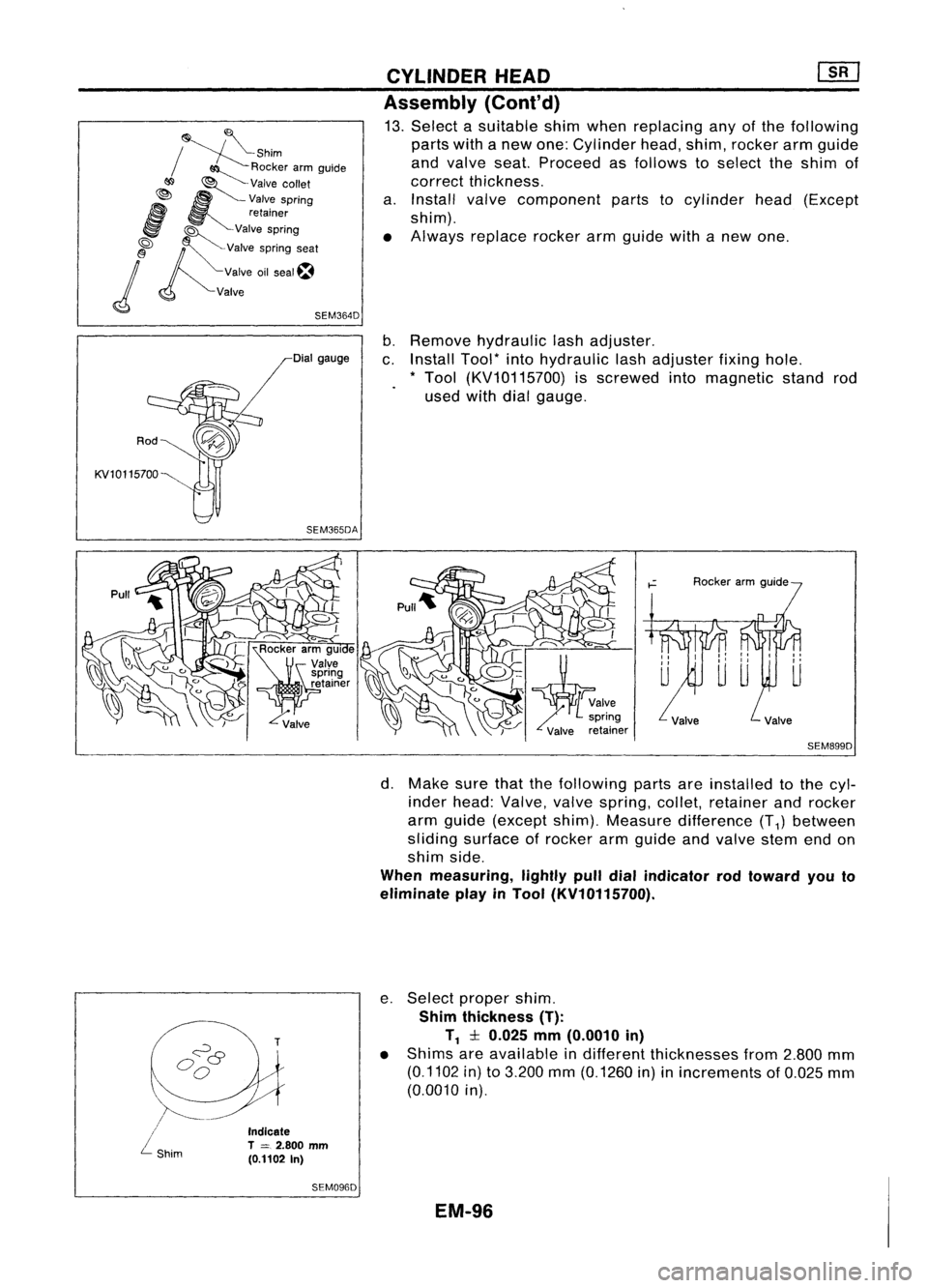
13. Select asuitable shimwhen replacing anyofthe following
parts withanew one: Cylinder head,shim, rocker armguide
and valve seat.Proceed asfollows toselect theshim of
correct thickness.
a. Install valvecomponent partstocylinder head(Except
shim).
• Always replace rockerarmguide withanew one.
Rod
KV10115700 Dial
gauge
SEM365DA
b.
Remove hydraulic lashadjuster.
c. Install Tool*intohydraulic lashadjuster fixinghole.
* Tool (KV10115700) isscrewed intomagnetic standrod
used withdialgauge.
SEM899D
\.
/~-
/
L
shim
Indicate
T
=
2.800 mm
(0.1102 In)
SEM096D
d.
Make surethatthefollowing partsareinstalled tothe cyl-
inder head: Valve, valvespring, collet,retainer androcker
arm guide (except shim).Measure difference (T
1)
between
sliding surface ofrocker armgUide andvalve stemendon
shim side.
When measuring, lightlypulldialindicator rodtoward youto
eliminate playinTool (KV10115700).
e. Select proper shim.
Shim thickness (T):
T
1
:l:0.025 mm(0.0010 in)
• Shims areavailable indifferent thicknesses from2.800 mm
(0.1102 in)to3.200 mm(0.1260 in)inincrements of0.025 mm
(0.0010 in).
EM-96
Page 1365 of 1701
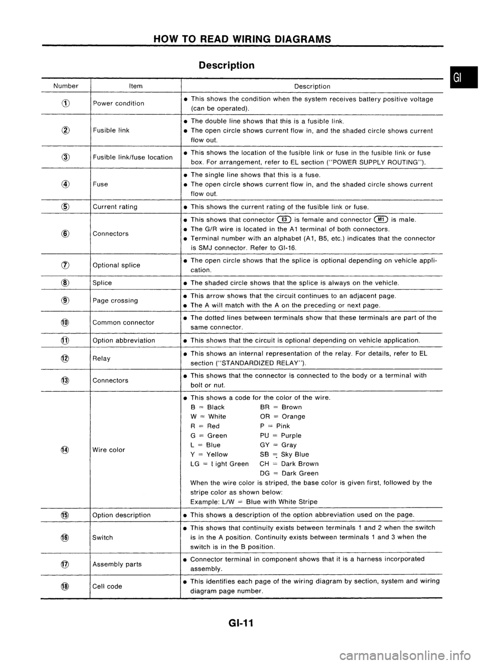
HOWTOREAD WIRING DIAGRAMS
Description
Number Item Description
CD
Power
condition •
This shows thecondition whenthesystem receives batterypositive voltage
(can beoperated) .
• The double lineshows thatthisisafusible link.
@
Fusiblelink
•The open circle shows current flowin,and theshaded circleshows current
flow out.
link/fuse location •
This shows thelocation ofthe fusible linkorfuse inthe fusible linkorfuse
box. Forarrangement, refertoEL section ("POWER SUPPLYROUTING") .
• The single lineshows thatthisisafuse.
@
Fuse
•The open circle shows current flowin,and theshaded circleshows current
flow out.
CID
Current
rating
•This shows thecurrent ratingofthe fusible linkorfuse .
• This shows thatconnector
@)
isfemale andconnector
@
ismale .
@
Connectors •
The G/R wire islocated inthe A1 terminal ofboth connectors.
• Terminal numberwithanalphabet (A1, B5, etc.) indicates thattheconnector
is SMJ connector. RefertoGI-16 .
rJ)
Optionalsplice •
The open circle shows thatthesplice isoptional depending onvehicle appli-
cation.
@
Splice •The shaded circleshows thatthesplice isalways onthe vehicle.
@
Page
crossing •
This arrow shows thatthecircuit continues toan adjacent page.
• The Awill match withtheAon the preceding ornext page .
@)
Commonconnector •
The dotted linesbetween terminals showthatthese terminals arepart ofthe
same connector.
@
Option
abbreviation •This shows thatthecircuit isoptional depending onvehicle application.
@
Relay •
This shows aninternal representation ofthe relay. Fordetails, refertoEL
section ("STANDARDIZED RELAY").
@
Connectors •
This shows thattheconnector isconnected tothe body oraterminal with
bolt ornut.
• This shows acode forthe color ofthe wire.
B
=
Black BR
=
Brown
W
=
White OR
=
Orange
R
=
Red P
=
Pink
G
=
Green PU
=
Purple
@
Wire
color L
=
Blue GY
=
Gray
Y
=
Yellow SB
=:
Sky Blue
LG
=
Light Green CH
=
Dark Brown
DG
=
Dark Green
When thewire color isstriped, thebase color isgiven first,followed bythe
stripe colorasshown below:
Example: LlW
=
Blue withWhite Stripe
@
Optiondescription •
This shows adescription ofthe option abbreviation usedonthe page.
• This shows thatcontinuity existsbetween terminals 1and 2when theswitch
@)
Switch is
inthe Aposition. Continuity existsbetween terminals 1and 3when the
switch isinthe Bposition .
@
Assembly
parts •
Connector terminalincomponent showsthatitis aharness incorporated
assembly .
@
Cell
code •
This identifies eachpage ofthe wiring diagram bysection, systemandwiring
diagram pagenumber.
GI-11
•
Page 1371 of 1701
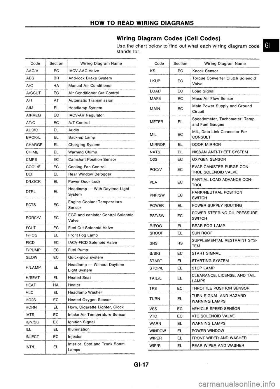
HOWTOREAD WIRING DIAGRAMS
Wiring Diagram Codes(CellCodes)
Use thechart below to'find outwhat each wiring diagram code•
stands for,
Code Section WiringDiagram Name
AACIV ECIACV-AAC
Valve
ABS BR
Anti-lock BrakeSystem
A/C HAManualAirConditioner
A/CCUT ECAir
Conditioner CutControl
A/T ATAutomatic Transmission
AIM ELHeadlamp System
AIRREG ECIACV-Air Regulator
AT/C ECA/TControl
AUDIO ELAudio
BACK/L ELBack-up Lamp
CHARGE ELCharging System
CHIME ELWarning Chime
CMPS EC
Camshaft PositionSensor
COOllF ECCooling
FanControl
DEF ELRearWindow Defogger
D/LOCK ELPowerDoorLock
DTRL ELHeadlamp
-With Daytime Light
System
ECTS ECEngine
Coolant Temperature
Sensor
EGR andcanister ControlSolenoid
EGRCIV EC
Valve
FCUT ECFuel
CutSolenoid Valve
F/FOG ELFront
FogLamp
FICO ECIACV-FICD
SolenoidValve
F/PUMP ECFuel
Pump
GLOW ECQuick-glow
system
H/LAMP ELHeadlamp
-Without Daytime
Light System
H/SEAT ELHeated
Seat
HEAT HA
Heater
HLC ELHeadlamp
Washer
H02S ECHeated
Oxygen Sensor
HORN ELHorn,
Cigarette Lighter,Clock
IATS ECIntake
AirTemperature Sensor
IGN/SG ECIgnition
Signal
ILL ELIllumination
INJECT ECInjector
INT/L ELInterior,
SpotandTrunk Room
Lamps Code
Section WiringDiagram Name
KS ECKnock
Sensor
LKUP ECTorque
Converter ClutchSolenoid
Valve
LOAD ECLoadSignal
MAFS ECMass
AirFlow Sensor
MAIN ECMain
Power Supply andGround
Circuit
METER ELSpeedometer,
Tachometer,Temp.
and Fuel Gauges
MIL ECMIL,
Data LinkConnector For
CONSULT
MIRROR ELDOOR
MIRROR
NATS ELNISSAN
ANTI-THEFT SYSTEM
02S ECOXYGEN
SENSOR
EC EVAP
CANISTER PURGECON-
PGCIV TROLSOLENOID VALVE
PLA ECPARTIAL
LOADADVANCE CON-
TROL
EC PARK/NEUTRAL
POSITION
PNP/SW SWITCH
POWER ELPOWER
SUPPLY ROUTING
POWER STEERING OILPRESSURE
PST/SW EC
SWITCH
R/FOG ELREAR
FOGLAMP
SROOF ELSUN
ROOF
SUPPLEMENTAL RESTRAINTSYS-
SRS RS
TEM
S/SIG ECST
ART SIGNAL
START ELSTARTING
SYSTEM
STOP/L ELSTOP
LAMP
TAllIL ELCLEARANCE,
LICENSE,ANDTAIL
LAMPS
TPS ECTHROTTLE
POSITIONSENSOR
TURN SIGNAL ANDHAZARD
TURN EL
WARNING LAMPS
VSS ECVEHICLE
SPEEDSENSOR
VTC ECVTC
SOLENOID VALVE
WARN ELWARNING
LAMPS
WINDOW ELPOWER
WINDOW
WIPER ELFRONT
WIPERANDWASHER
WIP/R ELREAR
WIPER ANDWASHER
GI-17
Page 1373 of 1701
HOWTOPERFORM EFFICIENT DIAGNOSIS FORANELECTRICAL INCIDENT
Incident Simulation Tests
INTRODUCTION
Sometimes thesymptom isnot present whenthevehicle isbrought infor service.
If
possible, re-create
the conditions presentatthe time ofthe incident. Doingsomay help avoid aNo Trouble FoundDiag-
nosis. Thefollowing sectionillustrates waystosimulate theconditionslenvironment underwhich the
owner experiences anelectrical incident.
The section isbroken intothesixfollowing topics:
• Vehicle vibration
• Heat sensitive
• Freezing
• Water intrusion
• Electrical load
• Cold orhot start up
Get athorough description ofthe incident fromthecustomer. Itis important forsimulating thecondi-
tions ofthe problem.
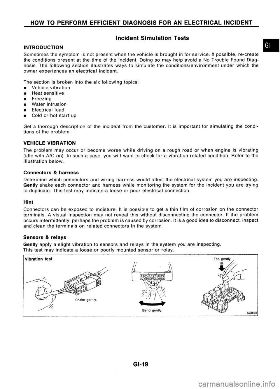
VEHICLE VIBRATION
The problem mayoccur orbecome worsewhiledriving onarough roadorwhen engine isvibrating
(idle with
AIC
on). Insuch acase, youwillwant tocheck foravibration relatedcondition. Refertothe
illustration below.
Connectors
&
harness
Determine whichconnectors andwiring harness wouldaffecttheelectrical systemyouareinspecting.
Gently
shakeeachconnector andharness whilemonitoring thesystem forthe incident youaretrying
to duplicate. Thistestmay indicate aloose orpoor electrical connection.
Hint
Connectors canbeexposed tomoisture. Itis possible toget athin film ofcorrosion onthe connector
terminals. Avisual inspection maynotreveal thiswithout disconnecting theconnector. Ifthe problem
occurs intermittently, perhapstheproblem iscaused bycorrosion. Itis agood ideatodisconnect, inspect
and clean theterminals onrelated connectors inthe system.
Sensors
&
relays
Gently
applyaslight vibration tosensors andrelays inthe system youareinspecting.
This testmay indicate aloose orpoorly mounted sensororrelay.
•
Vibration test
Bendgently.
GI-19
Tap
gently.
8GI839