1995 NISSAN ALMERA N15 light
[x] Cancel search: lightPage 1448 of 1701
TROUBLEDIAGNOSES
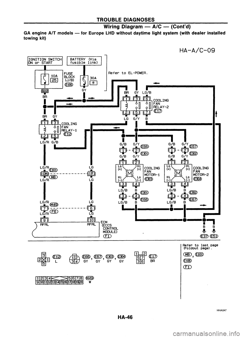
Wiring Diagram -
A/C -
(Cont'd)
GA engine AfTmodels -for Europe LHDwithout daytime lightsystem (withdealer installed
towing kit)
HA-A/C-09
BATTERY (Via
fusible link)
t
COOLING
FAN
MOTOR-2
~
•
I
GIS
G/Y
ID
$-$@g)
GIS
G/Y
mrn
La Hi
1+) 1+)
-
COOLING
FAN
MOTOR-1
Hi La~ HiLa
H H~ HH
IkjJJ ~ ~~
LG/S S
@D
LG/SS~
IrjJ~ -
$
66
IrjJ~-
i$/
6
LG/S S
@
LG/SS
ID
I-I
&-_I!__~.,
S S
~ ~
~~
SR
GYLG/S
~ ~RELAY-2
~~~rn> LG
G/Y
S
I '
-
.
i
I
T-
GIS G/Y@
IciJ~ -
t~J1@D
GIS G/Y
mm
La Hi
1+) (+)
Refer
toEL-POWER.
I
ECM
(ECCS
CONTROL
MODULE)
em
FUSE
BLOCK 30A
(JIB)
r-e-t
(El06) ~
IQ;OI
GY
BR _
1_
f-p:=_e:::::-
BR GY
1:Jt1 :lJIICOOLING
n
FAN
U
RELAY-1
IbjJJ
ILi=U
LG/R G/B
I
LG/R~ LG
~\EJQ!I ~
~M8----------~
Li~
I
LG/R~ LG
Iqp~-~~---------~qpl
LG/R
CEID
LG
m
ffiJl
2
RFRL RFRL
¥
@
2 1L
5
rffi\
@ID,
@?),
(f303), ~
t:]JY
GYGYGY GY
"2
57
@
36 SR
Refer
tolast page
(Foldout page).
CHID,
(El06)
em
@
W
HHA047
HA-46
Page 1491 of 1701
PRE-DELIVERYINSPECTIONITEMS
Shown belowarePre-delivery InspectionItemsrequired forthe new vehicle. Itis recommended that
necessary itemsotherthanthose listedherebeadded, payingdueregard tothe conditions ineach
country.
Perform applicable itemsoneach model. Consult textofthis section forspecifications .
UNDER HOOD-engine off
o
Radiator coolantlevelandcoolant hosecon-
nections forleaks
o
Battery fluidlevel, specific gravityandcondi-
tions ofbattery terminals
o
Drive beltstension
D
Fuel filter forwater ordusts, andfuel lines
and connections forleaks
[] Engine oillevel andoilleaks
D
Clutch andbrake reservoir fluidlevel and
fluid lines forleaks
o
Windshield andrear window washerand
headlamp cleanerreservoir fluidlevel
D
Power steering reservoir fluidlevel andhose
connections forleaks
ON INSIDE ANDOUTSIDE
D
Remove frontspring/strut spacer(Ifapplica-
ble)
D
Operation ofall instruments, gauges,lights
and accessories
o
Operation ofhorn(s), wiperandwasher
[] Steering lockforoperation
[] Check airconditioner forgas leaks
o
Front andrear seats, andseat belts foroper-
ation
n
All moldings, trimsandfittings forfitand
alignment
[J
Allwindows foroperation andalignment
n
Hood, trunklid,door panels forfitand align-
ment
[1
Latches, keysandlocks foroperation
rl
Weatherstrips foradhesion andfit
[l
Headlamp aiming
I~ Tighten wheelnuts(Inc. inner nutsifapplica-
ble)
IJ Tire pressure (Inc.spare tire)
Il
Check frontwheels fortoe-in
IJ Install clock/voltmeter/room lampfuse(If
applicable)
~ Install deodorizing filtertoair purifier (If
applicable)
~ Remove wiperbladeprotectors (Ifapplicable)
UNDER
BODY
o
Manual transmission/transaxle, transferand
differential gearoillevel
D
Brake andfuel lines andoil/fluid reservoirs
for leaks
D
Tighten boltsandnuts ofsteering linkageand
gear box,suspension, propellershaftsand
drive shafts
~ Tighten rearbody boltsandnuts (Models with
wooden bedonly)
ROAD TEST
D
Clutch operation
D
Parking brakeoperation
[J
Service brakeoperation
D
Automatic transmission/transaxle shifttiming
and kickdown
[] Steering controlandreturnability
o
Engine performance
D
Squeaks andrattles
ENGINE OPERATING ANDHOT
D
Adjust idlemixture andspeed (andignition
timing*1)
n
Automatic transmission/transaxle fluidlevel
~ Engine idlingandstop knob operation (Diesel
only)
FINAL INSPECTION
n
Install necessary parts(outside mirror,wheel
covers, seatbelts, mat,carpet ormud flaps)
[1
Inspect forinterior andexterior metaland
paint damage
[] Check forspare tire,jack, tools (wheel
chock), andliterature
n
Wash, cleaninterior andexterior
"1: Not required onmodels withadirect ignition system
~ :Not appiicable tothis model.
•
MA-5
Page 1492 of 1701
GENERALMAINTENANCE
General maintenance includesthoseitemswhich should bechecked duringthenormal day-to-day
operation ofthe vehicle. Theyareessential ifthe vehicle isto continue operating properly.Theowners
can perform thechecks andinspections themselves orthey canhave theirNISSAN dealersdothem.
Item
OUTSIDE THEVEHICLE
The maintenance itemslistedhereshould beperformed fromtimetotime, unless oth-
erwise specified.
Tires
Check thepressure withagauge periodically whenataservice station, including
the spare, andadjust tothe specified pressureifnecessary. Checkcarefully fordamage,
cuts orexcessive wear.
Windshield wiperblades
Checkforcracks orwear ifthey donot wipe properly.
Doors andengine hood
Check thatalldoors, theengine hood,thetrunk lidand back
door operate properly. Alsoensure thatalllatches locksecurely. Lubricate hinges,
latches, rollersandlinks ifnecessary. Makesurethatthesecondary latchkeeps thehood
from opening whentheprimary latchisreleased.
When driving inareas usingroadsaltorother corrosive materials, checkforlubrication
frequently.
Tire rotation
Tiresshould berotated every
10,000
km
(6,000
miles).
INSIDE THEVEHICLE
The maintenance itemslistedhereshould bechecked onaregular basis,suchaswhen
performing periodicmaintenance, cleaningthevehicle, etc.
Lights
Makesurethattheheadlights, stoplights, taillights, turnsignal lights,andother
lights arealloperating properlyandinstalled securely. Alsocheck headlight aim.
Warning lightsandbuzzers/chimes
Makesurethatallwarning lightsandbuzzers/chimes
are operating properly.
Steering wheel
Check forchange inthe steering conditions, suchasexcessive freeplay,
hard steering orstrange noises.
Free play: Lessthan35mm (1.38 in)
Seat belts
Check thatallparts ofthe seat beltsystem (e.g.buckles, anchors, adjusters
and retractors) operateproperly andsmoothly, andareinstalled securely. Checkthebelt
webbing forcuts, fraying, wearordamage.
UNDER THEHOOD ANDVEHICLE
The maintenance itemslisted hereshould bechecked periodically e.g.each timeyou
check theengine oilorrefuel.
Windshield washerfluid
Check thatthere isadequate fluidinthe tank.
Engine coolant level
Check thecoolant levelwhen theengine iscold.
Engine oillevel
Check thelevel afterparking thevehicle onalevel spotandturning off
the engine.
Brake andclutch fluidlevels
Makesurethatthebrake andclutch fluidlevels arebetween
the "MAX" and"MIN" linesonthe reservoir.
Battery
Checkthefluid level ineach cell.Itshould bebetween the"MAX" and"MIN"
lines.
MA-6
Reference
pages
MA-51
MA-50
MA-19,38
MA-24, 33,41
MA-45,47
Page 1511 of 1701
ENGINEMAINTENANCE ~
Changing OilFilter (Cont'd)
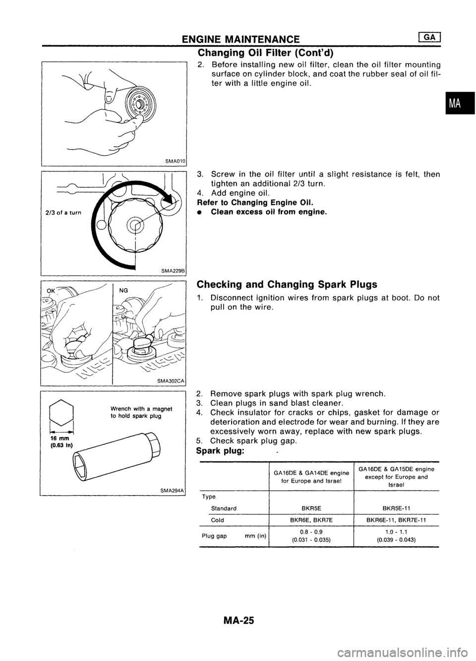
2. Before installing newoilfilter, clean theoilfilter mounting
surface oncylinder block,andcoat therubber sealofoil fil-
ter with alittle engine oil.
SMA010
•
2/3 ofaturn
g 16
mm
(0.63 In) SMA302CA
Wrench withamagnet
to hold spark plug
SMA294A
3.
Screw inthe oilfilter untilaslight resistance isfelt, then
tighten anadditional 2/3turn.
4. Add engine oil.
Refer toChanging EngineOil.
• Clean excess oilfrom engine.
Checking andChanging SparkPlugs
1. Disconnect ignitionwiresfromspark plugsatboot. Donot
pull onthe wire.
2. Remove sparkplugswithspark plugwrench.
3. Clean plugsinsand blastcleaner.
4. Check insulator forcracks orchips, gasket fordamage or
deterioration andelectrode forwear andburning. Ifthey are
excessively wornaway, replace withnewspark plugs.
5. Check sparkpluggap.
Spark plug:
GA16DE&GA14DE engine GA16DE
&GA15DE engine
for Europe andIsrael except
forEurope and
Israel
Type Standard BKR5E
BKR5E-11
Cold BKR6E,BKR7E BKR6E-11,
BKR7E-11
Plug gap mm(in) 0.8
-0.9 1.0-1.1
(0.031 -0.035) (0.039-0.043)
MA-25
Page 1520 of 1701
![NISSAN ALMERA N15 1995 Service Manual ENGINEMAINTENANCE [}[]
Changing EngineOil(Cont'd)
4. Check oillevel.
5. Start engine andcheck areaaround drainplugandoilfilter
for oilleakage.
6. Run engine forafew minutes, thenturnitoff. After NISSAN ALMERA N15 1995 Service Manual ENGINEMAINTENANCE [}[]
Changing EngineOil(Cont'd)
4. Check oillevel.
5. Start engine andcheck areaaround drainplugandoilfilter
for oilleakage.
6. Run engine forafew minutes, thenturnitoff. After](/manual-img/5/57349/w960_57349-1519.png)
ENGINEMAINTENANCE [}[]
Changing EngineOil(Cont'd)
4. Check oillevel.
5. Start engine andcheck areaaround drainplugandoilfilter
for oilleakage.
6. Run engine forafew minutes, thenturnitoff. After several
minutes, checkoillevel.
Refill oil10this
"H" level.
Do not overfill.
SMA390C
Changing OilFilter
1. Remove oilfilter withTool.
WARNING:
Be careful nottoburn yourself, asthe engine andtheengine
oil are hot.
2. Clean oilfilter mounting surfaceoncylinder block.Coat
rubber sealofnew oilfilter withengine oil.
2/3
ofaturn
-------
OK SMA010
3.Screw inthe oilfilter untilaslight resistance isfelt, then
tighten anadditional 2/3turn.
4. Add engine oil.
Refer toChanging EngineOil.
• Clean excess oilfrom engine.
Changing SparkPlugs(Platinum-tipped type)
1. Disconnect ignitionwiresfromspark plugsatboot. Donot
pull onthe wire.
MA-34
Page 1529 of 1701
![NISSAN ALMERA N15 1995 Service Manual
2/3
ofaturn
ENGINE
MAINTENANCE @Q]
Changing EngineOilFilter (Cont'd)
3. Screw oilfilter onuntil aslight resistance isfelt, then tighten
an additional 2/3turn.
4. Warm upengine andcheck oillevel NISSAN ALMERA N15 1995 Service Manual
2/3
ofaturn
ENGINE
MAINTENANCE @Q]
Changing EngineOilFilter (Cont'd)
3. Screw oilfilter onuntil aslight resistance isfelt, then tighten
an additional 2/3turn.
4. Warm upengine andcheck oillevel](/manual-img/5/57349/w960_57349-1528.png)
2/3
ofaturn
ENGINE
MAINTENANCE @Q]
Changing EngineOilFilter (Cont'd)
3. Screw oilfilter onuntil aslight resistance isfelt, then tighten
an additional 2/3turn.
4. Warm upengine andcheck oillevel.
5. Adjust oillevel ifnecessary. •
Refer toStep 4in "Changing EngineOil",MA-42.
i
• Clean excess oilfrom engine.
SMA229B Checking InjectionNozzle
1. Remove injection deliverytubesandfuel spill tube.
2. Remove nozzlewithasuitable tool[span 27mm (1.06 in)].
WARNING:
When usingnozzle tester,becareful nottoallow diesel fuel
sprayed fromnozzle tocome intocontact withyour hand or
body, andmake surethatyour eyes areproperly protected.
3. Clean andcheck nozzles.
4. Install nozzle toinjection nozzletesterandbleed airfrom
flare nut.
5. Check initialinjection pressure bypumping testerhandle
one time persecond.
EF791A
6.Install injector topressure tester.
7. Check initialinjection pressure bypumping testerhandle
slowly (onetime persecond).
Injection pressure:
12,749 kPa(127.5 bar,130kg/cm
2,
1,849psi)
• Always checkinitialinjection pressure beforeinstalling new
nozzle.
Good
\
I
,
,
I
Wrong SEF672A
8.Check fuelspray pattern bypumping testerhandle quickly
(4 or 6times persecond).
9. Ifinitial injection pressure orinjection nozzleisnot normal,
adjust orclean injection nozzleorreplace it.
Refer toEC section forinjection pressure adjustment.
10. Install allinjection nozzlesandsecurely connectfuelspill
tube anddelivery tubes.
11. Bleed airfrom fuelsystem andcheck forfuel leakage with
engine running.
EF794A
MA.43
Page 1530 of 1701
ENGINEMAINTENANCE
Checking InjectionNozzle(Cont'd)
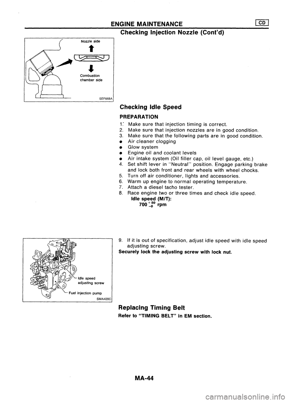
Nozzle side
Combustion
chamber side
SEF668A Checking IdleSpeed
PREPARATION
1: Make surethatinjection timingiscorrect.
2. Make surethatinjection nozzlesareingood condition.
3. Make surethatthefollowing partsareingood condition.
• Air cleaner clogging
• Glow system
• Engine oiland coolant levels
• Air intake system (Oilfiller cap,oillevel gauge, etc.)
4. Set shift lever in"Neutral" position.Engageparkingbrake
and lock both front andrear wheels withwheel chocks.
5. Turn offair conditioner, lightsandaccessories.
6. Warm upengine tonormal operating temperature.
7. Attach adiesel tachotester.
8. Race engine twoorthree times andcheck idlespeed.
Idle speed (M/T):
700~go rprn
9.
If
itis out ofspecification, adjustidlespeed withidlespeed
adjusting screw.
Securely locktheadjusting screwwithlock nut.
Idle speed
adjusting screw
Fuel injection pump
SMA420C
Replacing TimingBelt
Refer to"TIMING BELT"inEM section.
MA-44
Page 1549 of 1701
REMOVALANDINSTALLATION
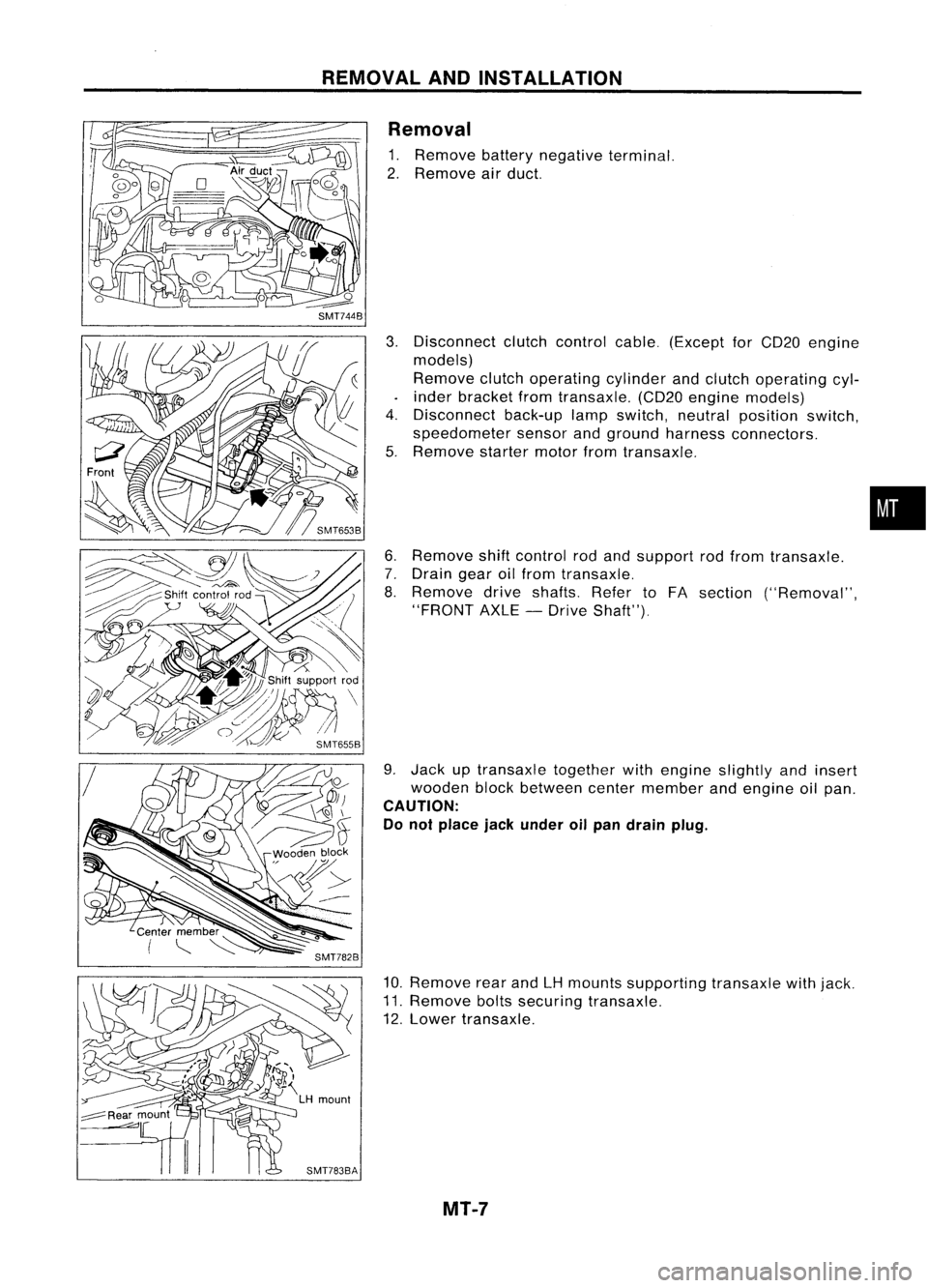
Removal
1. Remove batterynegative terminal.
2. Remove airduct.
3. Disconnect clutchcontrol cable.(Except forCD20 engine
models)
Remove clutchoperating cylinderandclutch operating cyl-
inder bracket fromtransaxle. (CD20engine models)
4. Disconnect back-uplampswitch, neutralposition switch,
speedometer sensorandground harness connectors.
5. Remove startermotorfromtransaxle.
6. Remove shiftcontrol rodand support rodfrom transaxle.
7. Drain gearoilfrom transaxle.
8. Remove driveshafts. RefertoFA section ("Removal",
"FRONT AXLE-Drive Shaft").
9. Jack uptransaxle togetherwithengine slightly andinsert
wooden blockbetween centermember andengine oilpan.
CAUTION:
Do not place jackunder oilpan drain plug.
10. Remove rearandLHmounts supporting transaxlewithjack.
11. Remove boltssecuring transaxle.
12. Lower transaxle.
MT-7
•