Page 1555 of 1701
DISASSEMBLV
I
RSSF30A
&
RSSF31 A
I
5th shift -
fork
Suitable
tool
SMT571
SMT082A SMT577
SMT579
1.
Remove transmission casewhile slightly tiltingitto prevent
5th shift forkfrom interfering withcase.
2. Draw outreverse idlerspacer andfork shaft, thenremove
5th and 3rd
&
4th shift forks.
• Becareful nottolose shifter cap.
3. Remove controlbracket with1st
&
2nd shift fork.
• Becareful nottolose shifter cap.
4. Remove gearcomponents fromclutch housing.
- RS5F30A-
a. Remove threescrews anddetach bearing retainer.
• One ofthese threescrews istorx type andshould be
removed withasuitable tool,asshown.
b. Remove inputshafttogether withmainshaft bytapping
lightly.
• Always withdraw mainshaft straightout.Failure todo so
can damage resinoilchannel onclutch housing side.
• Do not draw outreverse idlershaft fromclutch housing
because thesefittings willbeloose.
• When removing inputshaft, becareful nottoscratch oilseal
lip with shaft spline.
MT-13
•
Page 1556 of 1701
DISASSEMBLY
I
RS5F30A
&
RS5F31 A
I
SMT580
SMT720
c.
Remove reverseidlergear andfinal drive assembly.
- RS5F31A-
a. Remove mainshaft andfinal drive assembly.
• Always withdraw mainshaft straightout.Failure todo so
can damage resinoilchannel onclutch housing side.
SMT721
SMT646A
Soft hammer
SMT722
b.
Remove bearingretainer securing bolts.
c. Remove inputshaft together withbearing retainer and
reverse idlergear bytapping lightly.
• Do not draw outreverse idlershaft fromclutch housing
because thesefittings willbeloose.
• Becareful nottoscratch oilseal lipwith shaft spline when
removing inputshaft.
MT-14
Page 1571 of 1701

~casecover"U--0-ring
~spacer
Mainshaft rearbearing ~ Mainshaft
outer race ~
0
bearing
- \ adjusting
shim
I ~--
SMT613AA
SMT599 ADJUSTMENT
I
RS5F30A
&
RS5F31A
I
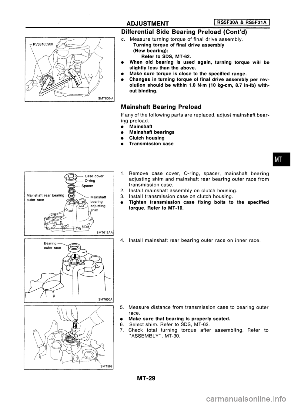
Differential SideBearing Preload(Cont'd)
c. Measure turningtorqueoffinal drive assembly.
Turning torqueoffinal drive assembly
(New bearing):
Refer toSOS, MT-62.
• When oldbearing isused again, turning torquewillbe
slightly lessthan theabove.
• Make suretorque isclose tothe specified range.
• Changes inturning torqueoffinal drive assembly perrev-
olution shouldbewithin 1.0N'm (10kg-em, 8.7in-Ib) with-
out binding.
Mainshaft BearingPreload
If any ofthe following partsarereplaced, adjustmainshaft bear-
il}g preload.
• Mainshaft
• Mainshaft bearings
• Clutch housing
• Transmission case
1. Remove casecover, O-ring, spacer, mainshaft bearing
adjusting shimandmainshaft rearbearing outerracefrom
transmission case.
2. Install mainshaft assemblyonclutch housing.
3. Install transmission caseonclutch housing.
• Tighten transmission casefixing boltstothe specified
torque. RefertoMT-10.
4. Install mainshaft rearbearing outerraceoninner race.
5. Measure distancefromtransmission casetobearing outer
race.
• Make surethatbearing isproperly seated.
6. Select shim.RefertoSDS, MT-62.
7. Check totalturning torqueafterassembling. Referto
"ASSEMBLY", MT-30.
MT-29
•
Page 1574 of 1701
ASSEMBLYI
RSSF30A
&
RSSF31 A
I
SMT720
c.
Install mainshaft assembly.
• Take carenottodamage oilchannel wheninserting main-
shaft intoclutch housing.
9. Apply grease toshifter caps,theninstall itto control
bracket. Installcontrol bracket with1st
&
2nd shift fork.
10. Install 3rd
&
4th and 5thshift forks.
11. Insert forkshaft.
• Apply multi-purpose greasetosupport springbefore install-
ing.
12. Install reverse idlerspacer.
13. Apply recommended sealanttomating surface ofclutch
housing.
14. Install transmission caseonclutch housing.
15. Measure totalturning torque.
Total (Final drive+Mainshaft) turningtorque(New
bearing): Refer toSOS, MT-62.
• When oldbearing isused again, turning torquewillbe
slightly lessthan theabove.
• Make suretorque isclose tothe specified range.
MT-32
Page 1578 of 1701
SMT6648DISASSEMBL
Y
1. Remove casecover.
I
RS5F32A
I
SMT6668
2.
Remove mainshaft bearingsnapring.
3. Remove transmission casewhile slightly tilting
it
to prevent
5th shift forkfrom interfering withcase.
5th shift
fork SMT6678
4.
Draw outreverse idlerspacer andfork shaft.
5. Remove 5thand 3rd
&
4th shift forks.
• Becareful nottolose shifter cap.
MT-36
Page 1597 of 1701
ADJUSTMENT
I
RS5F32A
I
Differential SideBearing Preload(Cont'd)
c. Measure turningtorqueoffinal drive assembly.
Turning torqueoffinal drive assembly
(New bearing):
2.9 -6.9 N'm (30-70 kg-em, 26-61 in-Ib)
• When oldbearing isused again, turning torquewillbe
slightly lessthan theabove.
• Make suretorque isclose tothe specified range.
• Changes inturning torqueoffinal drive assembly perrev-
olution shouldbewithin 1.0N'm (10kg-em, 8.7in-Ib) with-
out binding.
MT-55
•
Page 1639 of 1701

SUPPLEMENTALRESTRAINTSYSTEM(SRS)
Disposal ofAir Bag Module andSeat Belt
Pre-tensioner
• Before disposing ofair bag module andseat beltpre-tensioner, orvehicles equipped withsuch
systems, deploythesystems. Ifsuch systems havealready beendeployed duetoan accident, dis-
pose ofas indicated in"DISPOSING OFAIR BAG MODULE ANDSEAT BELTPRE-TENSIONER" (RS-
24).
• When deploying theairbag module, alwaysusetheSpecial Service Tool;Deployment tool
KV99106400.
• When deploying theairbag module andseat beltpre-tensioner, standatleast 5m (16 ft)away from
the deployment component.
• Due toheat, leave airbag module unattended formore than30minutes afterdeployment. Alsoleave
seat beltpre-tensioner unattendedformore than10minutes afterdeployment.
• Besure towear gloves whenhandling adeployed airbag module andseat beltpre-tensioner.
• Never applywater toadeployed airbag module.
• Wash yourhands cleanafterfinishing- work.
• Donot dispose ofthe airbag module andseat beltpre-tensioner un-deployed.
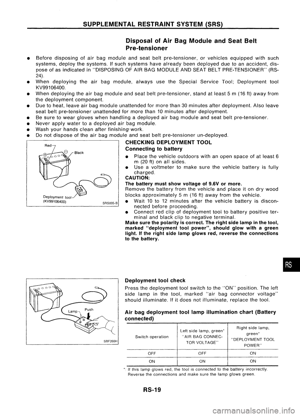
CHECKING DEPLOYMENT TOOL
Connecting tobattery
• Place thevehicle outdoors withanopen space ofat least 6
m (20
ft)
on allsides.
• Use avoltmeter tomake surethevehicle batteryisfully
charged.
CAUTION:
The battery mustshow voltage of9.6V ormore.
Remove thebattery fromthevehicle andplace iton dry wood
Deployment
tool blocksapproximately 5m (16 ft)away fromthevehicle.
(KV99106400j SRS005-B•
Wait 10to12 minutes afterthevehicle batteryisdiscon-
nected beforeproceeding.
• Connect redclip ofdeployment tooltobattery positive ter-
minal andblack cliptonegative terminal.
Make surethepolarity iscorrect. Theright sidelamp inthe tool,
marked "deployment toolpower", shouldglowwithagreen
light. Ifthe right sidelamp glows red,reverse theconnections
to the battery.
•
SBF266H Deployment
toolcheck
Press thedeployment toolswitch tothe "ON" position. Theleft
side lamp inthe tool, marked "airbagconnector voltage"
should illuminate.
If
it
does notilluminate, replacethetool.
Air bag deployment toollamp illumination chart(Battery
connected)
Leftside lamp, green' RighI
sidelamp,
Switch operation "AIR
BAGCONNEC- green'
"DEPLOYMENT TOOL
TOR VOLTAGE"
POWER"
OFF OFF ON
ON ON
ON
,. Ifthis lamp glows red,the1001 isconnecled tothe battery incorrectly.
Reverse theconnections andmake surethelamp glows green.
RS-19
Page 1673 of 1701

SST491B
SST090B ON-VEHICLE
SERVICE
Bleeding Hydraulic System
1. Raise frontendofvehicle untilwheels areclear ofthe
ground.
2. Add fluid intooiltank tospecified level.Thenquickly turn
steering wheelfullytoright andleftand lightly touchsteer-
ing stoppers.
Repeat steering wheeloperation untilfluid level nolonger
decreases.
3. Start engine.
Repeat step2.above.
• Incomplete airbleeding willcause thefollowing tooccur.
When thishappens, bleedairagain.
a. Air bubbles inreservoir tank
b. Clicking noiseinoil pump
c. Excessive buzzinginoil pump
Fluid noise mayoccur inthe valve oroil pump. Thisiscommon
when thevehicle isstationary orwhile turning thesteering
wheel slowly. Thisdoes notaffect theperformance ordurabil-
ity ofthe system.
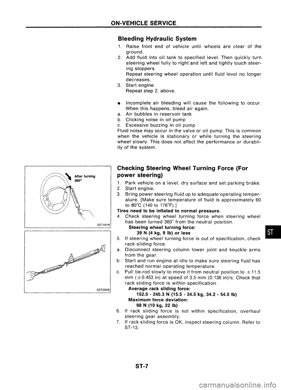
Checking SteeringWheelTurning Force(For
power steering)
1. Park vehicle onalevel, drysurface andsetparking brake.
2. Start engine.
3. Bring power steering fluiduptoadequate operating temper-
ature. [Make suretemperature offluid isapproximately 60
to 80°C (140to176°F).]
Tires needtobe inflated tonormal pressure.
4. Check steering wheelturning forcewhen steering wheel
has been turned 360°from theneutral position.
Steering wheelturning force: •
39 N(4 kg, 9Ib) orless
5.
If
steering wheelturning forceisout ofspecification, check
rack sliding force.
a. Disconnect steeringcolumnlowerjointandknuckle arms
from thegear.
b. Start andrunengine atidle tomake suresteering fluidhas
reached normaloperating temperature.
c. Pull tie-rod slowlytomove itfrom neutral position to
::l::
11.5
mm
(::l::
0.453 in)atspeed of3.5 mm (0.138 in)/s.Check that
rack sliding forceiswithin specification.
Average racksliding force:
152.0 -240.3 N(15.5 -24.5 kg,34.2 -54.0 Ib)
Maximum forcedeviation:
98 N(10 kg, 22Ib)
6.
If
rack sliding forceisnot within specification, overhaul
steering gearassembly.
7. Ifrack sliding forceisOK, inspect steering column.Referto
ST-13.
ST-7