Page 1380 of 1701
HOWTOPERFORM EFFICIENT DIAGNOSIS FORANELECTRICAL INCIDENT
Circuit Inspection (Cont'd)
VOLTAGE DROPTESTS
Voltage droptests areoften usedtofind components orcircuits whichhaveexcessive resistance. A
voltage dropinacircuit iscaused byaresistance
whenthecircuit isin operation.
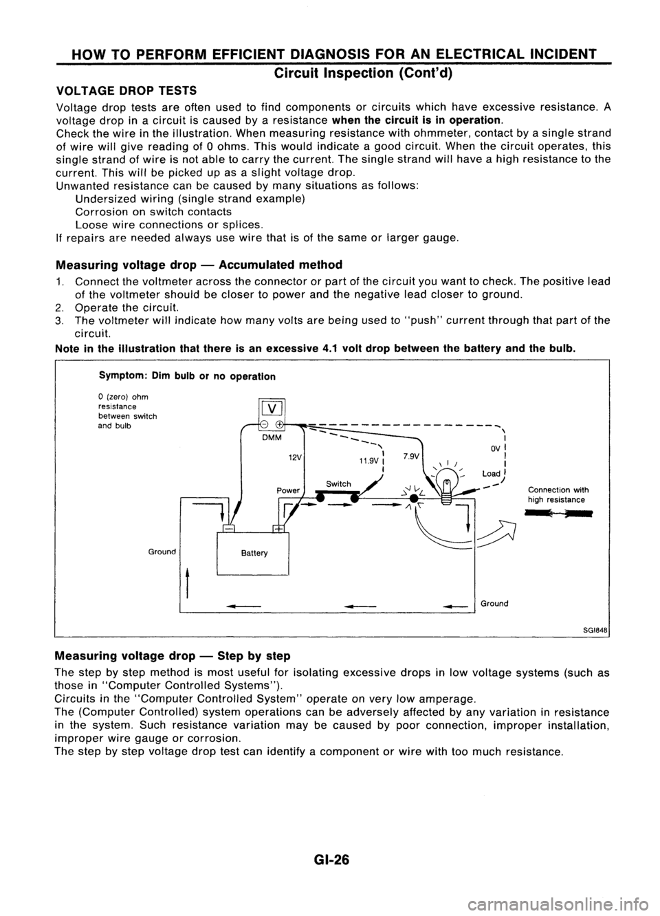
Check thewire inthe illustration. Whenmeasuring resistancewithohmmeter, contactbyasingle strand
of wire willgive reading of0ohms. Thiswould indicate agood circuit. Whenthecircuit operates, this
single strand ofwire isnot able tocarry thecurrent. Thesingle strand willhave ahigh resistance tothe
current. Thiswillbepicked upasaslight voltage drop.
Unwanted resistance canbecaused bymany situations asfollows:
Undersized wiring(single strandexample)
Corrosion onswitch contacts
Loose wireconnections orsplices.
If
repairs areneeded alwaysusewire thatisof the same orlarger gauge.
Measuring voltagedrop-Accumulated method
1. Connect thevoltmeter acrosstheconnector orpart ofthe circuit youwant tocheck. Thepositive lead
of the voltmeter shouldbecloser topower andthenegative leadcloser toground.
2. Operate thecircuit.
3. The voltmeter willindicate howmany voltsarebeing usedto"push" current through thatpart ofthe
circuit.
Note inthe illustration thatthere isan excessive 4.1volt drop between thebattery andthebulb.
Symptom: Dimbulb orno operation
Switch Connectionwith
high resistance
l ;
--
------------------~
--
\
~~~~ I
-, OVI
11.9V:
'I
I
Load)
--
12V
DMM
Battery
Ground
o
(zero) ohm
resistance
between switch
and bulb
t
•
__
Ground
SGI848
Measuring voltagedrop-Step bystep
The step bystep method ismost useful forisolating excessive dropsinlow voltage systems (suchas
those in"Computer ControlledSystems").
Circuits inthe "Computer ControlledSystem"operateonvery lowamperage.
The (Computer Controlled) systemoperations canbeadversely affectedbyany variation inresistance
in the system. Suchresistance variationmaybecaused bypoor connection, improperinstallation,
improper wiregauge orcorrosion.
The step bystep voltage droptestcan identify acomponent orwire withtoomuch resistance.
GI-26
Page 1382 of 1701
HOWTOPERFORM EFFICIENT DIAGNOSIS FORANELECTRICAL INCIDENT
Circuit Inspection (Cont'd)
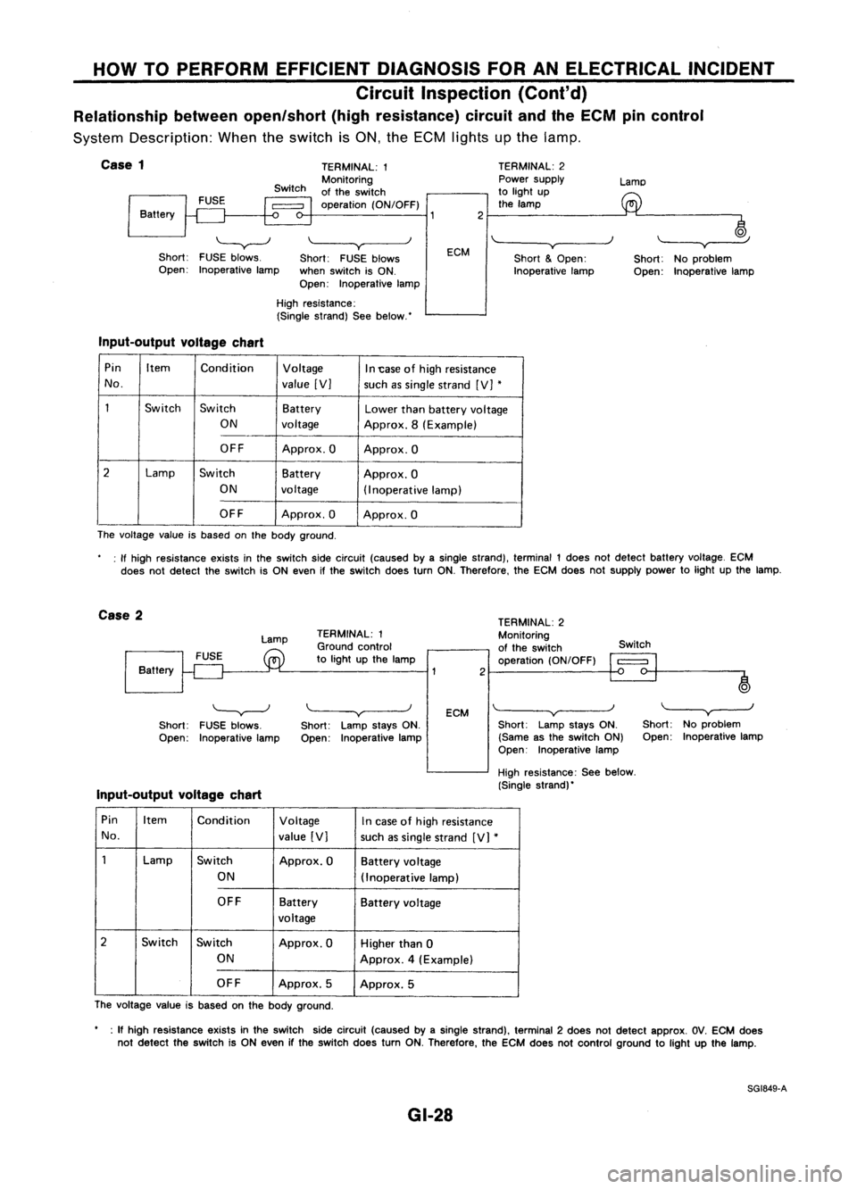
Relationship betweenopen/short (highresistance) circuitandtheECM pincontrol
System Description: Whentheswitch isON, theECM lights upthe lamp.
j
Case
1
Battery
'-----v--J
Short: FUSEblows.
Open: Inoperative lamp TERMINAL:
1
Monitoring
of the switch
operation (ON/OFF)
\~--~y
Short: FUSEblows
when switch isON.
Open: Inoperative lampECM
2
TERMINAL:
2
Power supply
to light up
the lamp
'"-----v~----)
Short
&
Open:
Inoperative lampLamo
~
Short: Noproblem
Open: Inoperative lamp
High resistance:
(Single strand) Seebelow.'
Input-output voltagechart
Pin Item
Condition Voltage
In1:ase ofhigh resistance
No. value[V]
suchassingle strand [V]
*
1
Switch
Switch Battery
Lowerthanbattery voltage
ON voltage Approx.8(Example)
OFF Approx.O Approx.O
2
Lamp
Switch Battery
Approx.O
ON voltage
(Inoperativelamp)
OFF Approx.O Approx.O
The voltage valueisbased onthe body ground.
: If high resistance existsinthe switch sidecircuit (caused byasingle strand), terminal 1does notdetect battery voltage. ECM
does notdetect theswitch isON even ifthe switch doesturnON.Therefore. theECM does notsupply powertolight upthe lamp.
Case 2
Lamp
Battery TERMINAL:
1
Ground control
to light upthe lamp
2TERMINAL:
2
Monitoring
of the switch
operation (ON/OFF) Switch
o
)
'---v---J
Short: FUSEblows.
Open: Inoperative lamp
Input-output voltagechart
\.----v
Short: LampstaysON.
Open: Inoperative lamp
ECM
\~--~v~--_.J
Short: LampstaysON.
(Same asthe switch ON)
Open: Inoperative lamp
High resistance: Seebelow.
(Single strand)'
"---y-----.J
Short: Noproblem
Open: Inoperative lamp
Pin Item Condition Voltage
Incase ofhigh resistance
No. value[V]
suchassingle strand [V]
*
1
Lamp
Switch
Approx.OBatteryvoltage
ON (Inoperat ivelamp)
OFF Battery
Batteryvoltage
voltage
2
Switch Switch Approx.OHigherthan0
ON Approx.4(Example)
OFF Approx.5
Approx.5
The voltage valueisbased onthe body ground.
• :If high resis1ance existsinthe switch sidecircuit (caused byasingle strand), terminal 2does notdetect approx. OV.ECM does
not detect theswitch isON even ifthe switch doesturnON.Therefore, theECM does notcontrol ground tolight upthe lamp.
SG1849-A
GI-28
Page 1400 of 1701
SAEJ1930 TERMINOLOGY LIST
SAE J1930 Terminology List(Cont'd)
***:
Not applicable
NEW TERM NEW
ACRONYM /
OLDTERM
ABBREVIATION
Evaporative emissioncanisterpurgecontrol EVAPcanister purgecon-
Canister purgecutvalve
valve trol
valve
Evaporative emissioncanisterventcontrol EVAPcanister ventcontrol
***
valve valve
Evaporative emissioncanisterpurgevolume EVAPcanister purgevol-
Canister purgecontrol valve
control valve ume
control valve
Evaporative emissioncontrolsystem pressure EVAP
control system pres-
***
sensor suresensor
Evaporative emissionshutvalve EVAP
shutvalve Shutoffvalve
Evaporative emissionsystem EVAPsystem Evaporative
emissioncontrolsystem
Exhaust gasrecirculation valve EGR
valve EGRvalve
Exhaust gasrecirculation control-BPTvalveEGRC-BPT valve BPT
valve
Exhaust gasrecirculation control-solenoid
EGRC-solenoidvalveEGR
control solenoid valve
valve
Exhaust gasrecirculation temperaturesensorEGRtemperature sensorExhaustgastemperature sensor
Flash electrically erasableprogrammable
FEEPROM
***
read onlymemory
Flash erasable programmable readonly
FEPROM
**.
memory
Flexible fuelsensor FFS
***
Flexible fuelsystem
FFsystem
***
Heated Oxygen sensor H02SExhaustgassensor
Idle aircontrol system lACsystem Idlespeed control
Idle aircontrol valve-air regulator IACV-airregulator Airregulator
Idle aircontrol valve-auxiliary aircontrol
IACV-AACvalve Auxiliaryaircontrol (AAC)valve
valve
Idle aircontrol valve-FICO solenoidvalve
IACV-FICDsolenoidvalve FICOsolenoid valve
Idle aircontrol valve-idle upcontrol solenoid IACV-idleupcontrol sole-
Idleupcontrol solenoid valve
valve noidvalve
Idle speed control-FI pot ISC-FIpot FIpot
Idle speed control system ISCsystem
***
Ignition controlmodule ICM
***
Indirect fuelinjection system IFIsystem
***
Intake airtemperature sensor IATS Airtemperature sensor
Knock
***
Detonation
Knock sensor
KSDetonation
sensor
Malfunction indicatorlamp MIL
Checkengine light
Manifold absolutepressure MAP
***
Manifold absolutepressure/Barometric pres-MAP/BARO switchsolenoid
***
sure switch solenoid valve valve
Manifold absolutepressure sensor MAPS
**.
Manifold differential pressure MOP
***
Manifold differential pressuresensor MOPS
***
GI-46
Page 1408 of 1701
PRECAUTIONSANDPREPARATION
Special Service Tools(Cont'd)
CR-14 compressor
Tool number
Tool name
KV99106700
Clutch discwrench
KV991 06800
Pulley installer Description
NT351
NT352
Removing
shaftnutand clutch disc
Installing pulley
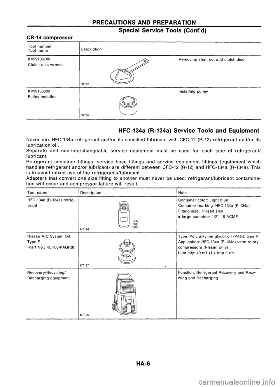
HFC-134a (R-134a)ServiceToolsandEquipment
Never mixHFC-134a refrigerant and/oritsspecified lubricantwithCFC-12 (R-12)refrigerant and/orits
lubrication oil.
Separate andnon-interchangeable serviceequipment mustbeused foreach typeofrefrigerant/
lubricant.
Refrigerant containerfittings,servicehosefittings andservice equipment fittings(equipment which
handles refrigerant and/orlubricant) aredifferent between CFC-12(R-12)andHFC-134a (R-134a).This
is to avoid mixed useofthe refrigerants/lubricant.
Adapters thatconvert onesize fitting toanother mustnever beused: refrigerant/lubricant contamina-
tion willoccur andcompressor failurewillresult.
Tool name
Description Note
HFC-134a (R-134a)refrig-
~~
Container
color:Lightblue
erant Containermarking:HFC-134a (R-134a)
Fitting size:Thread size
• large contai ner1/2"-16 ACME
NT196
Nissan A/CSystem Oil Type:Polyalkyline glycoloil(pAG), typeR
Type R
~
Application:
HFC-134a(R-134a)vanerotary
(Part No.:KLHOO-PAGRO)
compressors(Nissanonly)
Lubricity: 40me (1.4 Imp
fI
oz)
NT197
Recovery/Recycling/
~
Function:
Refrigerant RecoveryandRecy-
Recharging equipment
":'s
Q"'~
cling
andRecharging
==
•
~ t:J
~
II
NT195
HA-6
Page 1409 of 1701
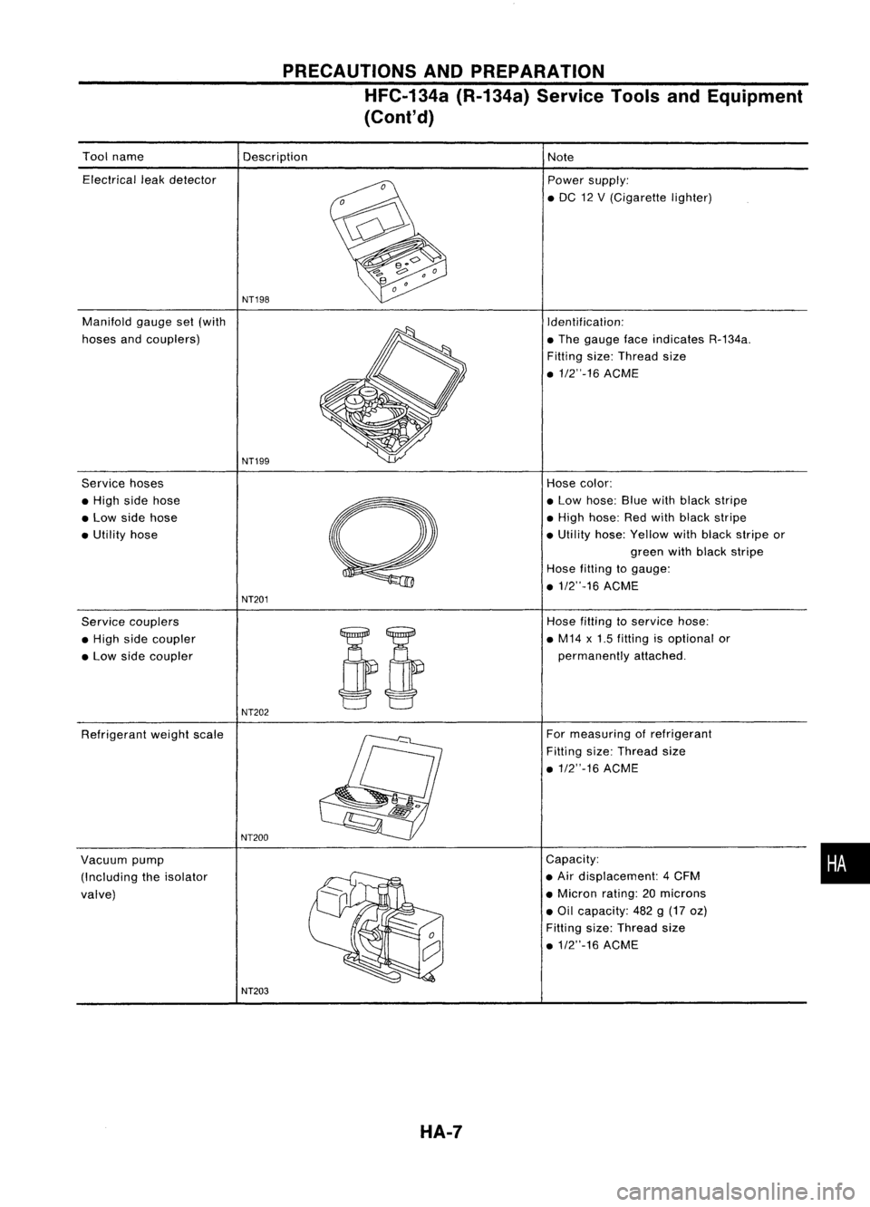
PRECAUTIONSANDPREPARATION
HFC-134a (R-134a)ServiceToolsandEquipment
(Cont'd)
Tool name
Electrical leakdetector
Manifold gaugeset(with
hoses andcouplers)
Service hoses
• High sidehose
• Low side hose
• Utility hose
Service couplers
• High sidecoupler
• Low side coupler
Refrigerant weightscale
Vacuum pump
(Including theisolator
valve) Description
NT19S
NT199
NT201
NT202
NT200
NT203 HA-7
Note
Power supply:
• DC 12V(Cigarette lighter)
Identification:
• The gauge faceindicates R-134a.
Filling size:Thread size
• 1/2"-16 ACME
Hose color:
• Low hose: Bluewithblack stripe
• High hose: Redwith black stripe
• Utility hose:Yellow withblack stripe or
green withblack stripe
Hose filting togauge:
• 1/2"-16 ACME
Hose filling to
service
hose:
• M14 x1.5 fitting isoptional or
permanently attached.
For measuring ofrefrigerant
Fitting size:Thread size
.1/2"-16 ACME
Capacity:
• Air displacement: 4CFM
• Micron rating:20microns
• Oil capacity: 482g(17 oz)
Fitting size:Thread size
.1/2"-16 ACME
•
Page 1415 of 1701
DESCRIPTION
Control Operation
LHO models RHO
models
FAN CONTROL KNOB
This knob turns thefan ONand OFF, andcontrols fanspeed.
MODE CONTROL KNOB
This knob controls theoutlet airflow.
TEMPERATURE CONTROLKNOB
This knob allows adjustment ofthe temperature ofthe outlet air.
RECIRCULATION (REC)SWITCH
OFF position:
Outside airisdrawn intothepassenger compartment.
ON position:
Interior airisrecirculated insidethevehicle.
The indicator lampwillalso light.
AIR CONDITIONER SWITCH
The airconditioner switchcontrols the
Ale
system. Whentheswitch isdepressed withthefan ON, the
compressor willturn ON.The indicator lampwillalso light.
The airconditioner coolingfunction operates onlywhen theengine isrunning.
HA-13
•
Page 1419 of 1701
RHA318F
4.Check temperature decrease
~~ ~~~nC~ef~~~~~~ur~ cont:olknobtofull cold.
air atdischarge airoutlets.
TROUBLE
DIAGNOSES
Operational Check(Cont'd)
3. Check recirculation
1) Pre~s recirculation switch.
2) ~.eclrculati~n indicatorshouldlight
Isten forIntake doorposition ch'an
blower soundchange slightly). ge(you should hear
RHA319F
5.Check temperature increase
~~ ~~rn ~efmperatu:e controlknobtofull hot
ec orhot airatdischarge airoutlets:
RHA320F
6.Check airconditioner switch
Turn fancontrol knobtothe desired 1
a~? push theairconditioner 'th (to 4-speed) position
dltlOner.
SWI
ctoturn ONtheaircon-
The indicator lightshould com .
ON. eon when airconditioner is
•
RHA321F
HA-17
Page 1436 of 1701
TROUBLEDIAGNOSES
Circuit Diagram -Air Conditioner
DUAL-PRESSURE
SWITCH
AIR
CONDITIONER
RELAY
THERMO
CONTROL
AMP.
IT
o
f-
U1
H
~
IT
W
I
f-
AIC
SWITCH
M
BLOWER
MOTOR
FAN
RESISTOR
GE
C
FAN SWITCH
OFF1234
GA
D
o
uo
HH
[LO
IZW
>w>
U..J....J
404
HUJ>
IT
o
..JI-
«u
~w
IT
I-
wo
IIT
f-(L
IT
o
U1
U1
W
IT
(L
~
o
u
RECIRCULA
nON
SWITCH
1
AIT models
MIT
models
For Europe andIsrael
Except
@
GA engine models
Except
f
or Europe, Israe 1and Austra 1ia
GA eng ine
f
or Europe, Israe1and Austra 1ia and SReng Ine
Except
@
LHD
AIT
models forEurope without daytIme lightsystem
Except
@
41.
@
44
@:
@:
@:
@:
@:
@:
@:
@:
:
@:
*1
To
illumination
system
HHA001
HA-34