1995 NISSAN ALMERA N15 light
[x] Cancel search: lightPage 793 of 1701
TROUBLEDIAGNOSES -General Description
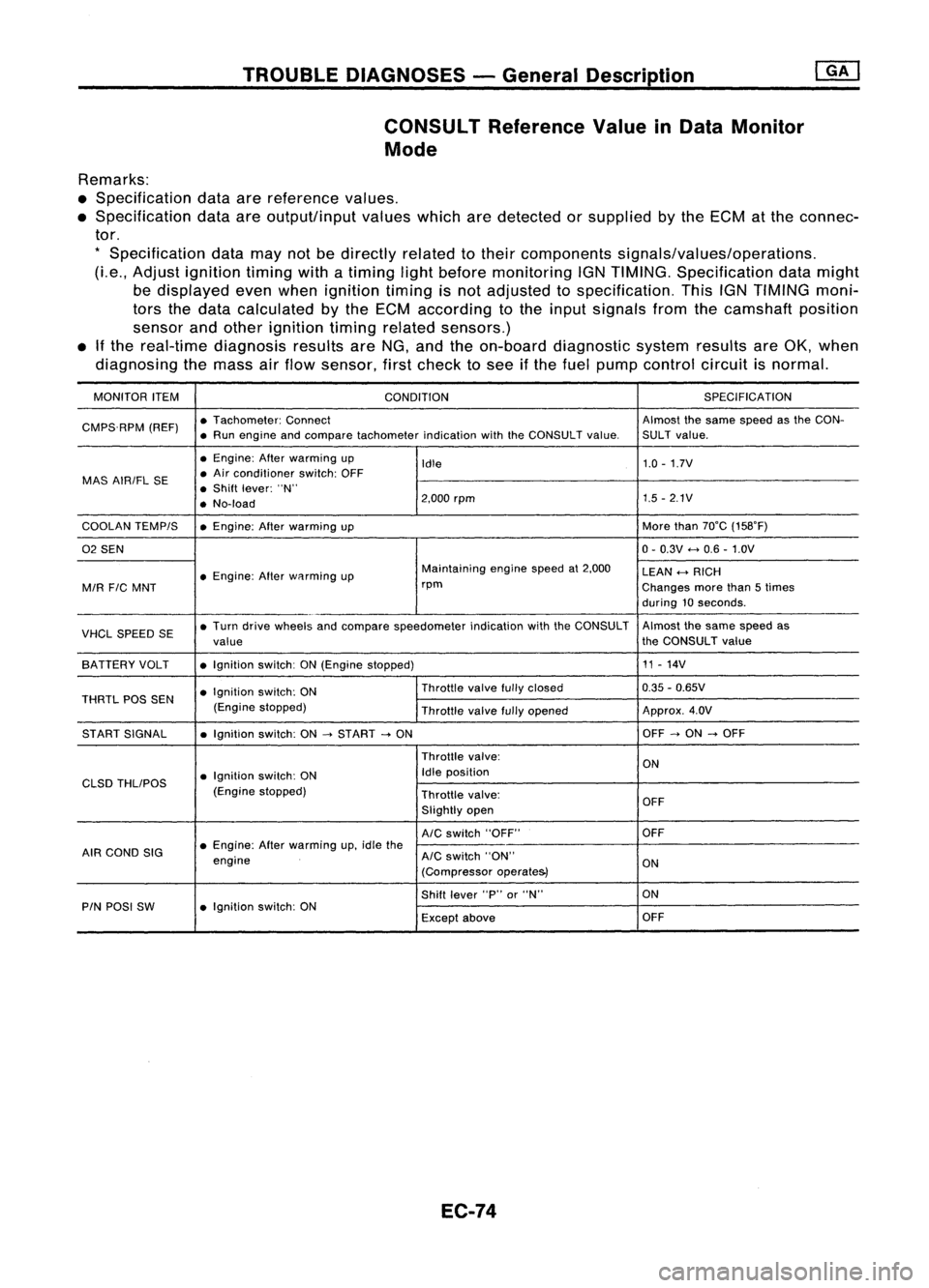
CONSULT ReferenceValueinData Monitor
Mode
Remarks:
• Specification dataarereference values.
• Specification dataareoutput/input valueswhicharedetected orsupplied bythe ECM atthe connec-
tor.
*
Specification datamaynotbedirectly relatedtotheir components signals/values/operations.
(Le., Adjust ignition timingwithatiming lightbefore monitoring IGNTIMING. Specification datamight
be displayed evenwhen ignition timingisnot adjusted tospecification. ThisIGNTIMING moni-
tors thedata calculated bythe ECM according tothe input signals fromthecamshaft position
sensor andother ignition timingrelated sensors.)
• Ifthe real-time diagnosis resultsareNG, and theon-board diagnostic systemresultsareOK, when
diagnosing themass airflow sensor, firstcheck tosee ifthe fuel pump control circuitisnormal.
MONITOR ITEM
CONDITION SPEC
IFICA TION
CMPS.RPM (REF)•
Tachometer: Connect Almostthesame speed asthe CON-
• Run engine andcompare tachometer indicationwiththeCONSULT value.SULT value.
• Engine: Afterwarming up
Idle 1.0
-1.7V
MAS AIRIFL SE •
Air conditioner switch:OFF
• Shift lever: "N"
• No-load 2,000
rpm 1.5
-2.1V
COOLAN TEMPIS •Engine: Afterwarming up More
than70°C (158°F)
02 SEN 0-
0.3V
<-+
0.6 -1.0V
• Engine: Afterwflrming up Maintaining
enginespeedat2,000
LEAN
<-+
RICH
MIR
FIC
MNT rpm
Changesmorethan5times
during 10seconds .
VHCL SPEED SE•
Turn drive wheels andcompare speedometer indicationwiththeCONSULT Almost
thesame speed as
value the
CONSULT value
SA TTERY VOLT •Ignition switch:ON(Engine stopped) 11
-14V
• Ignition switch:ON Throttle
valvefullyclosed 0.35
-0.65V
THRTL POSSEN
(Enginestopped)
Throttlevalvefullyopened Approx.
4.0V
ST ART SIGNAL •Ignition switch:ON
-->
START
-->
ON OFF
-->
ON
-->
OFF
Throttle valve:
ON
• Ignition switch:ON Idle
position
CLSD THLIPOS
(Enginestopped)
Throttlevalve:
OFF
Slightly open
AIC
switch "OFF" OFF
AIR COND SIG •
Engine: Afterwarming up,idle the
engine
AIC
switch "ON"
ON
(Compressor operate&)
Shift lever "P"or"N" ON
PIN POSI SW •Ignition switch:ON
Exceptabove OFF
EC-74
Page 794 of 1701
TROUBLEDIAGNOSES -General Description @KJ
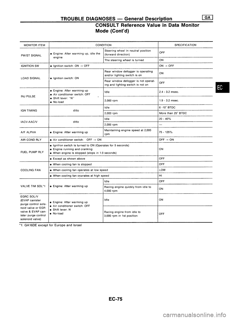
CONSULT Reference ValueinData Monitor
Mode (Cont'd)
MONITOR ITEM CONDITION
SPECIFICATION
Steering wheelinneutral position
OFF
PW/ST SIGNAL •
Engine: Afterwarming up.idle the
(forward direction)
engine Thesteering wheelisturned ON
IGNITION SW •
Ignition switch:ON
-->
OFF ON
-->
OFF
Rear window defogger isoperating
ON
and/or lighting switchison
LOAD SIGNAL •
Ignition switch:ON
Rearwindow defogger isnot operat-
OFF
ing and lighting switchisnot on
• Engine: Afterwarming up
Idle 2.4
-3.2 msec.
INJ PULSE •
Air conditioner switch:OFF
• Shift lever: "N"
.
• No-load 2.000
rpm 1.9
-3.2 msec.
Idle 6
_10' BTDC
IGN TIMING ditto
2.000rpm More
than25'BTDC
Idle 20-40%
IACV-AACIV ditto
2.000rpm
-
A/F ALPHA •
Engine: Afterwarming up Maintaining
enginespeedat2.000
75-125%
rpm
AIR COND RLY •
Air conditioner switch:OFF
-->
ON OFF
-->
ON
• Ignition switchisturned toON (Operates for5seconds)
• Engine running andcranking ON
FUEL PUMP RLY
•When engine isstopped (stopsin1.0 seconds)
• Except asshown above OFF
• When cooling fanisstopped OFF
COOLING FAN •
When cooling fanoperates atlow speed LOW
• When cooling fano!Jerates athigh speed HI
Idle OFF
VALVE TIMSOL'1 •Engine: Afterwarming up
Racingenginequickly fromidleto
4.000 rpm ON
EGRC SOLIV
(EVAP canister Idle
ON
purge control sole-•
Engine: Afterwarming up
• Air conditioner switch:OFF
noid valve orEGR
•Shift lever: N
valve
&
EVAP can-
•No-load Racing
enginefromidleto
ister purge control
3.000rpmin1st position OFF
solenoid valve)
*1: GA16DE exceptforEurope andIsrael
EC-75
•
Page 801 of 1701
TROUBLEDIAGNOSES -General Description ~
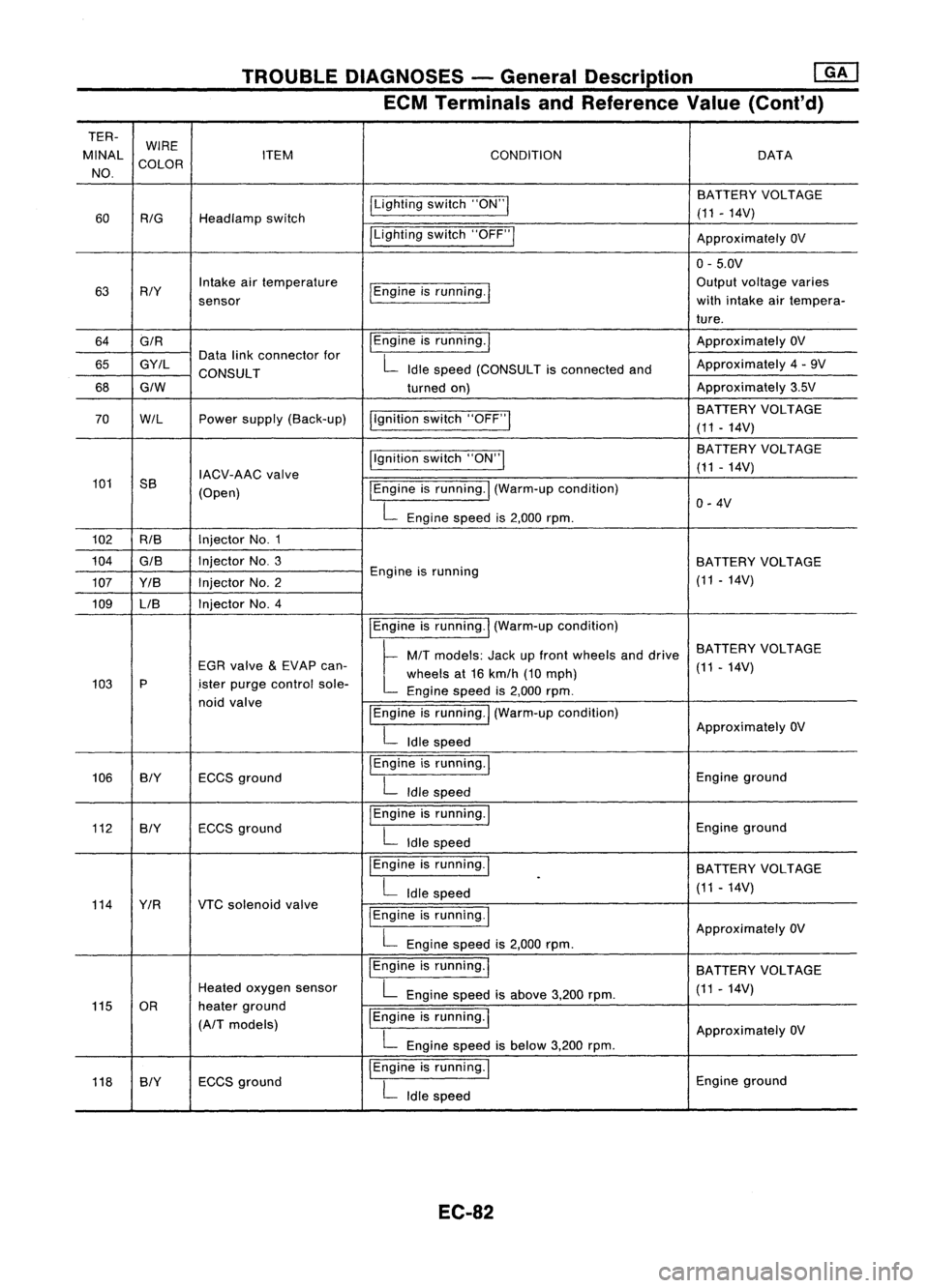
ECM Terminals andReference Value(Conl'd)
TER- WIRE
MINAL COLOR ITEM
CONDITION DATA
NO.
ILightingswitch"ON"I BATTERY
VOLTAGE
60
RIG
Headlamp switch (11
-14V)
ILighting switch"OFF"I
ApproximatelyOV
0- 5.0V
63 RIY Intake
airtemperature
I
Engine isrunning.
I
Output
voltage varies
sensor with
intake airtempera-
ture.
64 GIR
I
Engine isrunning.
I
Approximately
OV
65 GY/L Data
linkconnector for
L
Idle speed (CONSULT isconnected andApproximately
4-9V
CONSULT
68
GIW
turnedon) Approximately
3.5V
I,gnition switch"OFF"
I
BATTERY
VOLTAGE
70
W/L
Powersupply (Back-up)
(11-14V)
Ilgnition switch"ON"I BA
TTERY VOLTAGE
IACV-AAC valve (11
-14V)
101 SS
(Open)
I
Engine isrunning.
I
(Warm-up condition)
L
Engine speedis2,000 rpm. 0-
4V
102 RIB Injector
No.1
104
GIS
InjectorNo.3
BATTERYVOLTAGE
107 YIB InjectorNo.2 Engine
isrunning
(11-14V)
109 LIB Injector
No.4
IEngineisrunning.
I
(Warm-up condition)
~ MIT
models: Jackupfront wheels anddrive BATTERY
VOLTAGE
EGR valve
&
EVAP can-
L
wheels at16 kmlh (10mph) (11
-14V)
103 P
.isterpurge control sole-
Enginespeedis2,000 rpm.
noid valve
IEngineisrunning.
I
(Warm-up condition)
L
Idle speed Approximately
OV
106 BIY ECCSground
I
Engine isrunning.
I
Engineground
L
Idle speed
112 BIY ECCS
ground
I
Engine isrunning.
I
Engineground
L
Idle speed
I Engine isrunning.
I
BATTERYVOLTAGE
L
Idle speed
.
(11-14V)
114 YIR VTCsolenoid valve
I
Engine isrunning.
I
L
Engine speedis2,000 rpm. Approximately
OV
IEngine isrunning.
I
BATTERYVOLTAGE
Heated oxygen sensor
L
Engine speedisabove 3,200rpm. (11
-14V)
115 OR heaterground
IEngine isrunning.
I
(A/T models)
ApproximatelyOV
L
Engine speedisbelow 3,200rpm.
118 SlY ECCS
ground
I
Engine isrunning.
I
Engineground
L
Idle speed
EC-82
Page 803 of 1701
TROUBLEDIAGNOSES -General Description
rnJ
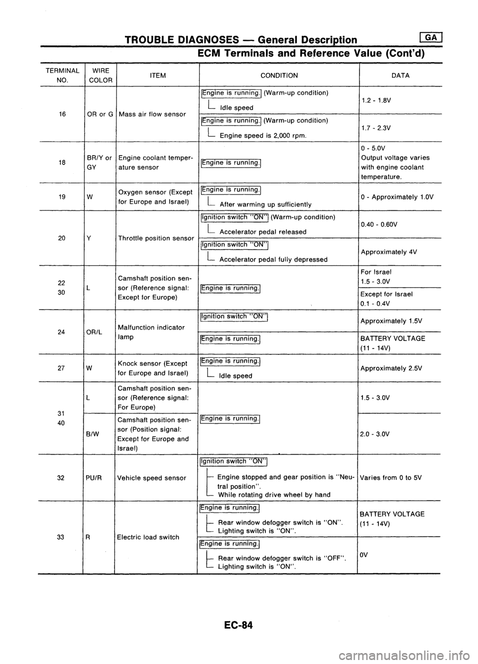
ECM Terminals andReference Value(Cont'd)
TERMINAL WIRE
CONDITION
NO. COLOR ITEM
DATA
IEngine isrunning./ (Warm-up condition)
1.2-1.8V
L
Idle speed
16 ORorG Mass airflow sensor
IEngineisrunning.1 (Warm-up condition)
1.7-2.3V
L
Engine speedis2,000 rpm.
0-5.0V
18 BR/Yor
Enginecoolant temper-
IEngineisrunning.' Output
voltage varies
GY aturesensor with
engine coolant
temperature.
19 W Oxygen
sensor(Except IEngine
isrunning.1
o-
Approximately 1.0V
for Europe andIsrael)
L
After warming upsufficiently
Ilgnition switch"ON"I(Warm-up condition)
0.40-0.60V
L
Accelerator pedalreleased
20 Y Throttlepositionsensor
jlgnitionswitch"ON"I
L
Accelerator pedalfullydepressed Approximately
4V
For Israel
22 Camshaft
positionsen-
1.5-3.0V
30 L
sor(Reference signal:
IEngineisrunning.1
Except forEurope) Except
forIsrael
0.1 -0.4V
Ilgnition switch"ON'"
Approximately1.5V
24 ORIL Malfunction
indicator
lamp IEngineisrunning.1 BATIERY
VOLTAGE
(11 -14V)
27 W Knock
sensor (Except IEngine
isrunning.1
Approximately2.5V
for Europe andIsrael)
L
Idle speed
Camshaft positionsen-
L sor(Reference signal: 1.5-3.0V
For Europe)
31 IEngineisrunning.1
40 Camshaft
positionsen-
B/W
sor
(Position signal:
2.0-3.0V
Except forEurope and
Israel)
Ilgnitionswitch"ON"I
32 PUIR Vehiclespeedsensor
t
Eog'oe stopped aodgea, posit;oo
'S
"Neu- Variesfrom0to 5V
tral position".
While rotating drivewheel byhand
IEngine isrunning.1
BATIERY VOLTAGE
t
Rear window defogger switchis"ON".
(11-14V)
Electric loadswitch Lighting
switchis"ON".
33 R
IEngineisrunning.1
t
Rear window defogger switchis"OFF". OV
Lighting switchis"ON".
EC-84
Page 805 of 1701
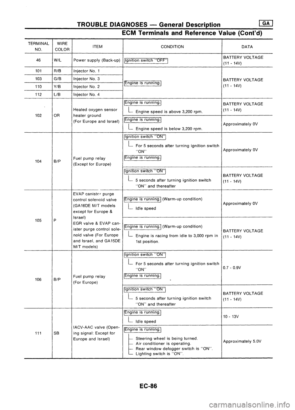
TROUBLEDIAGNOSES -General Description
mJ
ECM Terminals andReference Value(Cont'd)
TERMINAL WIRE
NO. COLOR ITEM
CONDITION DATA
46 WIL Powersupply (Back-up)
Ilgnitionswitch"OFF'" BA
TTERY VOLTAGE
(11 -14V)
101 RIB InjectorNo.1
103
GIB
InjectorNo.3
BATTERYVOLTAGE
110 Y/B InjectorNO.2 IEngine
isrunning./
(11-14V)
112 LIB Injector
NO.4
IEngineisrunning.1
BATTERY VOLTAGE
Heated oxygen sensor
L
Engine speedisabove 3,200rpm. (11
-14V)
102 OR heaterground
(For Europe andIsrael) IEngine
isrunning.1
ApproximatelyOV
L
Engine speedisbelow 3,200rpm.
jlgnition switch"ON"I
L
For 5seconds afterturning ignition switch
"ON" Approximately
OV
104 B/P Fuel
pump relay /Engine
isrunning.1
(Except forEurope)
Ilgnitionswitch"ON"I
BATTERYVOLTAGE
L
5seconds afterturning ignition switch
(11-14V)
"ON" andthereafter
EVAP canister purge
control solenoid valveIEngine
isrunning.1 (Warm-up condition)
(GA16DE
MIT
models
L
Idle speed Approximately
OV
except forEurope
&
105 P Israel)
EGR valve
&
EVAP can-
ister purge control sole-IEngine
isrunning.1 (Warm-up condition)
BATTERYVOLTAGE
noid valve (ForEurope
L
Engine isracing fromidleto3,000 rpmin
(11-14V)
and Israel, andGA15DE
1st position.
MIT
models)
jlgnitionswitch"ON"I
L
For 5seconds afterturning ignition switch
"ON" 0.7
-0.9V
106 SIP Fuel
pump relay IEngine
isrunning.1
(For Europe)
-
Ilgnition switch"ON"I
BATTERYVOLTAGE
L
5seconds afterturning ignition switch
(11-14V)
"ON" andthereafter
IEngine isrunning.1
10-13V
L
Idle speed
IACV-AAC valve(Open-
IEngineisrunning.1
111 5B ingsignal: Exceptfor
Europe andIsrael)
l
51.."" wheel
t,
be'" I,med
Approximately5.0V
Air conditioner isoperating.
Rear window defogger switchis"ON".
Lighting switchis"ON".
EC-86
Page 806 of 1701
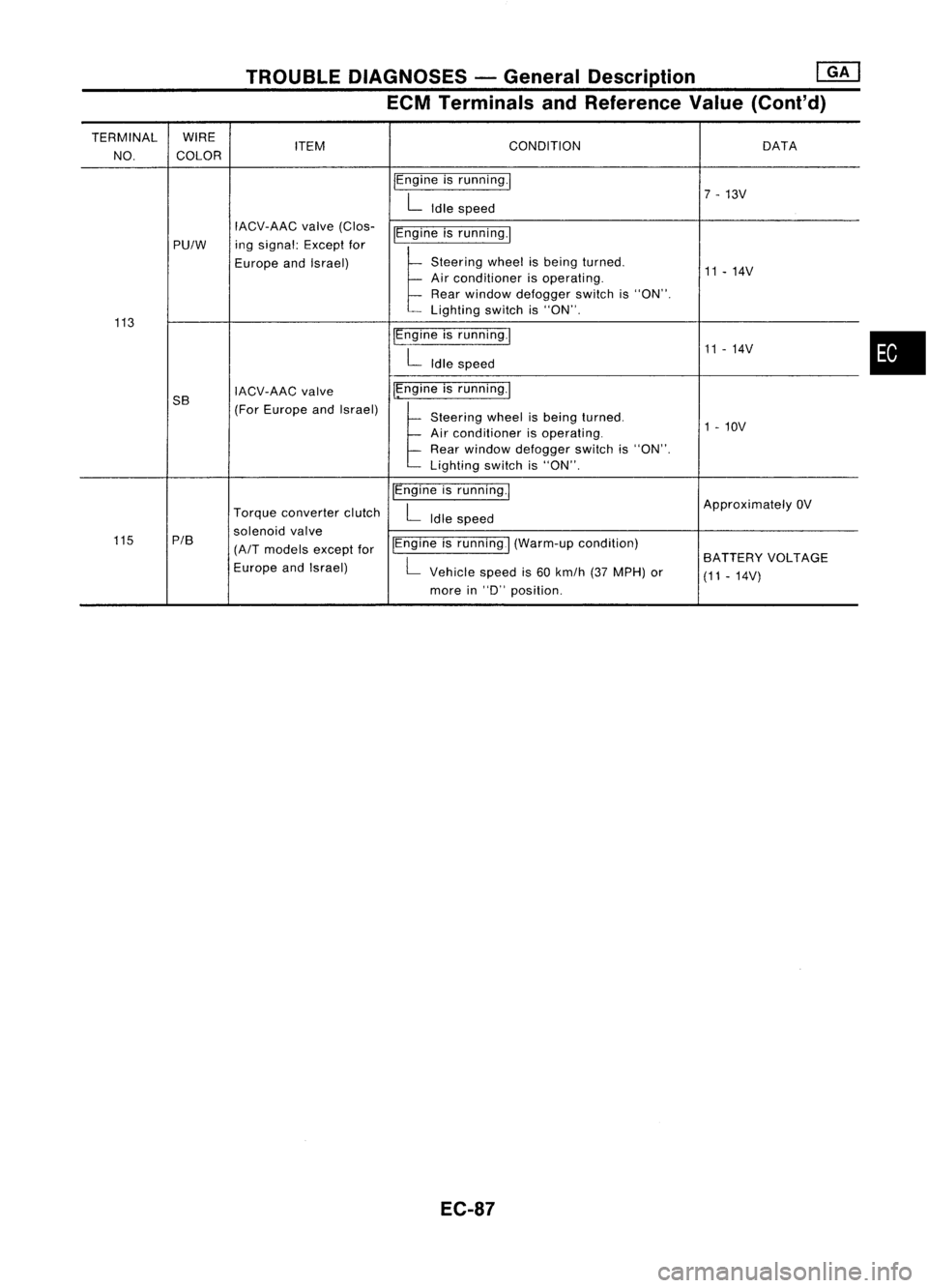
TROUBLEDIAGNOSES -General Description
[ill
ECM Terminals andReference Value(Cont'd)
TERMINAL WIRE
ITEM CONDITION
DATA
NO. COLOR
IEngineisrunning.1
7-13V
L
Idle speed
IACV-AAC valve(Clos-
~gineisrunning.1
PU/W ing
signal: Exceptfor
Europe andIsrael)
t
Stee,'", wheel',be'",t,med
11-14V
Air conditioner isoperating.
Rear window defogger switchis"ON".
Lighting switchis"ON".
113 IEngineisrunning.1
11-14V
L
Idle speed
5B IACV-AAC
valve I~ngine
isrunning.1
(For Europe andIsrael)
~Steee'", wheel"be'", t,med
Air conditioner isoperating. 1
-10V
Rear window defogger switchis"ON".
Lighting switchis"ON".
IEngine isrunning.1
ApproximatelyOV
Torque converter clutch
L
Idle speed
solenoid valve
115 P/B
(A/T
models exceptforIEngine
isrunning
I
(Warm-up condition)
L
BATTERY
VOLTAGE
Europe andIsrael)
Vehiclespeedis60 km/h (37MPH) or
(11-14V)
more in
"0"
position.
EC-87
•
Page 813 of 1701
TROUBLEDIAGNOSIS FORDTC11
Light emitting
diode
Wave
forming circuit
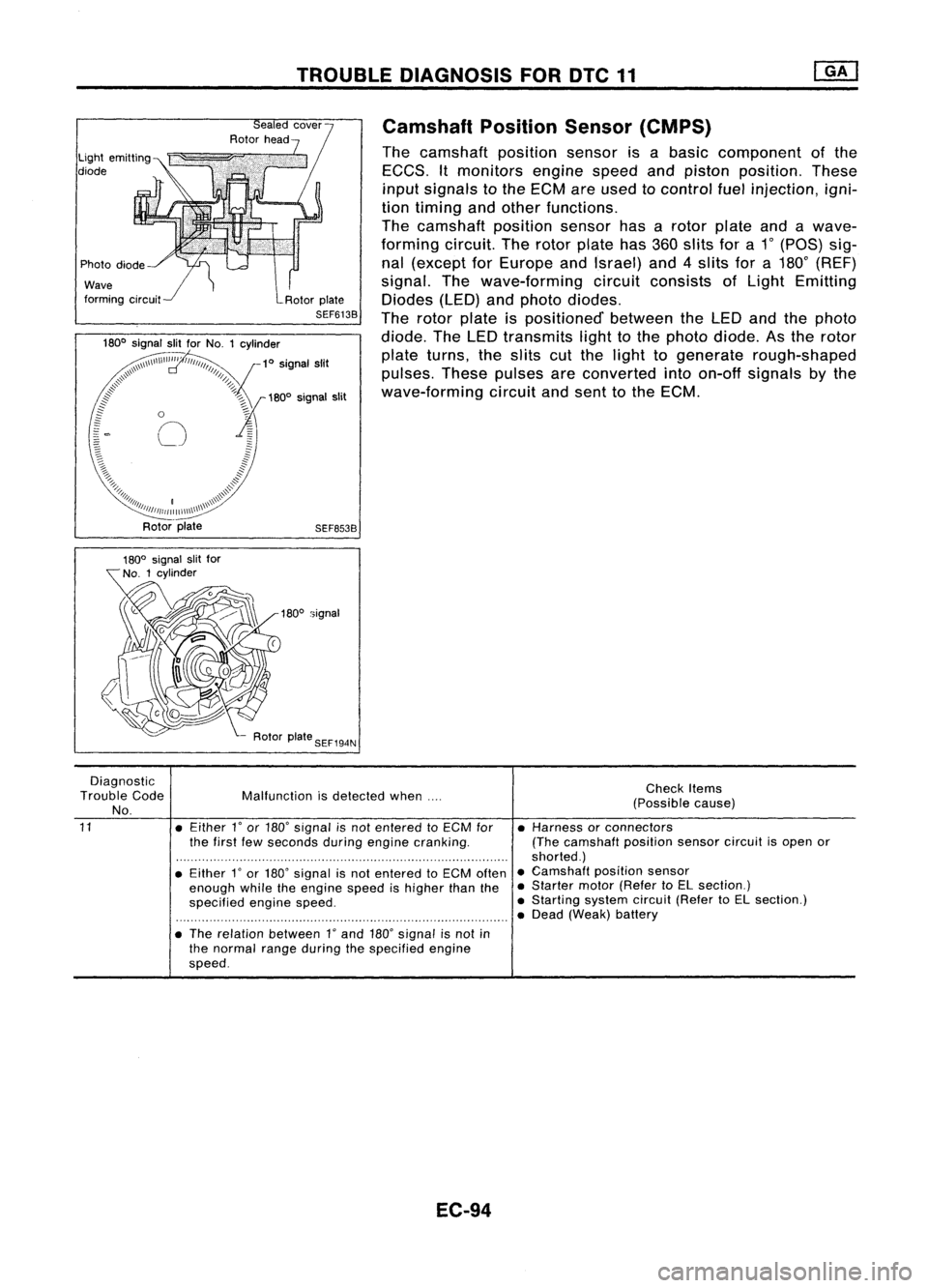
Camshaft
PositionSensor(CMPS)
The camshaft positionsensorisabasic component ofthe
EGGS. Itmonitors enginespeedandpiston position. These
input signals tothe EGM areused tocontrol fuelinjection, igni-
tion timing andother functions.
The camshaft positionsensorhasarotor plate andawave-
forming circuit.Therotor plate has360slits fora1
0
(paS) sig-
nal (except forEurope andIsrael) and4slits fora180
0
(REF)
signal. Thewave-forming circuitconsists ofLight Emitting
Diodes (LED)andphoto diodes.
The rotor plate ispositioned' betweentheLED andthephoto
diode. TheLED transmits lighttothe photo diode. Asthe rotor
plate turns, theslits cutthe light togenerate rough-shaped
pulses. Thesepulses areconverted intoon-off signals bythe
wave-forming circuitandsent tothe EGM.
SEF653B
180
0
signal
Diagnostic
Trouble Code
No.
11
Malfunction
isdetected when....
• Either
l'
or 180' signal isnot entered toECM for
the first fewseconds duringengine cranking.
• Either
l'
or 180' signal isnot entered toECM often
enough whiletheengine speedishigher thanthe
specified enginespeed.
• The relation between
l'
and 180'signal isnot in
the normal rangeduring thespecified engine
speed.
EC-94
Check
Items
(Possible cause)
• Harness orconnectors
(The camshaft positionsensorcircuitisopen or
shorted.)
• Camshaft positionsensor
• Starter motor(Refer toEL section.)
• Starting systemcircuit(RefertoEL section.)
• Dead (Weak) battery
Page 875 of 1701
TROUBLEDIAGNOSIS FORNON-DETECTABLE ITEMS
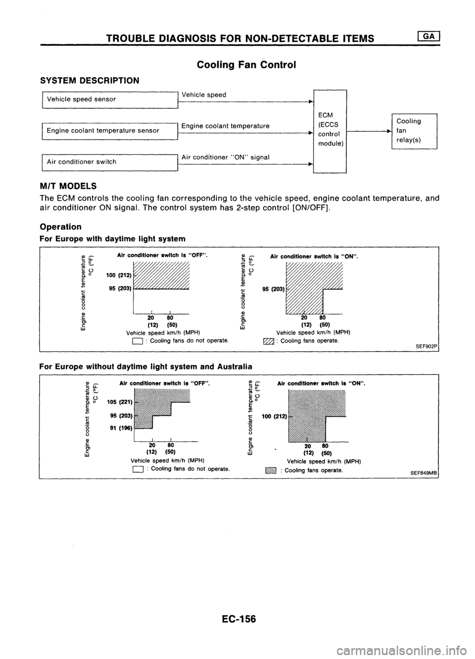
Cooling FanControl
SYSTEM DESCRIPTION
Vehicle speedsensor
Engine coolant temperature sensor
Air conditioner switch Vehicle
speed
Engine coolant temperature
Air conditioner "ON"signal
EGM
(EGGS
control
module) Gooling
fan relay(s)
MIT MODELS
The ECM controls thecooling fancorresponding tothe vehicle speed,engine coolant temperature, and
air conditioner ONsignal. Thecontrol system has2-step control [ON/OFF].
Operation
For Europe withdaytime lightsystem
E~
::J
0
~Z;
2i
o
E
~
~
'0
o
o
Gl
c
'0>
c
w
Air
conditioner switchIs"OFF".
/,
100 (212)
95 (203)
rr
20 80
(12) (50)
Vehicle speedkm/h(MPH)
D :
Cooling fansdonot operate.
~
iL
Airconditioner switchIs"ON".
~ ~ 11'l1/1~~~
:v
() /'/"
0.
0
E
~
!
95(203)
.~ 2080
ill
(12)(50)
Vehicle speedkm/h(MPH)
EZ2l :
Cooling fansoperate.
SEF902P
For Europe withoutdaytime lightsystem andAustralia
Gl_
2~
.,
-
:v ()
0.0
E
~
~
'0
o
o
Gl
c
'0>
c
w
Air
conditioner switchIs"OFF",
105 (221)
95 (203)
91 (196)
2080
(12) (50)
Vehicle speedkm/h(MPH)
D :
Cooling fansdonot operate.
Air
conditioner switchIs"ON",
100 (212)
2080
(12) (50)
Vehicle speedkm/h(MPH)
~ :Cooling fansoperate.
SEF649MB
EC-156