Page 598 of 1701
HORN,CIGARETTE LIGHTERANDCLOCK
Wiring Diagram -HORN -
LHD MODELS
EL-HORN-01
HORN
SWITCH
SPIRAL
CABLE
Models
without
air bagsystem
Models withdual
air bagsystem
Models withsingle
air bagsystem
8 *2
AIR BAG
DIAGNOSIS
SENSOR
UNIT
.......
_-.",.
RE-
LEASED
@:
@:
@:
HORN
SWITCH
SPIRAL
CABLE
em
'---"
RE-
LEASED
G/Y
m~
BATTERY
]
10A RefertoEL-POWER.
1421
G/B
g
2
HORN
~ RELAY
~1bjJl@
G G/Y
I----,O'----O~:------I
AN
!
~ G/Y
G /Y
r:::!::.
11tJ1~
11711
G/Y
......,~
I!:i=ll@
G/Y
~
T'---I
G G
QJ1 QJ1
HORN HORN
(LOW) (HIGH)
~ ~
ffim
[ill]
W
@
W
I:I[Q:TI:ICID
~W
DIDdZl
~BR
Refer
tolast page
(Foldout page).
FI ~ ~
(ffiJ)
L!J
B'B 'B
~*1
c:IIJgI
B
~*2
~W
HEL132
EL-226
Page 599 of 1701
HORN,CI(;ARETTE LIGHTERANDCLOCK
Wiring Diagram -HORN -(Cont'd)
EL-HORN-02
•
FUSE
Referto
BLOCK EL-POWER.
(JIB)
~
Refer tolast page
(Foldout page).
COMBINATION
METER
@
~
7.5A
1241
~
BIR
P
IF!4il
BIR
!
@)
OIGITAL
CLOCK
15A
[]Q]
CLOCK ILLUMI-
NATION
L
~
~ B
•
CIGARETTE
LIGHTER SOCKET
@
15A
[TI]
r-----------------------------------,
1ITl~
[]] B
@:
Withtachometer
@:
Without tachometer
*3"'@ 34
@
5
*4 ... @28
'@
6
*5' ..@29
'@10
*6"'@ 9
'@31
,
I
N;.21
OR/B
I
CIGARETTE OR/B
LIGHTER ~
~ 10-----.:
~B
l-,
I
B B
~1
ffi
JOINT
CONNECTOR-1
~
Ibi=Jl
B
I
f,
B B
! !
(M28) (M68)
L ~
IIIIIillIITillI
@
~BR
HEL133
EL-227
Page 600 of 1701
HORN,CIGARETTE LIGHTERANDCLOCK
Wiring Diagram -HORN -(ConI' d)
RHO
MODELS
EL-HORN-03
HORN
SWITCH
SPIRAL
CABLE
Models
without
air bagsystem
Models withdual
air bagsystem
Models withsingle
air bagsystem
B *2
AIR BAG
DIAGNOSIS
SENSOR
UNIT
.......
_-"
RE-
LEASED
@:
@:
@:
HORN
SWITCH
SPIRAL
CABLE
ill)
......
_-"
RE-
LEASED
G/Y
m
G/B
g
2
HORN
~ RELAY
~4=HID
G G/Y
I----IO----.O~ ..
------I
AN. G/Y
G/Y ~
~~ Ifill
I~I
G/Y
1~IU6~
G/Y
rn
'---I
G G
QJ1 QJ1
HORN HORN
(LOW) (HIGH)
m rn
mID
[ill]
W
@
W
~
ill)
DID"JZl
108)
~W ~BR
Refer
tolast page
(Fo ldout page).
F.1
rn m
l..!.J
B' B'B
~
*1
IT:I::illl
8
~*2
~W
HEL134
EL-228
Page 601 of 1701
HORN,CIGARETTE LIGHTERANDCLOCK
Wiring Diagram -HORN -(Cont'd)
EL-HORN-04
•
Refer
tolast page
(Foldout page).
FUSE
Referto
BLOCK EL-POWER.
(JIB)
([@
COMBINATION
METER
~
7.5A
1241
~
B/R
@: For
Europe
@:
Except forEurope
@: With
tachometer
@:
Without tachometer
*3"'@ 34
@
5
*4 ... @
28
'
6
B/R
,
*5"'@ 29
10
1
*6"'@
9
'
31
,
*7"'@ B
@
BR/Y
,
DIGITAL
CLOCK
15A
[]Q]
CLOCK ILLUMI-
NATION
Toillumination
control SWitch
-------II-BR/Y+
(Viajoint
connector-5)
(Refer toEL-ILL.)
CIGARETTE
LIGHTER
SOCKET
~
15A
mJ
r-----------------------------------,
[[il~
rn
B
CIGARETTE
LIGHTER
~ 10-----,- ,
~ B
L, ~
~o.:i
JOINT
CONNECTOR-1
~
~ B
I
" n
B
BBB
1
!..J
1
(M28) (M60) (M68)
L ~
I1IIIIIillIillI ~
~BR
HEL135
EL-229
Page 602 of 1701

REARWINDOW DEFOGGER ANDDOOR MIRROR DEFOGGER
System Description (Formodels withdaytime
light system)
For models withoutdaytime lightsystem, refertowiring diagrams, EL-233and234.
The rear window anddoor mirror defogger systemiscontrolled bythe rear window defogger timer.
Power issupplied atall times
• torear window defogger relayterminal
@
• through 20Afuse (No.[[],located inthe fuse block).
With theignition switchinthe ACC orON position, powerissupplied
• tomirror defogger relayterminal
@
• through 10Afuse (No.
InJ,
located inthe fuse block).
With theignition switchinthe ONorSTART position, powerissupplied
• torear window defogger relayterminal
CD
• through 10Afuse (No.
[2ID,
located inthe fuse block)
• torear window defogger timerterminal
CD
• through 7.5Afuse(No.[[],located inthe fuse block).
Ground issupplied
• torear window defogger switchterminal
@
and
• torear window defogger timerterminal
@
• through bodygrounds
@
and
@ID.
Operation
The ignition switchmustbeinthe ONorSTART position fordefogger operation.
With therear window defogger switchinthe ONposition andforapproximately 12-16 minutes afterthe
rear window defogger switchhasturned toOFF from ON,ground issupplied
• through terminal
CD
ofthe rear window defogger switch
• torear window defogger timerterminal
@.
Terminal
@
ofthe rear window defogger timerthensupplies groundtorear window defogger relay
terminal
@.
With power andground supplied, rearwindow defogger relayisenergized.
For rear window defogger system,powerissupplied
• through terminal
CID
ofthe rear window defogger relay
• tocondenser terminal
CD
• through terminal
@
ofthe condenser
• tothe rear window defogger terminal
CD.
For mirror defogger system,powerissupplied
• through terminal
CID
ofthe rear window defogger relay
• tomirror defogger relayterminal
CD.
Ground issupplied
• through bodygrounds
@
and
@ID
• tomirror defogger relayterminal
@.
With power andground supplied, mirrordefogger relayisenergized.
• through mirrordefogger relayterminal
CID
• toeac
r
doormirror defogger terminal
@.
Ground issupplied
• torear window defogger terminal
@
• through bodyground
and
• toeach doormirror defogger terminal
CD
• through bodygrounds
@
and
@ID.
With power andground supplied, eachdefogger filamentheatsanddefogs therear window anddoor
mirror.
When thesystem isactivated, therear window defogger indicatorilluminates inthe rear window defog-
ger switch.
Power issupplied
• toterminal
CID
ofthe rear window defogger switch
• from terminal
CID
ofthe rear window defogger relay.
Terminal
@
ofthe rear window defogger switchisgrounded throughbodygrounds
@
and
@.
EL-230
Page 603 of 1701
REARWINDOW DEFOGGER ANDDOOR MIRROR DEFOGGER
Wiring Diagram -DEF -
LHD MODELS WITHDAYTIME LIGHTSYSTEM
EL-DEF-01
Gasoline engine
Diesel engine
@:
@) :
Refer
toEL-POWER.
FUSE
BLOCK
(JIB)
CM15)
~06)
CE120)
20A
W
II
P•2
1
LIB
! ~
~¥~~OW
I
J
12~r~~GER
~ 1!:iJI~:@
G/R L/R~:
@
JOINT
~ ~ ~ CONNECTOR-2
I~~-----~ ~
G/R
L/R ~
1. L/R-[J
Et
L/R - L/R~} Nextpage
!di
L/R - L/R~
~ ~~
1-------
Lf
I
RIG
+
ToEL-ILL
G/B
L/R
RIG
B
n1il ~
n=tD (!J1
~f} ~¥~~OW INDILL ~¥~~OW JOINT
SW DEFOGGER DEFOGGERCONNECTOR-3
TIMER OFF SWITCH~
GND ~ ~
11111
11211 9F
~ ~t
B.
B BBB
I--ll-l-l 11
(M"2B)
G/R
~
OUT PUT
G
IftlJ
IGN
+
~:@
2 1
5
~:@
L
r1ITr1l~
ITITITJ
GY
ITIIIII:illTIIi
~
~BR
Refer
tolast page •
(Foldout page).
F.ffi1
tm::l
W
fffffi~
rn:mrn
W
HEL136
EL-231
Page 605 of 1701
REARWINDOW DEFOGGER ANDDOOR MIRROR DEFOGGER
Wiring Diagram -DEF -(Conl'd)
LHD MODELS WITHOUT DAYTIMELIGHTSYSTEM
EL-DEF-03
•
Refer
tolast page
(Foldout page).
~
L/R~
... B
~1
B
@QD
=
r:
j
:'I~
CONDENSER
REAR
WINDOW
DEFOGGER
lbjJJ~
B
!-
~
-
~:
Sedanmodels
~ :Hatchback models
~----------------~
: F.=1
@
,(0104) B~ :
'WB B@B
I
I I
L ~
filllaID
@g]
W
-----------------
RIG.
ToEL-ILL
r1TTI1l@
IT1IITI
GY
~~g~K
RefertoEL-POWER.
(JIB)
~
i
L/R JOINT
. CONNECTOR-2
[¥
1 ~
REAR
~~~gg~ER ~L/R
---I
SWITCH L/R
~ II
J
II
I"TI'A\
~ ~ ~~
~ ~ L/R ICIJI
(]I)
L/R B
B
I
t
LIR
Ll:!
~!
s
I
L/R
B
IcIJlm~~
rn~
I
L/R~
JOINT
L~
CONNECTOR-3 L/R~
II UI ...B~
~ B~
=
I
m~
CONOENsrn
REAR
WINDOW
tt
ll
DEFOGGER
lbjJJ~
B
-!- -!-
1
~ (868)
ffiill1~
~ W
I1III1IIIIIIIII ~
~BR r-------------.,
: F.=1~
B~:
I
W
B
@
B
I
I I
L
j
HEL138
EL-233
Page 608 of 1701

REARWINDOW DEFOGGER ANDDOOR MIRROR DEFOGGER
Filament Repair
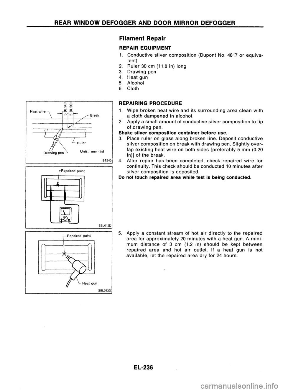
REPAIR EQUIPMENT
1. Conductive silvercomposition (DupontNo.4817 orequiva-
lent)
2. Ruler 30cm (11.8 in)long
3. Drawing pen
4. Heat gun
5. Alcohol
6. Cloth
Unit: mm(in)
REPAIRING
PROCEDURE
1. Wipe broken heatwire anditssurrounding areaclean with
a cloth dampened inalcohol.
2. Apply asmall amount ofconductive silvercomposition totip
of drawing pen.
Shake silvercomposition containerbeforeuse.
3. Place ruleronglass along broken line.Deposit conductive
silver composition onbreak withdrawing pen.Slightly over-
lap existing heatwire onboth sides [preferably 5mm (0.20
in)] ofthe break.
4. After repair hasbeen completed, checkrepaired wirefor
continuity. Thischeck should beconducted 10minutes after
silver composition isdeposited.
Do not touch repaired areawhile testisbeing conducted.
BE540
SEL012D
Break
R .d
epalre point
j
IrJ
t..@.!.
-
--
Heat
wire
Repairedpoint
5.
Apply aconstant streamofhot airdirectly tothe repaired
area forapproximately 20minutes withaheat gun.Amini"-
mum distance of3cm (1.2 in)should bekept between
repaired areaandhotairoutlet. Ifa heat gunisnot
available, letthe repaired areadryfor24hours.
SEL013D
EL-236