Page 695 of 1701
AfTmodel
SFA730FRONT
AXLE
Drive Shaft(Coni' d)
4. Separate driveshaftfromknuckle byslightly tapping it.
If it is hard toremove, useapuller.
When removing driveshaft, cover bootswithshop towel to
prevent damage tothem.
Refer toFRONT AXLE-Wheel HubandKnuckle (FA-8).
5. Remove rightdrive shaftfromtransaxle.
6. Remove leftdrive shaftfromtransaxle.
-For MITmodels-
• Pry offdrive shaftfromtransaxle asshown atleft.
-For AITmodels-
• Insert screwdriver intotransaxle openingforright drive
shaft andstrike withahammer.
Be careful nottodamage pinionmateshaftandside gear.
FA-13
•
Page 702 of 1701
SFA800
r:r
1..--*
-Wheel bearing
lock nut
SFA130A
SFA4568
SFA4438
FRONT
AXLE
Drive Shaft(Cont'd)
Wheel side
1. Install bootandnew small bootband on
drive
shaft.
Cover driveshaftserration withtape soas not todamage boot
during installation.
2. Set joint assembly onto
drive
shaftbylightly tapping it.
Install jointassembly securely,ensuringmarkswhichwere
made during disassembly areproperly aligned.
3. Pack
drive
shaftwithspecified amountofgrease.
Specified amountofgrease:
ZF80 95g(3.35
oz)
ZF90 115-125
g
(4.06 .4.41 oz)
BF83 85.105g(3.00 -3.70 oz)
4. Make surethatboot isproperly installedonthe drive shaft
groove.
Set boot sothat itdoes notswell anddeform whenitslength
is
"L,".
Length
"L/':
ZF80 90.5-92.5 mm(3.563 -3.642 in)
ZF90 96-98 mm (3.78 -3.86 in)
BF83 94-96 mm (3.70 -3.78 in)
5. Lock newlarger andsmaller bootbands securely witha
suitable tool.
FA-20
Page 709 of 1701

View
from
B FRONT
SUSPENSION
Stabilizer Bar(Cont'd)
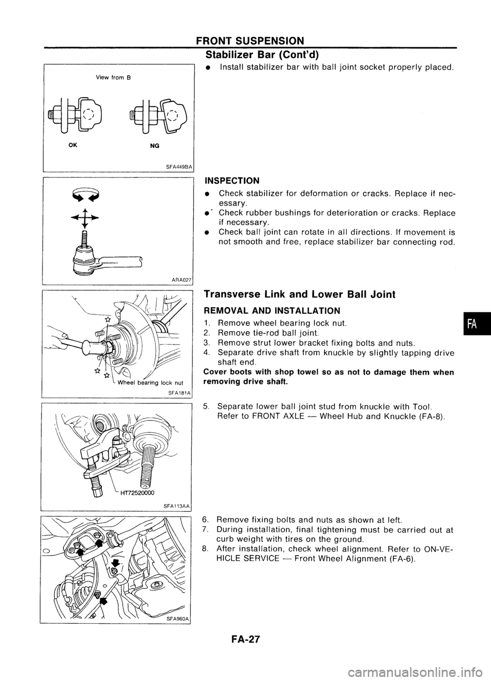
• Install stabilizer barwith balljoint socket properly placed.
OK NG
SFA449BA
ARA027 INSPECTION
• Check stabilizer fordeformation orcracks. Replace ifnec-
essary.
• Check rubber bushings fordeterioration orcracks. Replace
if necessary.
• Check balljoint canrotate inall directions. If
movement
is
not smooth andfree, replace stabilizer barconnecting rod.
SFA181A
SFA113AA Transverse
LinkandLower BallJoint
REMOVAL ANDINSTALLATION
1. Remove
wheelbearing locknut. •
2. Remove
tie-rodballjoint.
3. Remove
strutlower bracket fixingboltsandnuts.
4. Separate driveshaftfromknuckle byslightly tapping drive
shaft end.
Cover bootswithshop towel soas not todamage themwhen
removing driveshaft.
5. Separate lowerballjoint studfrom knuckle withTool.
Refer toFRONT AXLE-Wheel HubandKnuckle (FA-8).
6. Remove
fixingboltsandnuts asshown atleft.
7. During installation, finaltightening mustbecarried outat
curb weight withtires onthe ground.
8. After installation, checkwheel alignment. RefertoON-VE-
HICLE SERVICE -Front Wheel Alignment (FA-6).
FA-27
Page 723 of 1701
PRECAUTIONSANDPREPARATION
Special Service Tools
Tool number
Tool name Description Engine
application
SR GA
EG11140000
Ignition coiladapter
harness
KV10117100
Heated oxygen sensor
wrench
KV10114400
Oxygen sensorwrench
NT338
NT630
NT636
Measuring
enginespeed
Loosening ortightening
heated oxygen sensor
Loosening orlightening
heated oxygen sensor
a: 22 mm (0.87 in)
x
x
x
x
FOR CDENGINE VE-TYPE INJECTION PUMP
Adjusting deviceonvehicle
Tool number
Tool name Description
KV11229352
Measuring device
CD
KV11229350
Holder
@ KV11229360
Nut
@ KV11229370
Pin
@ KV11254410
Dial gauge
KV11102900
Pulley puller
NT570
NT647
EC-4
Measuring
setlength ofplunger spring
Removing injectionpumpsprocket
Page 727 of 1701

PRECAUTIONSANDPREPARATION
Engine Fuel
&
Emission ControlSystem
I
GA, SR
I
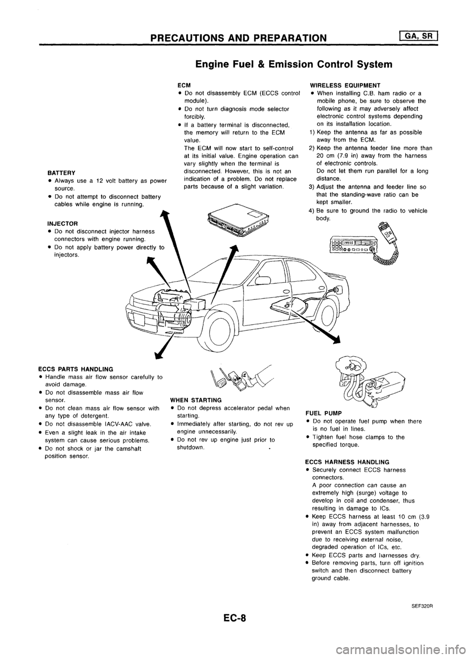
BATTERY • Always usea12 volt battery aspower
source.
• Do not attempt todisconnect battery
cables whileengine isrunning.
INJECTOR • Do not disconnect injectorharness
connectors withengine running.
• Do not apply battery powerdirectly to
injectors.
ECCS PARTS HANDLING
• Handle massairflow sensor carefully to
avoid damage.
• Do not disassemble massairflow
sensor.
• Do not clean massairflow sensor with
any type ofdetergent.
• Do not disassemble IACV-AACvalve.
• Even aslight leakinthe airintake
system cancause serious problems.
• Do not shock orjar the camshaft
position sensor. ECM
• Do not disassembly EGM(EGGS control
module).
• Do not turn diagnosis modeselector
forcibly.
• Ifabattery terminal isdisconnected,
the memory willreturn tothe ECM
value.
The ECM willnow start toself-control
at its initial value. Engine operation can
vary slightly whentheterminal is
disconnected. However,thisisnot an
indication ofaproblem. Donot replace
parts because ofaslight variation.
WHEN STARTING
• Do not depress accelerator pedalwhen
starting.
• Immediately afterstarting, donot revup
engine unnecessarily .
• Do not revupengine justprior to
shutdown.
EC-8 WIRELESS
EQUIPMENT
• When installing C.B.hamradio ora
mobile phone, besure toobserve the
following asitmay adversely affect
electronic controlsystems depending
on itsinstallation location.
1) Keep theantenna asfar aspossible
away fromtheEGM.
2) Keep theantenna feederlinemore than
20 em (7.9 in)away fromtheharness
of electronic controls.
Do not letthem runparallel foralong
distance.
3) Adjust theantenna andfeeder lineso
that thestanding-wave ratiocanbe
kept smaller.
4) Be sure toground theradio tovehicle
body.
FUEL PUMP
• Do not operate fuelpump whenthere
is no fuel inlines.
• Tighten fuelhose clamps tothe
specified torque.
ECCS HARNESS HANDLING
• Securely connectEGGSharness
connectors.
A poor connection cancause an
extremely high(surge) voltage to
develop incoil and condenser, thus
resulting indamage toICs .
• Keep ECGS harness atleast 10em (3.9
in) away fromadjacent harnesses, to
prevent anEGGS system malfunction
due toreceiving externalnoise,
degraded operation ofIGs, etc.
• Keep EGCS partsandharnesses dry.
• Before removing parts,turnoffignition
switch andthen disconnect battery
ground cable.
SEF320R
Page 742 of 1701

ENGINEANDEMISSION BASICCONTROL SYSTEMDESCRIPTION
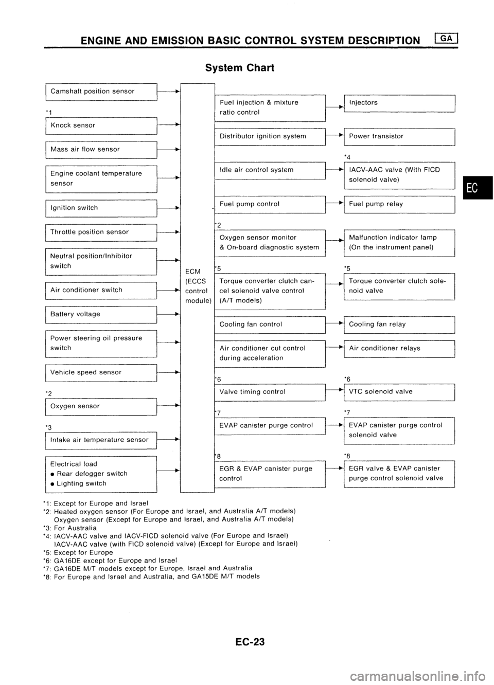
System Chart
I
Camshaft positionsensor
'1
Fuel
injection
&
mixture
ratio control Injectors
Knock sensor
Distributorignitionsystem Powertransistor
Mass airflow sensor
Engine coolant temperature
sensor
Ignition switch Idle
aircontrol system
Fuel pump control
*4
IACV-AAC valve(WithFICD
solenoid valve)
Fuel pump relay
•
'5
Throttle
positionsensor
Neutral positionllnhibitor
switch
Air conditioner switch ECM
(ECCS
control
module)
2
Oxygen sensormonitor
&
On-board diagnostic system
5
Torque converter clutchcan-
cel solenoid valvecontrol
(A/T models) Malfunction
indicatorlamp
(On theinstrument panel)
Torque converter clutchsole-
noid valve
VTC solenoid valve
*6
Air
conditioner relays
Cooling
fanrelay
EVAP canister purgecontrol
solenoid valve
Cooling
fancontrol
Air conditioner cutcontrol
during acceleration
Valve timing control
EVAP canister purgecontrol
7
6
Power
steering oilpressure
switch Battery
voltage
Intake airtemperature sensor
*3
I
Vehicle speedsensor
*2
I
Oxygen sensor
8
'8
Electrical load
• Rear defogger switch
• Lighting switch EGR
&
EVAP canister purge
control EGR
valve
&
EVAP canister
purge control solenoid valve
*1: Except forEurope andIsrael
*2: Heated oxygen sensor(ForEurope andIsrael, andAustralia A/Tmodels)
Oxygen sensor(Except forEurope andIsrael, andAustralia A/Tmodels)
*3: For Australia
*4: IACV-AAC valveandIACV-FICD solenoidvalve(ForEurope andIsrael)
IACV-AAC valve(withFICDsolenoid valve)(Except forEurope andIsrael)
'5: Except forEurope
*6: GA16DE exceptforEurope andIsrael
*7: GA16DE MITmodels exceptforEurope, IsraelandAustralia
*8: For Europe andIsrael andAustralia, andGA15DE MITmodels
EC-23
Page 749 of 1701

EVAPORATIVEEMISSIONSYSTEM
Inspection (Cont'd)
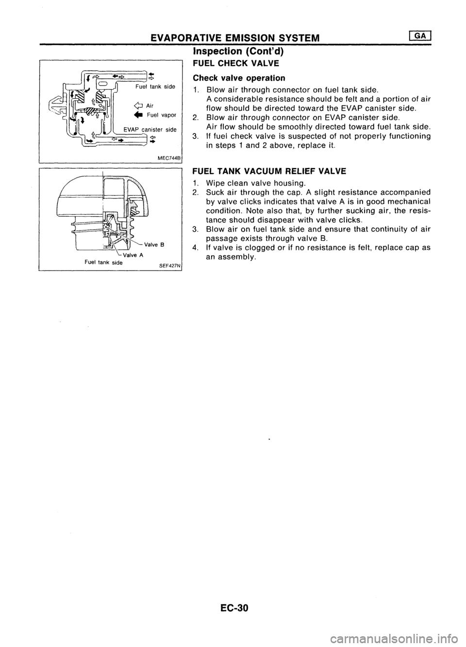
FUEL CHECK VALVE
~V""B
ValveA
Fuel tank side
..
"?
Fuel tankside
QAir
... Fuel vapor
EVAP canister side
..
MEC744B
SEF427N Check
valveoperation
1. Blow airthrough connector onfuel tank side.
A considerable resistanceshouldbefelt and aportion ofair
flow should bedirected towardtheEVAP canister side.
2. Blow airthrough connector onEVAP canister side.
Air flow should besmoothly directedtowardfueltank side.
3. Iffuel check valveissuspected ofnot properly functioning
in steps 1and 2above, replace
it.
FUEL TANK VACUUM RELIEFVALVE
1. Wipe clean valvehousing.
2. Suck airthrough thecap. Aslight resistance accompanied
by valve clicks indicates thatvalve Ais in good mechanical
condition. Notealsothat, byfurther sucking air,theresis-
tance should disappear withvalve clicks.
3. Blow aironfuel tank sideandensure thatcontinuity ofair
passage existsthrough valveB.
4. Ifvalve isclogged orifno resistance isfelt, replace capas
an assembly.
EC-30
Page 755 of 1701
ADJUSTING VALUE BASIC
SERVICE PROCEDURE @K]
Idle Speed/Ignition TiminglldleMixtureRatio
Adjustment (Cont'd)
Engine GA14DE,GA16DE
GA16DEGA16DE
models (ForEurope andIsrael) GA15DE
(ForAustralia) (Except
forEurope and
Israel, andAustralia)
MfT
(Without AfT
AfT AfTAfT
Transaxle (With
day-
daytime (in
"N"
MfT(in
"N" MfT(in"N" MfT(in
"N"
time light
lightsys- position)
position) position)position)
system) tem)
Base idle
speed 625::t50 625::t50 725::t50 580::t50
700::t50 625::t50
725::t50600::1:50 750::t50
(rpm)
Idle speed
800::t50 700::t50 800::t50630::t50 750::t50 675::t50 800::t50 650::1:50 800::t
50
(rpm)
Ignition timing 10::t2
10::t2
10::t2 6::t26::t2 8::t28::t210::t2 10::t2
CBTDC)
EC-36