Page 1159 of 1701
ENGINECOOLING SYSTEM
Water outlet
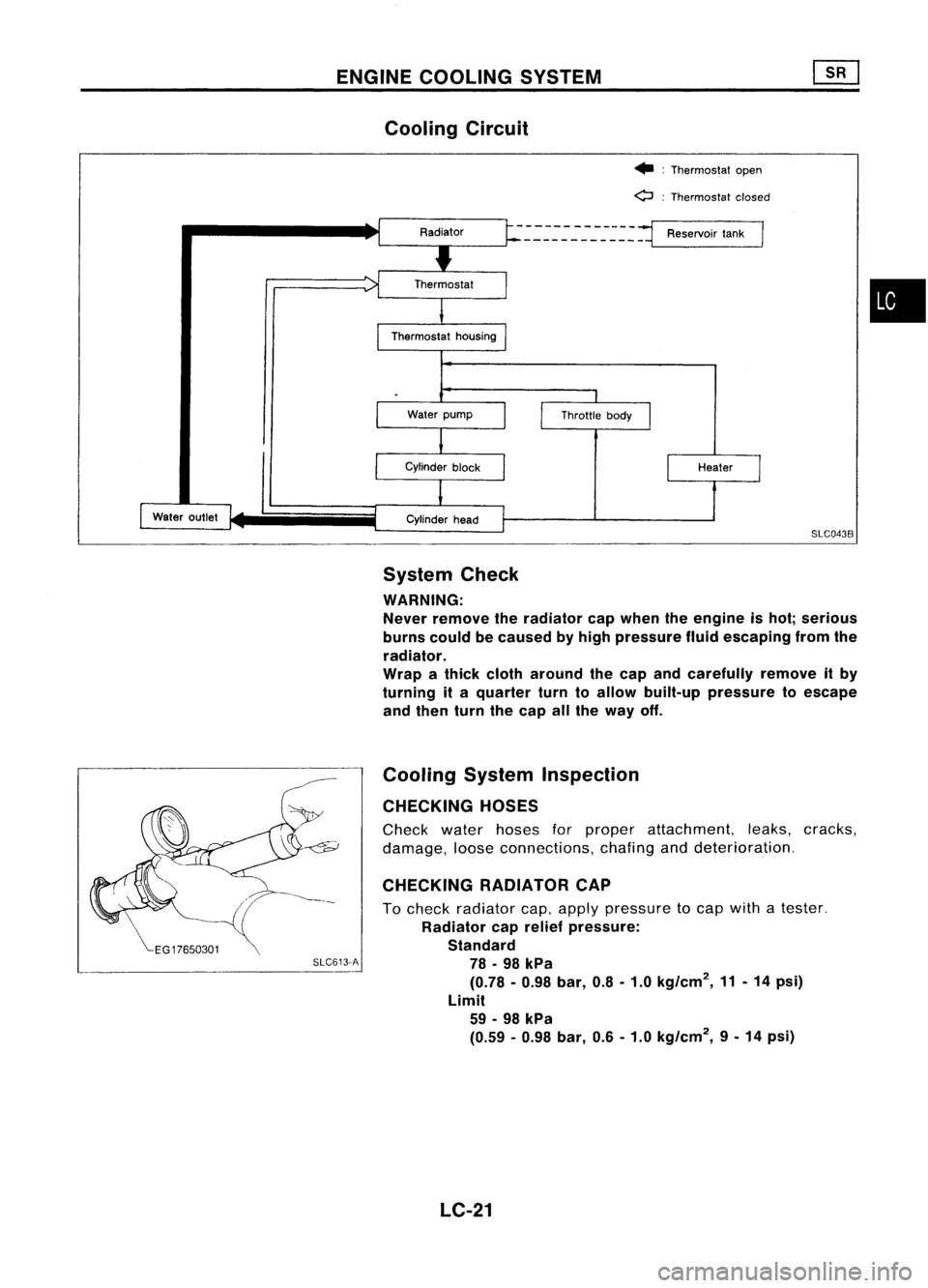
Cooling
Circuit
•:Thermostat open
o :
Thermostat closed
- ~.=-~:: --_-_-_-~ ~~
=1
Reservoir tank
I
SLC043B
System Check
WARNING: Never remove theradiator capwhen theengine ishot; serious
burns couldbecaused byhigh pressure fluidescaping fromthe
radiator.
Wrap athick cloth around thecap andcarefUlly removeitby
turning ita quarter turntoallow built-up pressure toescape
and then turnthecap allthe way off.
Cooling SystemInspection
CHECKING HOSES
Check waterhoses forproper attachment, leaks,cracks,
damage, looseconnections, chafinganddeterioration.
CHECKING RADIATORCAP
To check radiator cap,apply pressure tocap with atester.
Radiator caprelief pressure:
Standard
SLC613-A
78•98 kPa
(0.78 -0.98 bar,0.8-1.0 kg/cm
2,
11-14 psi)
Limit 59 -98 kPa
(0.59 -0.98 bar,0.6-1.0 kg/cm
2,
9-14 psi)
LC-21
•
Page 1165 of 1701
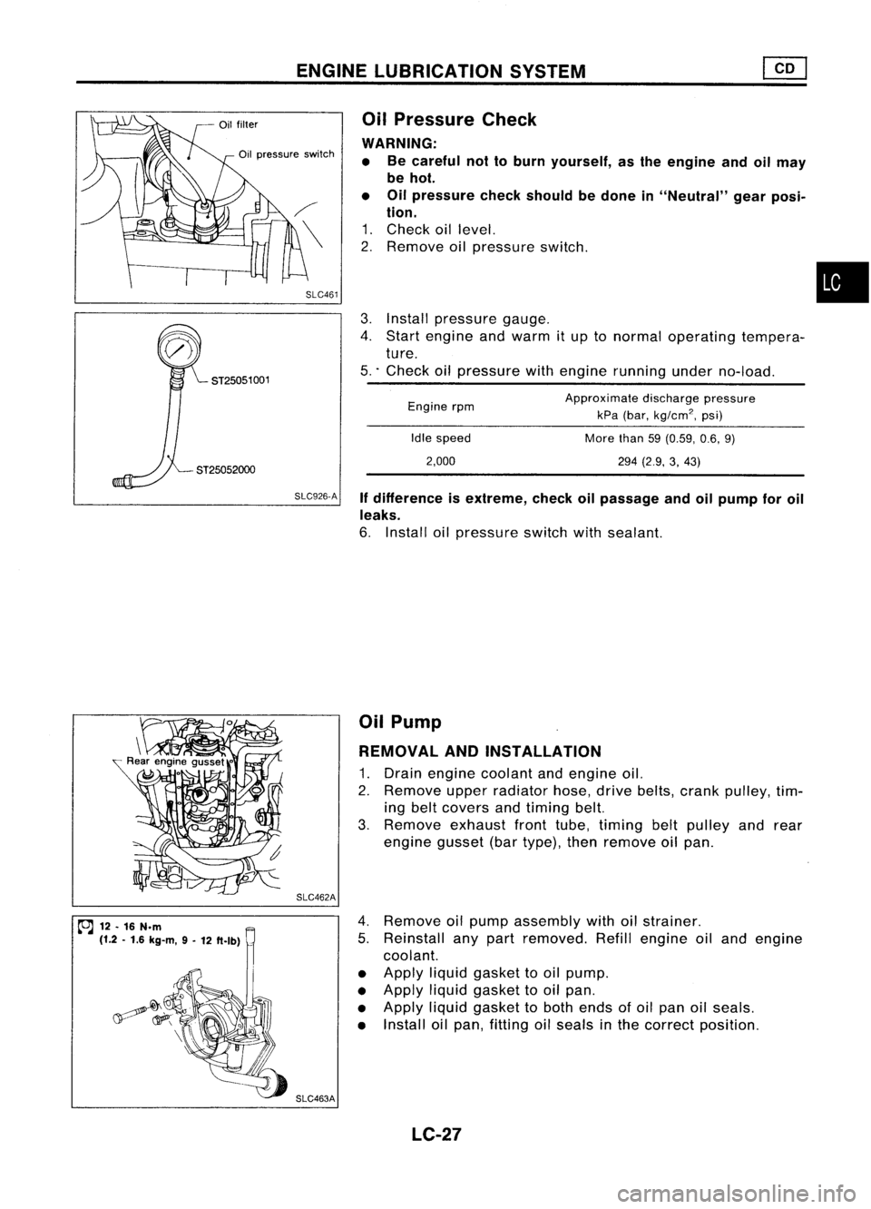
ENGINELUBRICATION SYSTEM
SLC926.A Ifdifference isextreme, checkoilpassage andoilpump foroil
leaks.
6. Install oilpressure switchwithsealant.
ST25052000
3.
Install pressure gauge.
4. Start engine andwarm itup tonormal operating tempera-
ture.
5 .. Check oilpressure withengine running underno-load.
•
Approximate dischargepressure
kPa (bar,
kg/cm
2,
psi)
More than59(0.59, 0.6,9)
294 (2.9, 3,43)
Idle
speed
2,000
Engine
rpm
Oil
Pressure Check
WARNING: • Becareful nottoburn yourself, asthe engine andoilmay
be hot.
• Oilpressure checkshould bedone in"Neutral" gearposi-
tion.
1. Check oillevel.
2. Remove oilpressure switch.
SLC461
Oil
pressure switch
ST25051 001
~ 12.16 N.m
(1.2 .1.6 kg-m, 9-
12 ft.lb) SLC462A
SLC463A Oil
Pump
REMOVAL ANDINSTAllATION
1. Drain engine coolant andengine oil.
2. Remove upperradiator hose,drivebelts, crank pulley, tim-
ing belt covers andtiming belt.
3. Remove exhaustfronttube, timing beltpulley andrear
engine gusset(bartype), thenremove oilpan.
4. Remove oilpump assembly withoilstrainer.
5. Reinstall anypart removed. Refillengine oiland engine
coolant.
• Apply liquidgasket tooil pump.
• Apply liquidgasket tooil pan.
• Apply liquidgasket toboth ends ofoil pan oilseals.
• Install oilpan, fitting oilseals inthe correct position.
LC-27
Page 1170 of 1701
ENGINECOOLING SYSTEM
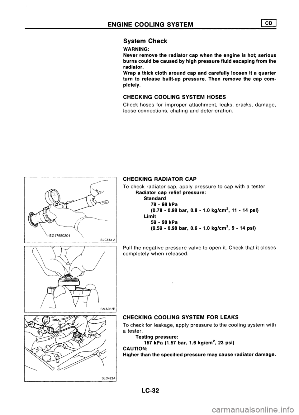
System Check
WARNING:
Never remove theradiator capwhen theengine ishot; serious
burns couldbecaused byhigh pressure fluidescaping fromthe
radiator.
Wrap athick cloth around capandcarefully loosenita quarter
turn torelease built-uppressure. Thenremove thecap com-
pletely.
CHECKING COOLINGSYSTEMHOSES
Check hosesforimproper attachment, leaks,cracks, damage,
loose connections, chafinganddeterioration.
CHECKING RADIATORCAP
To check radiator cap,apply pressure tocap with atester.
Radiator caprelief pressure:
Standard 78 -98 kPa
(0.78 -0.98 bar,0.8-1.0 kg/cm
2,
11-14 psi)
Limit 59 -98 kPa
(0.59 -0.98 bar, 0.6-1.0 kg/cm
2,
9-14 psi)
SLC613-A
Pullthenegative pressure valvetoopen
it.
Check thatitcloses
completely whenreleased.
CHECKING COOLINGSYSTEMFORLEAKS
To check forleakage, applypressure tothe cooling systemwith
a tester.
Testing pressure:
157 kPa (1.57 bar,1.6kg/cm
2,
23psi)
CAUTION:
Higher thanthespecified pressure maycause radiator damage.
SLC422A LC-32
Page 1177 of 1701
SLC904
CD
@
10~~103~ \
~' ENGINE
COOLING SYSTEM
I
GA, SR,CD
I
Radiator (Aluminum type)(Cont'd)
4. Caulk tankinspecified sequence withTool.
•
Keep toolperpendicular to
the radiator.
o
X
(Grip isinsufficient.)
SLC896
• Use pliers inthe locations whereToolcannot beused.
5. Make surethattherim iscompletely crimpeddown.
Standard height
"H":
8.0 -8.4 mm (0.315 -0.331 in)
6. Confirm thatthere isno leakage.
Refer toInspection.
INSPECTION
Apply pressure withTool.
Specified pressurevalue:
157 kPa (1.57 bar,1.6kg/cm
2,
23psi)
WARNING:
To prevent therisk ofthe hose coming undonewhileunder
pressure, securelyfastenitdown withahose clamp.
Attach ahose tothe oilcooler aswell.
(A
IT models only)
SLC933 LC-39
Page 1224 of 1701
ENGINEREMOVAL
WARNING:
a. Situate vehicle onaflat and solid surface.
b. Place chocks atfront andback ofrear wheels.
c. Donot remove engineuntilexhaust systemhascompletely
cooled off.
Otherwise, youmay burn yourself and/orfiremay break out
in fuel line.
d. For safety during subsequent steps,thetension ofwires
should beslackened againsttheengine.
e. Before disconnecting fuelhose, release fuelpressure from
fuel line.
Refer to"Releasing FuelPressure" inEC section.
f. Besure tohoist engine andtransaxle inasafe manner.
g. For engines notequipped withengine slingers, attach
proper slingers andbolts described inPARTS CATALOG.
CAUTION:
• When liftingengine, besure toclear surrounding parts.
Take special careforaccelerator wirecasing, brakelines
and brake master cylinder.
• Inhoisting theengine, alwaysuseengine slingers inasafe
manner.
• Inremoving driveshaft, becareful nottodamage grease
seal oftransaxle.
Engine cannotberemoved separately fromtransaxle. Remove
engine withtransaxle.
Removal
1. Drain water.
2. Remove hood.
3. Remove battery.
4. Remove reservoir tankandbracket.
5. Remove drivebelts.
6. Remove alternator, compressor andpower steering oil
pump fromengine.
Power steering pumpdoesnotneed tobe disconnected from
power steering tubes.
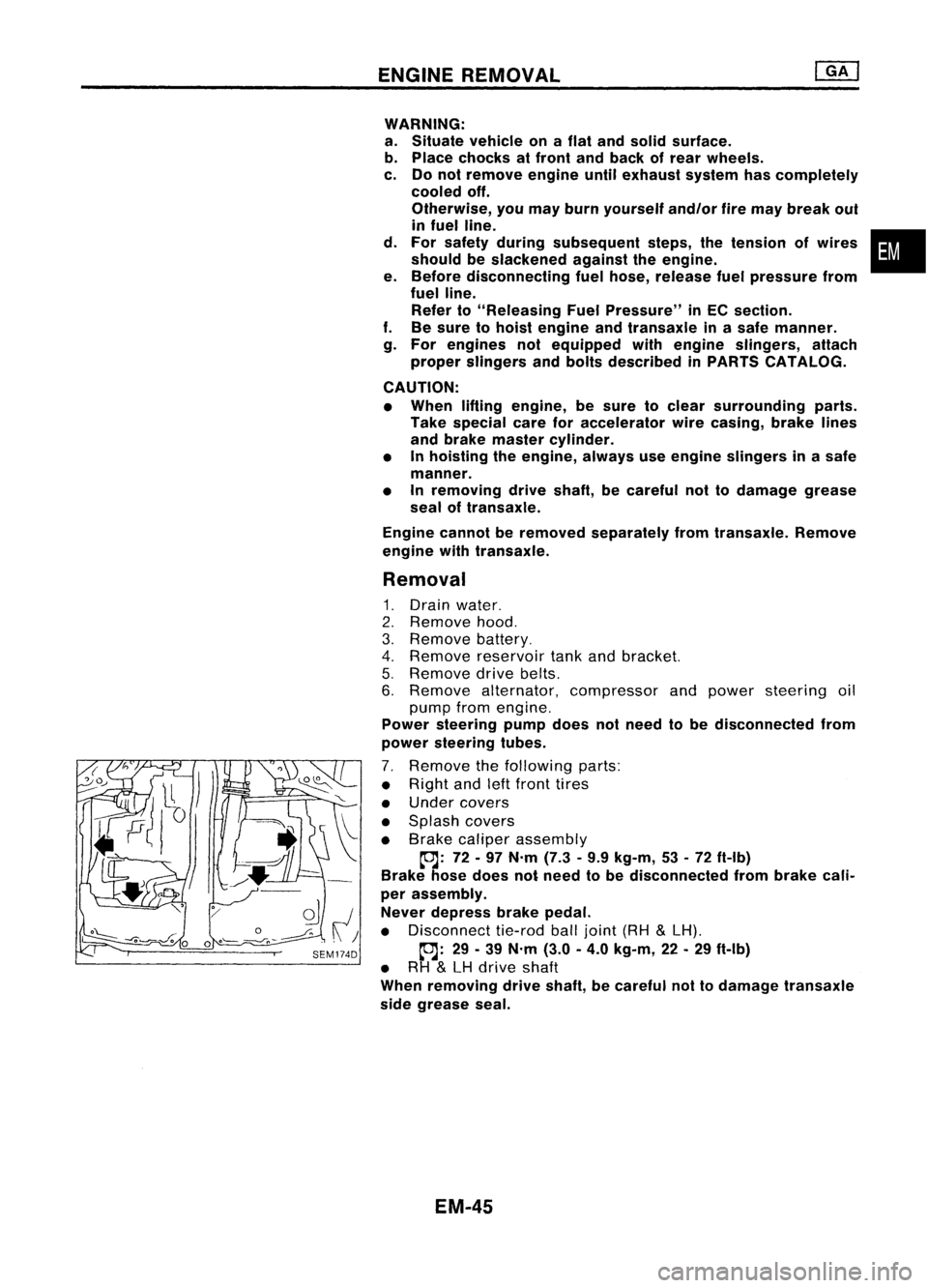
7. Remove thefollowing parts:
• Right andleftfront tires
• Under covers
• Splash covers
• Brake caliper assembly
~: 72-97 N'm (7.3•9.9 kg-m, 53•72 ft-Ib)
Brake hosedoes notneed tobe disconnected frombrake cali-
per assembly.
Never depress brakepedal.
• Disconnect tie-rodballjoint (RH
&
LH).
~: 29-39 N'm (3.0-4.0 kg-m, 22-29 ft-Ib)
• RH
&
LH drive shaft
When removing driveshaft, becareful nottodamage transaxle
side grease seal.
EM-45
•
Page 1278 of 1701
SEM092DENGINE
REMOVAL
WARNING:
• Situate vehicle onaflat and solid surface.
• Place chocks atfront andback ofrear wheels.
• Donot remove engineuntilexhaust systemhascompletely
cooled off.
Otherwise, youmay burn yourself and/orfiremay break out
in fuel line.
• For safety during subsequent steps,thetension ofwires
should beslackened againsttheengine.
• Before disconnecting fuelhose, release fuelpressure from
fuel line.
Refer to"Releasing FuelPressure" inEC section.
• Besure tohoist engine andtransaxle inasafe manner.
• For engines notequipped withengine slingers, attach
proper slingers andbolts described inPARTS CATALOG.
CAUTION:
• When liftingengine, becareful nottostrike adjacent parts,
especially thefollowing: Accelerator wirecasing, brake
lines, andbrake master cylinder.
• Inhoisting theengine, alwaysuseengine slingers inasafe
manner.
Removal
1. Remove engineundercoverandhood.
2. Drain coolant frombothcylinder block,andradiator.
3. Drain engine oilfrom drain plugofoil pan.
4. Remove vacuumhoses,fuelhoses, wires,harness andcon-
nectors andsoon.
5. Remove exhausttubes,balljoints anddrive shafts.
6. Remove radiatorandfans.
7. Remove drivebelts.
8. Remove alternator, compressor andpower steering oil
pump fromengine.
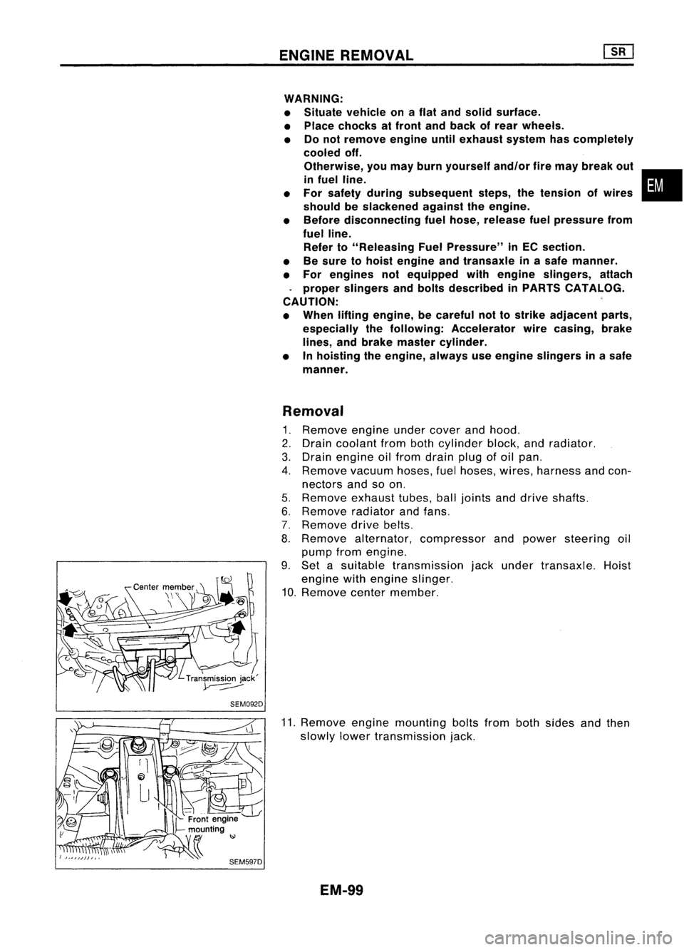
9. Set asuitable transmission jackunder transaxle. Hoist
engine withengine slinger.
10. Remove centermember.
11. Remove enginemounting boltsfrombothsides andthen
slowly lowertransmission jack.
EM-99
•
Page 1319 of 1701

~44 .54 (4.5 .5.5, 33.40) ~~
~ 44•54 (4.5 .5.5, 33•40)\"\ ~
-~1J.
~1
~~' ~64.74,
_' 2
(6.5.7.5, / \
~ 47.54),/'
rJ44. 54(4.5.5.5,3")
SEC.112 ENGINE
REMOVAL
~~ 44.54(4.5.5.5,33 -40)
~44 .54 (4.5 .5.5, 33.40) ~~
~ 44•54 (4.5 .5.5, 33•40)"\ ~
-~1J.
~1
~~' ~64.74,
_' 2
(6.5.7.5, / \
~ 47.54),/'
rJ44. 54(4.5.5.5,33 -40) ~\
'" ~~~44.54 \....
.- ,9
(4.5.5.5,
ttJJ 44-54 (4.5 •5.5, 33-40)
7
ttJJ64.75 ------~
@--."
('.5•7.5, 4~' \
y~
~~.~~ ~~f;fi\
~~~'~i':-l~"
k(j' --.
II!~o' ~
/'Oolk..,
ttJJ64.75 (6.5•7.5, 47•54) ~
~'o
@\
8,.'~
~- I
2
rJ64. 75(6.5 .7.5,47.54)..1"""-../
~2ft -."~
°
>
~44. 54
~@
ttJJ44.54(4.5 -5.5, 33. 40)
j~~~1 ~-/.~/
(4.5 -5.5, 33•40)
ti ~~
44•54
~'@
A
5~'
!-'~
~35'-4~.)5'~ ~/
,0
7
~ I~. '
.Vi
rJ44.54(4.5.5.5,33.40)
~ ~l
ttJJ44•54 (4.5 •5.5, 33•40)
~ 'l
o.o~
I...",;S'"
1.
..J'-;:7o
6
ttJJ44.54 (4.5 •5.5, 33•40)
~l \
'LrJ 44•54 (4.5 -5.5, 33•40)
ttJJ 44.54 (4.5 .5_5, 33.40)
rJ
N.m(kg-m. ft-Ibl
G)
Engine frontmounting
@
Engine mounting bracket
@
Gusset
@
Buffer rodbracket
@
Buffer rod
@
Center member
(J)
Transaxle mounting
@
Transaxle mountingbracket
SEM050F
@
Rolldamper
@)
Engine rearmounting
@
Engine rearmounting bracket
@
Dynamic damper
WARNING:
• Situate vehicle onaflat and solid surface.
• Place chocks atfront andback ofrear wheels.
• Donot remove engineuntilexhaust systemhascompletely
cooled off.Otherwise, youmay burn yourself and/orfire
may break outin.the fuel line.
• For safety during subsequent steps,thetension ofwires
should beslackened againsttheengine.
• Before removing frontaxlefrom transaxle, placesafety
stands underdesignated frontsupporting points.RefertoGI
section forlifting points andtowing.
• Besure tohoist engine andtransaxle inasafe manner.
• For engines notequipped withengine slingers, attach
proper slingers andbolts described inPARTS CATALOG.
CAUTION:
• When liftingengine, besure toclear surrounding parts.
Take special careforaccelerator wirecasing, brakelines
and brake master cylinder.
• Inhoisting theengine, alwaysuseengine slingers inasafe
manner.
• Inremoving driveshaft, becareful nottodamage transaxle
oil seal.
EM-140
Page 1356 of 1701
PRECAUTIONS
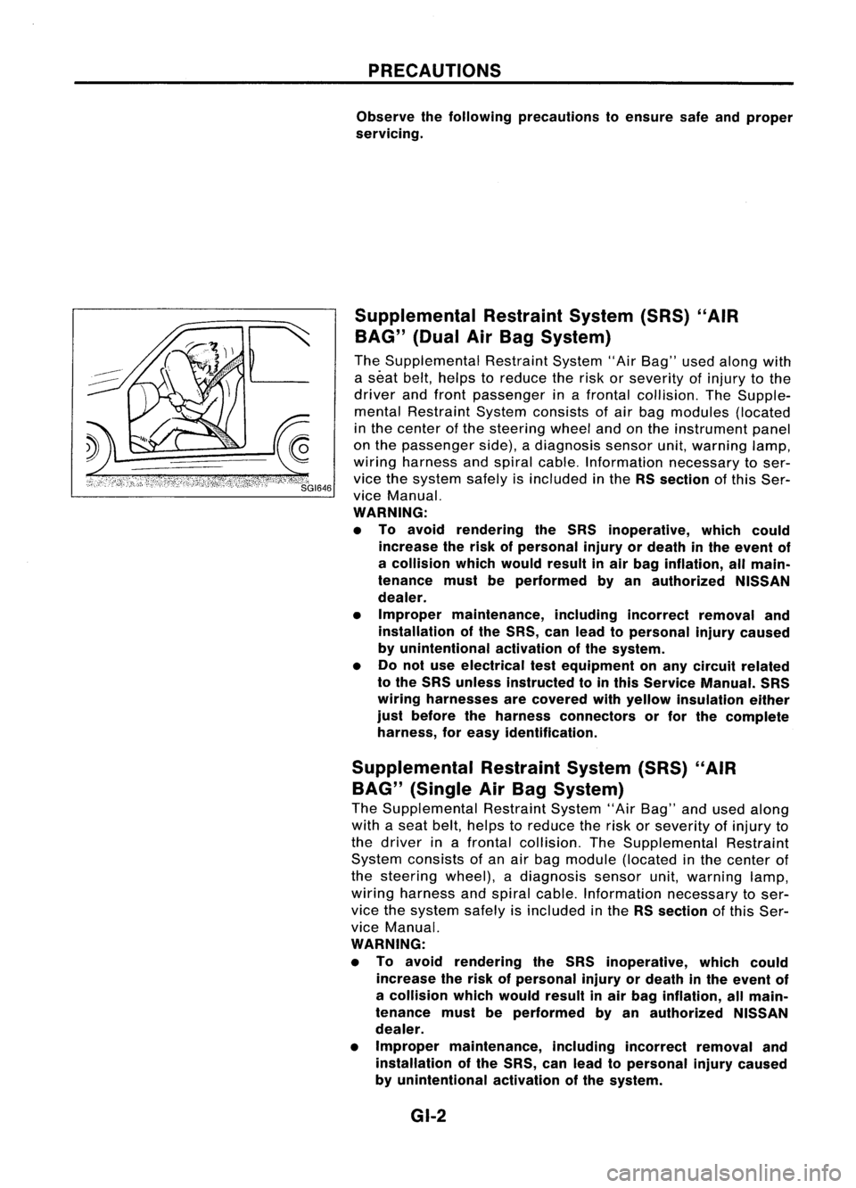
Observe thefollowing precautions toensure safeandproper
servicing.
Supplemental RestraintSystem(SRS)"AIR
BAG" (DualAirBag System)
The Supplemental RestraintSystem"AirBag" usedalong with
a seat belt,helps toreduce therisk orseverity ofinjury tothe
driver andfront passenger inafrontal collision. TheSupple-
mental Restraint Systemconsists ofair bag modules (located
in the center ofthe steering wheelandonthe instrument panel
on the passenger side),adiagnosis sensorunit,warning lamp,
wiring harness andspiral cable. Information necessarytoser-
vice thesystem safelyisincluded inthe RSsection ofthis Ser-
vice Manual.
WARNING:
• To avoid rendering theSRS inoperative, whichcould
increase therisk ofpersonal injuryordeath inthe event of
a collision whichwould resultinair bag inflation, allmain-
tenance mustbeperformed byan authorized NISSAN
dealer.
• Improper maintenance, includingincorrectremovaland
installation ofthe SRS, canlead topersonal injurycaused
by unintentional activationofthe system.
• Donot use electrical testequipment onany circuit related
to the SRS unless instructed tointhis Service Manual. SRS
wiring harnesses arecovered withyellow insulation either
just before theharness connectors orfor the complete
harness, foreasy identification.
Supplemental RestraintSystem(SRS)"AIR
BAG" (Single AirBag System)
The Supplemental RestraintSystem"AirBag" andused along
with aseat belt, helps toreduce therisk orseverity ofinjury to
the driver inafrontal collision. TheSupplemental Restraint
System consists ofan air bag module (located inthe center of
the steering wheel),adiagnosis sensorunit,warning lamp,
wiring harness andspiral cable. Information necessarytoser-
vice thesystem safelyisincluded inthe RSsection ofthis Ser-
vice Manual.
WARNING:
• To avoid rendering theSRS inoperative, whichcould
increase therisk ofpersonal injuryordeath inthe event of
a collision whichwould resultinair bag inflation, allmain-
tenance mustbeperformed byan authorized NISSAN
dealer.
• Improper maintenance, includingincorrectremovaland
installation ofthe SRS, canlead topersonal injurycaused
by unintentional activationofthe system.
GI-2
(Cont'd)
4. Caulk tankinspecified sequence withTool.
•
Keep toolperpendicular to
the radiator.")