Page 765 of 1701
ON-BOARDDIAGNOSTIC SYSTEMDESCRIPTION @KJ
Malfunction Indicatorlamp(Mil)(Cont'd)
DIAGNOSTIC TESTMODE I-BULB CHECK
In this mode, theMALFUNCTION INDICATORLAMPonthe instrument panelshould stayON.Ifitremains
OFF, check thebulb. Refer toEL section ("WARNING LAMPSANDCHIME") orsee EC-223.
DIAGNOSTIC TESTMODE I-MALFUNCTION WARNING
MALFUNCTION INDICATORLAMP
ON
OFF Condition
Engine coolant temperature sensorcircuitmalfunction oroverheating isdetected, or
the ECM's CPUismalfunctioning.
No malfunction.
• These Diagnostic TroubleCodeNumbers areclarified inDiagnostic TestMode II(SELF-DIAGNOS-
TIC RESULTS).
DIAGNOSTIC TESTMODE II-SELF-DIAGNOSTIC RESULTS
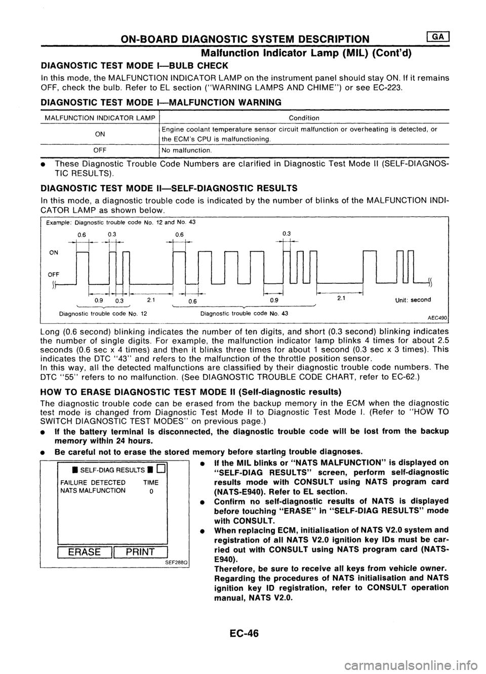
In this mode, adiagnostic troublecodeisindicated bythe number ofblinks ofthe MALFUNCTION INDI-
CATOR LAMPasshown below.
Example: Diagnostic troublecodeNo.12and No.43
ON
0.6
03
111-'1
0.6
II
0.3
OFF
j
~
~~ -I.
--.1
-4--1--
Q9 O~ 21 OB Q9
'--------v----' '--------v------~
Diagnostic troublecodeNo.12 DiagnostictroublecodeNo.43
2.1
Unit:second
AEC490
• SELF-DIAG RESULTS.
0
FAILURE DETECTED TIME
NATS MALFUNCTION
0
I
ERASE
II
PRINT
I
SEF288Q
Long
(0.6second) blinkingindicates thenumber often digits, andshort (0.3second) blinkingindicates
the number ofsingle digits. Forexample, themalfunction indicatorlampblinks 4times forabout 2.5
seconds (0.6secx4 times) andthen itblinks threetimes forabout 1second (0.3secx3 times). This
indicates theDTC "43" andrefers tothe malfunction ofthe throttle position sensor.
In this way, allthe detected malfunctions areclassified bytheir diagnostic troublecodenumbers. The
DTC "55" refers tono malfunction. (SeeDIAGNOSTIC TROUBLECODECHART, refertoEC-62.)
HOW TOERASE DIAGNOSTIC TESTMODE II(Self-diagnostic results)
The diagnostic troublecodecanbeerased fromthebackup memory inthe ECM when thediagnostic
test mode ischanged fromDiagnostic TestMode IIto Diagnostic TestMode
I.
(Refer to"HOW TO
SWITCH DIAGNOSTIC TESTMODES" onprevious page.)
• Ifthe battery terminal isdisconnected, thediagnostic troublecodewillbelost from thebackup
memory within24hours.
• Becareful nottoerase thestored memory before
startin~
troublediagnoses.
• If
the MIL blinks or"NATS MALFUNCTION" isdisplayed on
"SELF-OIAG RESULTS"screen,perform self-diagnostic
results modewithCONSULT usingNATS program card
(NATS-E940). RefertoEL section.
• Confirm noself-diagnostic resultsofNATS isdisplayed
before touching "ERASE" in"SELF-DIAG RESULTS"mode
with CONSULT.
• When replacing ECM,initialisation ofNATS V2.0system and
registration ofall NATS V2.0ignition key10smust becar-
ried outwith CONSULT usingNATS program card(NATS-
E940).
Therefore, besure toreceive allkeys from vehicle owner.
Regarding theprocedures ofNATS initialisation andNATS
ignition key10registration, refertoCONSULT operation
manual, NATS V2.0.
EC-46
Page 969 of 1701
ON-BOARDDIAGNOSTIC SYSTEMDESCRIPTION
\ I/
'~/'
- CHECK-
/
.......
/ I\
SEF051P
Malfunction
Indicatorlamp(Mil)
1. The malfunction indicatorlampwilllight upwhen theigni-
tion switch isturned ONwithout theengine running. Thisis
a bulb check.
• Ifthe malfunction indicatorlampdoes notlight up,refer to
EL section ("WARNING LAMPSANDCHIME") orsee
EC-370.
2. When theengine isstarted, themalfunction indicatorlamp
should gooff.
Condition Diagnostic
Diagnostic
Test Mode I TestMode II
Engine
stopped BULBCHECK SELF-DIAGNOSTIC
Ignition
0
RESULTS
switch in
"ON" posi-
tion Engine
HEATEDOXYGEN
~ running
MALFUNCTION
SENSORMONI-
ID
WARNING
TOR
EC-250
Page 970 of 1701
ON-BOARDDIAGNOSTIC SYSTEMDESCRIPTION
Malfunction IndicatorLamp(MIL)(Cont'd)
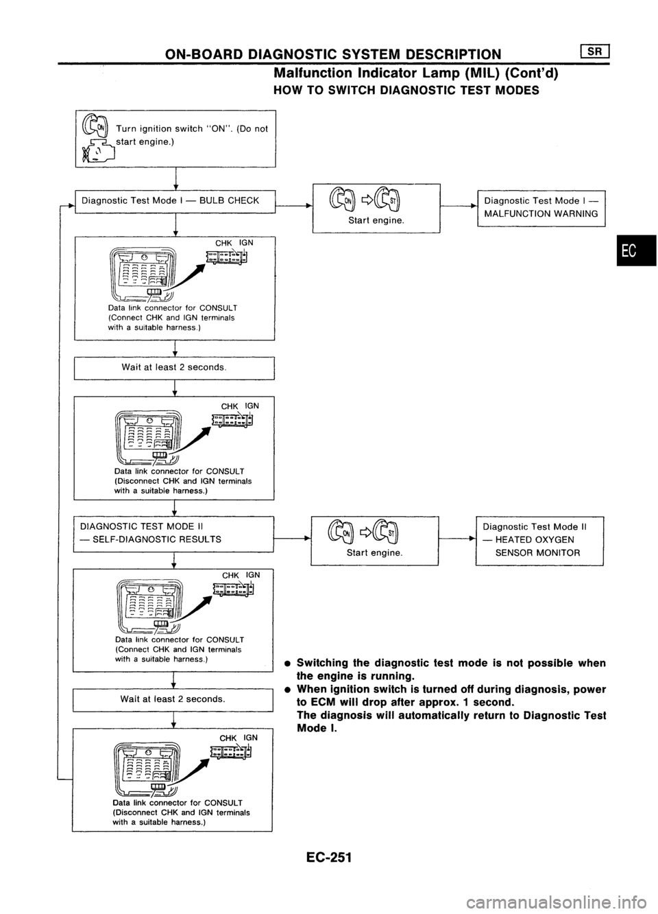
HOW TOSWITCH DIAGNOSTIC TESTMODES
~ Turnignition switch"ON".(Donot
~ startengine.)
~
•SWitching thediagnostic testmode isnot possible when
the engine isrunning.
• When ignition switchisturned offduring diagnosis, power
to ECM willdrop afterapprox. 1second.
The diagnosis willautomatically returntoDiagnostic Test
Mode
I.
Diagnostic
TestMode I- BULB CHECK
1
~yW~r
~-~
Data linkconnector forCONSULT
(Connect CHKandIGNterminals
with asuitable harness.)
Wait atleast 2seconds.
CHKIGN
~J/~l
~-~
Data linkconnector forCONSULT
(Disconnect CHKandIGNterminals
with asuitable harness.)
DIAGNOSTIC TESTMODE II
- SELF-DIAGNOSTIC RESULTS
~
f!i~:~~-~
w;ir
l~mv
-~
Data linkconnector forCONSULT
(Connect CHKandIGN terminals
with asuitable harness.)
Wait atleast 2seconds.
~
~/~~N
~-~
Data linkconnector forCONSULT
(Disconnect CHKandIGNterminals
with asuitable harness.)
I
Startengine.
Start engine. Diagnostic
TestMode I-
MALFUNCTION WARNING
Diagnostic TestMode II
- HEATED OXYGEN
SENSOR MONITOR
•
EC-251
Page 971 of 1701
ON-BOARDDIAGNOSTIC SYSTEMDESCRIPTION ~
Malfunction IndicatorLamp(MIL)(Cont'd)
DIAGNOSTIC TESTMODE I-BULB CHECK
In this mode, theMALFUNCTION INDICATORLAMPonthe instrument panelshould stayON.If
it
remains
OFF, check thebulb. Refer toEL section ("WARNING LAMPSANDCHIME") orsee EC-370.
DIAGNOSTIC TESTMODE I-MALFUNCTION WARNING
MALFUNCTION INDICATORLAMP
ON
OFF Condition
Engine coolant temperature sensorcircuitmalfunction isdetected, orthe ECM's CPU
is malfunctioning.
No malfunction.
• These Diagnostic TroubleCodeNumbers areclarified inDiagnostic TestMode II(SELF-DIAGNOS-
TIC RESULTS).
DIAGNOSTIC TESTMODE II-SELF-DIAGNOSTIC RESULTS
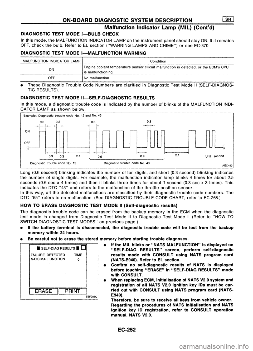
In this mode, adiagnostic troublecodeisindicated bythe number ofblinks ofthe MALFUNCTION INDI-
CATOR LAMPasshown below.
Example: Diagnostic troublecodeNo.12and No.43
0.6 0.3
ON
1111
OFF ~
0.9 0.3
0.6
--I~
2.1 0.6
0.9
0.3
Unit:second
Diagnostic troublecodeNo.12 Diagnostic
troublecodeNo.43
AEC490
• SELF-DIAG RESULTS.
0
FAILURE DETECTED TIME
NATS MALFUNCTION
0
I
ERASE
II
PRINT
I
SEF288Q
Long
(0.6second) blinkingindicates thenumber often digits, andshort (0.3second) blinkingindicates
the number ofsingle digits.Forexample, themalfunction indicatorlampblinks 4times forabout 2.5
seconds (0.6secx4times) andthen itblinks threetimes forabout 1second (0.3sec x3 times). This
indicates theDTC "43" andrefers tothe malfunction ofthe throttle position sensor.
In this way, allthe detected malfunctions areclassified bytheir diagnostic troublecodenumbers. The
DTC "55" refers tono malfunction. (SeeDIAGNOSTIC TROUBLECODECHART, refertoEC-268.)
HOW TOERASE DIAGNOSTIC TESTMODE II(Self-diagnostic results)
The diagnostic troublecodecanbeerased fromthebackup memory inthe ECM when thediagnostic
test mode ischanged fromDiagnostic TestMode IIto Diagnostic TestMode
I.
(Refer to"HOW TO
SWITCH DIAGNOSTIC TESTMODES" onprevious page.)
• Ifthe battery terminal isdisconnected, thediagnostic troublecodewillbelost from thebackup
memory within24hours.
• Becareful nottoerase thestored memory beforestarting- troublediagnoses.
• Ifthe MIL blinks or"NATS MALFUNCTION" isdisplayed on
"SELF-OIAG RESULTS"screen,perform self-diagnostic
results modewithCONSULT usingNATS program card
(NA TS-E940). RefertoEL section.
• Confirm noself-diagnostic resultsofNATS isdisplayed
before touching "ERASE" in"SELF-DiAG RESULTS"mode
with CONSULT.
• When replacing ECM,inltialisation ofNATS V2.0system and
registration ofall NATS V2.0 Ignition keyIDsmust becar-
ried outwith CONSULT usingNATS program card(NATS-
E940).
Therefore, besure toreceive allkeys from vehicle owner.
Regarding theprocedures ofNATS initialisation andNATS
ignition key
10
registration, refertoCONSULT operation
manual, NATS V2.0.
EC-252
Page 1098 of 1701
EF791AINJECTION
NOZZLE
Test andAdjustment
WARNING:
When usingnozzle tester,becareful nottoallow diesel fuel
sprayed fromnozzle tocontact yourhands orbody, andmake
sure your eyes areproperly protected withgoggles .
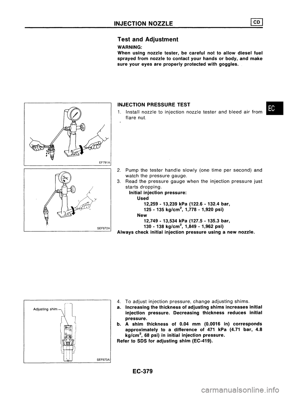
INJECTION PRESSURE TEST
1. Install nozzle toinjection nozzletesterandbleed airfrom
flare nut.
•
SEF672A
2.
Pump thetester handle slowly(onetime persecond) and
watch thepressure gauge.
3. Read thepressure gaugewhentheinjection pressure just
starts dropping.
Initial injection pressure:
Used 12,259 -13,239 kPa(122.6 -132.4 bar,
125 -135 kg/cm
2,
1,778•1,920 psi)
New 12,749 -13,534 kPa(127.5 -135.3 bar,
130 -138 kg/cm
2,
1,849•1,962 psi)
Always checkinitialinjection pressure usinganew nozzle.
Adjusting shim
SEF673A
4.
Toadjust injection pressure, changeadjusting shims.
a. Increasing thethickness ofadjusting shimsincreases initial
injection pressure. Decreasing thicknessreducesinitial
pressure.
b. Ashim thickness of0.04 mm(0.0016 in)corresponds
approximately toadifference of471 kPa (4.71 bar,4.8
kg/cm
2,
68psi) ininitial injection pressure.
Refer toSDS foradjusting shim(EC-419).
EC-379
Page 1144 of 1701
ENGINELUBRICATION SYSTEM
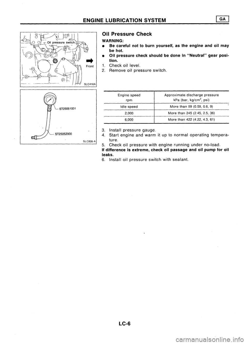
3. Install pressure gauge.
4. Start engine andwarm itup tonormal operating tempera-
ture.
5. Check oilpressure withengine running underno-load.
If difference isextreme, checkoilpassage andoilpump foroil
leaks.
6. Install oilpressure switchwithsealant.
Oil
Pressure Check
WARNING: • Becareful nottoburn yourself, asthe engine andoilmay
be hot.
• Oilpressure checkshould bedone in"Neutral" gearposi-
tion.
1. Check oillevel.
2. Remove oilpressure switch.
ST25051001 SLC926-A
Engine
speed
rpm
Idle speed
2,000
6,000 Approximate
dischargepressure
kPa (bar,
kg/cm
2,
psi)
More than59(0.59, 0.6,9)
More than245(2.45, 2.5,36)
More than422(4.22, 4.3,61)
LC-6
Page 1150 of 1701
ENGINECOOLING SYSTEM
System Check
WARNING: Never remove theradiator capwhen theengine ishot; serious
burns couldbecaused byhigh pressure fluidescaping fromthe
radiator.
Wrap athick cloth around capandcarefUlly loosenita quarter
turn torelease built-uppressure. Thenremove thecap com-
pletely.
CHECKING COOLINGSYSTEMHOSES
Check hosesforimproper attachment, leaks,cracks, damage,
loose connections, chafinganddeterioration.
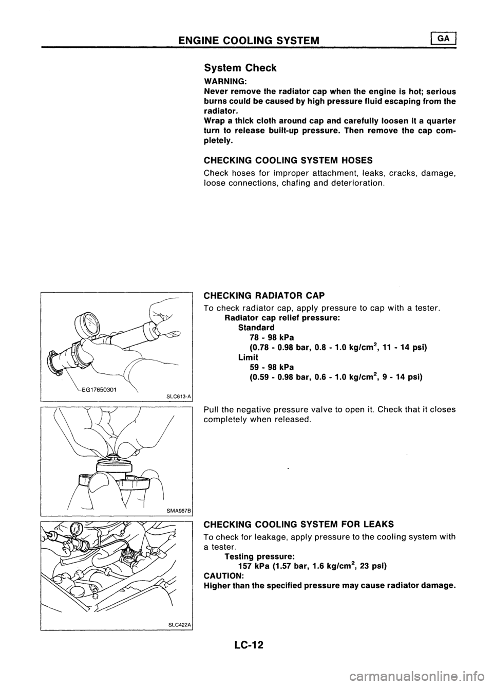
CHECKING RADIATORCAP
To check radiator cap,apply pressure tocap with atester.
Radiator caprelief pressure:
Standard
78 -98 kPa
(0.78 -0.98 bar,0.8-1.0 kg/cm
2,
11-14 psi)
Limit
59 -98 kPa
(0.59 -0.98 bar,0.6-1.0 kg/cm
2,
9-14 psi)
SLC613-A
Pullthenegative pressure valvetoopen it.Check thatitcloses
completely whenreleased.
CHECKING COOLINGSYSTEMFORLEAKS
To check forleakage, applypressure tothe cooling systemwith
a tester.
Testing pressure:
157 kPa (1.57 bar,1.6kg/cm
2,
23psi)
CAUTION: Higher thanthespecified pressure maycause radiator damage.
SLC422A LC-12
Page 1155 of 1701
ENGINELUBRICATION SYSTEM
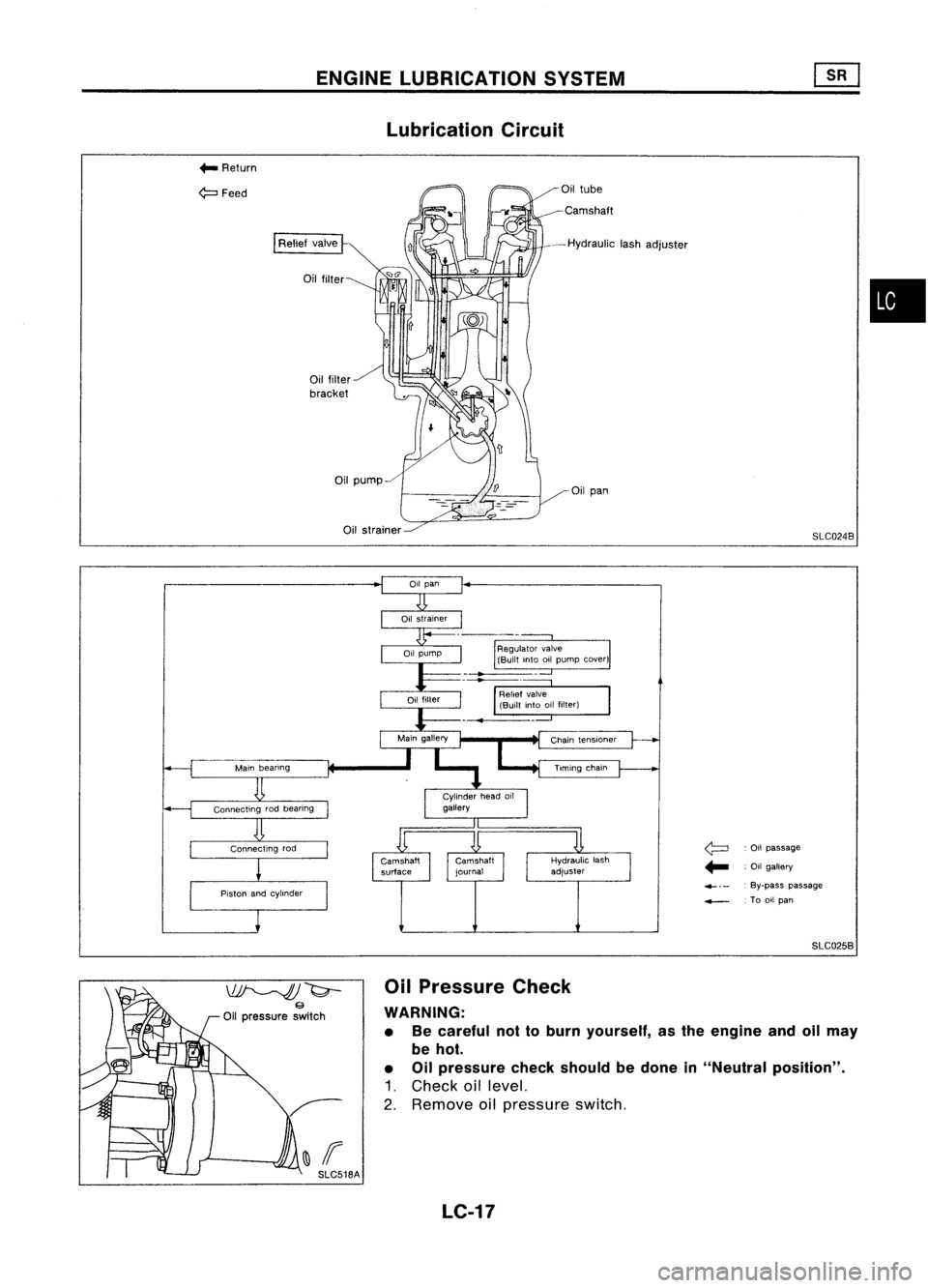
Lubrication Circuit
... Return
~Feed Oil
tube
Camshaft
--Hydraulic lashadjuster
Oil pan
SLC0248
•
Oil passage
.- :Oil gallery
4-. - .
By-pass passage
....--. Tooilpan
SLC0258
~~
9
Oil pressure switch
~If SLC518A Oil
Pressure Check
WARNING:
• Becareful nottoburn yourself, asthe engine andoilmay
be hot.
• Oilpressure checkshould bedone in"Neutral position".
1. Check oillevel.
2. Remove oilpressure switch.
LC-17

1. The malfunction indicatorlampwilllight upwhen theigni-
tion switch istur")