Page 1519 of 1701
ENGINEMAINTENANCE ~
Changing FuelFilter (Cont'd)
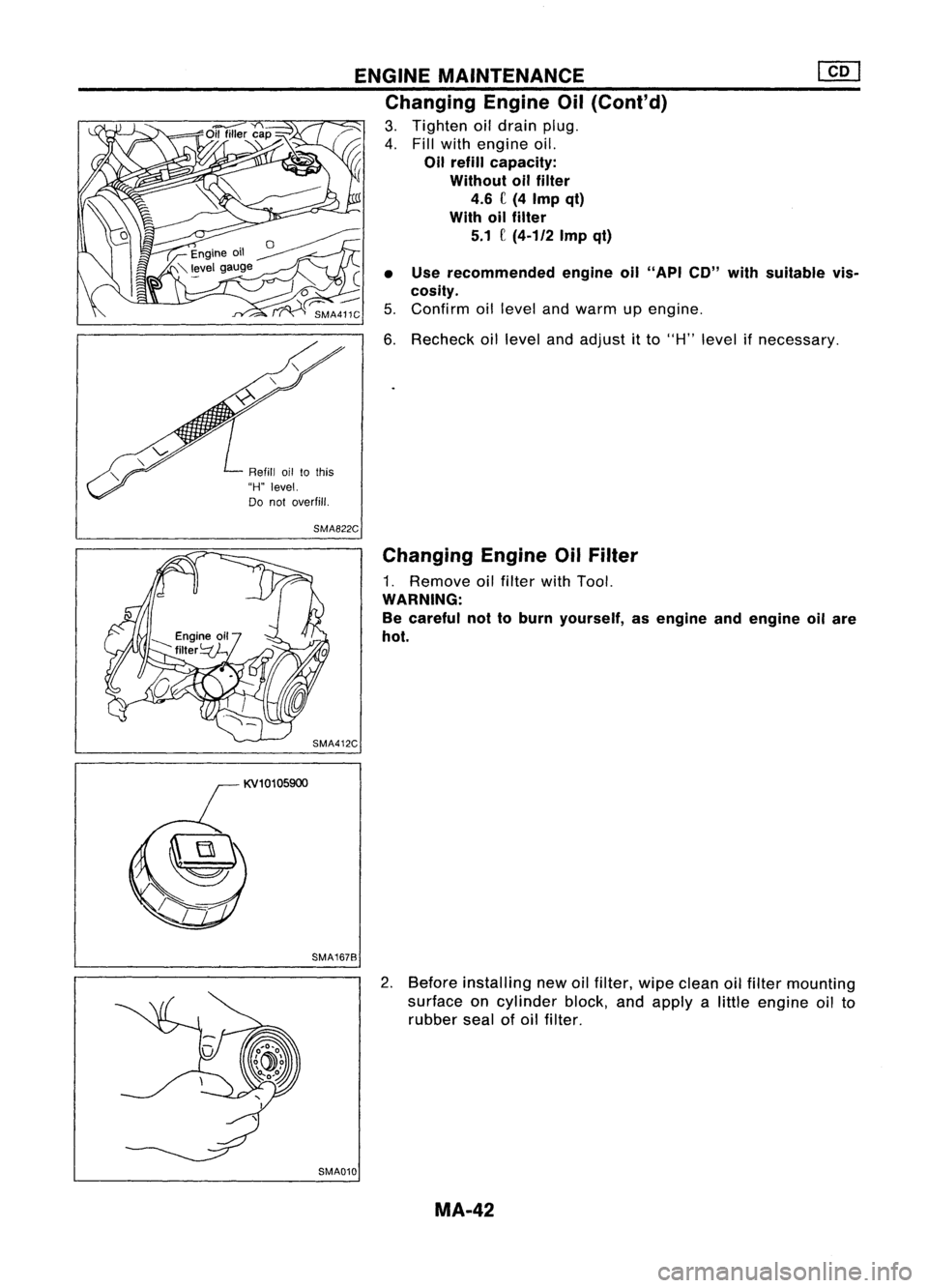
~ 1.Remove fuseforfuel pump.
~ 2.Start engine.
3. After engine stalls,crankengine twoorthree times
to make surethatfuel pressure isreleased. •
4. Turn ignition switchoffand install fuseforfuel pump.
i
Unit: C(Imp qt)
SMA790C
5.Loosen fuelhose clamps.
6. Replace fuelfilter.
• Becareful nottospill fuelover engine compartment. Place
a shop towel toabsorb fuel.
• Use ahigh-pressure typefuelfilter. Donot use asynthetic
resinous fuelfilter.
• When tightening fuelhose clamps, referto"Checking Fuel
Lines" .
Changing AirCleaner Filter
Viscous papertype
The viscous papertypefilter does notneed cleaning between
renewals.
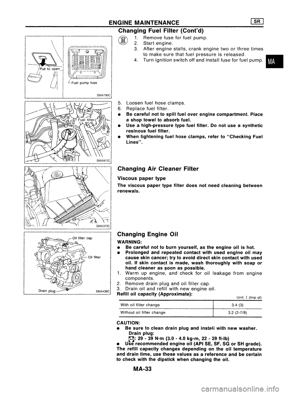
Changing EngineOil
WARNING:
• Becareful nottoburn yourself, asthe engine oilishot.
• Prolonged andrepeated contactwithused engine oilmay
cause skincancer; trytoavoid direct skincontact withused
oil. Ifskin contact ismade, washthoroughly withsoap or
hand cleaner as$oon aspossible.
1. Warm upengine, andcheck foroilleakage fromengine
components.
2. Remove drainplugandoilfiller cap.
3. Drain oiland refill withnewengine oil.
Refill oilcapacity (Approximate):
With oilfilter change
Without oilfilter change
3.4
(3)
3.2 (2-7/8)
CAUTION: • Besure toclean drainplugandinstClili withnewwasher.
Drain plug:
~: 29-39 N'm (3.0
0
4.0 kg-m, 22-29 ftolb)
• Use recommended engineoil(API SE,SF,SGorSH grade).
The refill capacity changes depending onthe oiltemperature
and drain time,usethese values asareference andbecertain
to check withthedipstick whenchanging theoil.
MA-33
Page 1520 of 1701
ENGINEMAINTENANCE [}[]
Changing EngineOil(Cont'd)
4. Check oillevel.
5. Start engine andcheck areaaround drainplugandoilfilter
for oilleakage.
6. Run engine forafew minutes, thenturnitoff. After several
minutes, checkoillevel.
Refill oil10this
"H" level.
Do not overfill.
SMA390C
Changing OilFilter
1. Remove oilfilter withTool.
WARNING:
Be careful nottoburn yourself, asthe engine andtheengine
oil are hot.
2. Clean oilfilter mounting surfaceoncylinder block.Coat
rubber sealofnew oilfilter withengine oil.
2/3
ofaturn
-------
OK SMA010
3.Screw inthe oilfilter untilaslight resistance isfelt, then
tighten anadditional 2/3turn.
4. Add engine oil.
Refer toChanging EngineOil.
• Clean excess oilfrom engine.
Changing SparkPlugs(Platinum-tipped type)
1. Disconnect ignitionwiresfromspark plugsatboot. Donot
pull onthe wire.
MA-34
Page 1524 of 1701
ENGINEMAINTENANCE
Air conditioner
compressor
SMA442C
AMA054 Manifold
NutCheck
1. Remove exhaustmanifold cover.
2. Tighten manifold boltsandnuts tothe specified torque.
Refer to"SERVICE DATAANDSPECIFICATIONS (SOS)".
3. Install exhaust manifold cover.
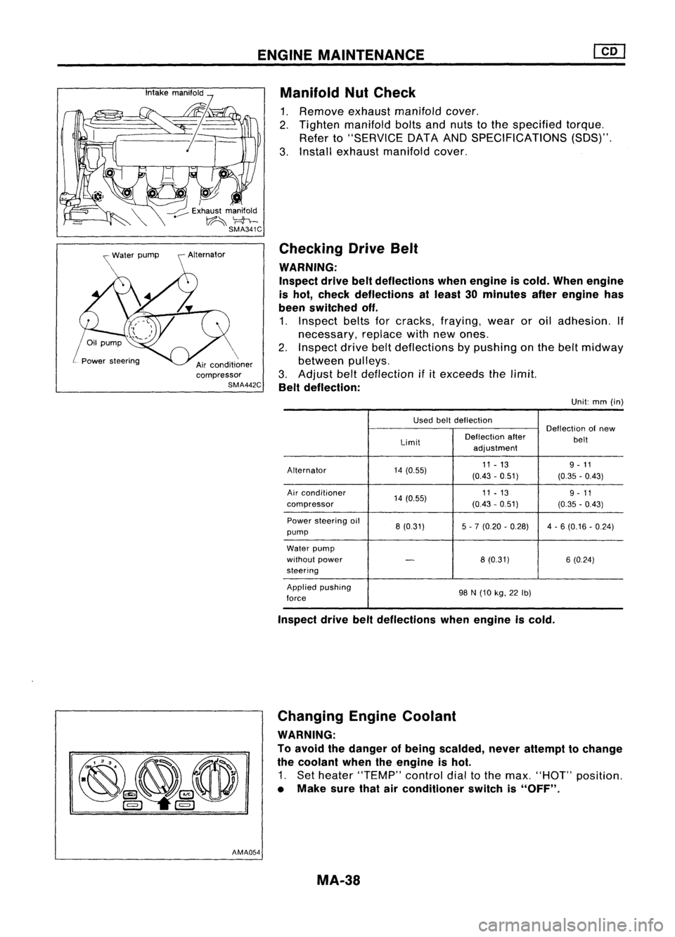
Checking DriveBelt
WARNING:
Inspect drivebeltdeflections whenengine iscold. When engine
is hot, check deflections atleast 30minutes afterengine has
been switched off.
1. Inspect beltsforcracks, fraying, wearoroil adhesion. If
necessary, replacewithnewones.
2. Inspect drivebeltdeflections bypushing onthe belt midway
between pulleys.
3. Adjust belt
deflection
if
it
exceeds thelimit.
Belt deflection:
Unit:mm(in)
Used beltdeflection
Deflectionofnew
Limit Deflection
after
belt
adjustment
Alternator 14(0.55) 11
-13 9-11
(0.43 -051) (0.35-0.43)
Air conditioner
14(0.55) 11
-13
9-11
compressor (0.43-051) (0.35-0.43)
Power steering oil
8(0.31) 5-7 (0.20 -0.28) 4-6 (0.16 -0.24)
pump
Water pump
without power
-
8(0.31) 6(0.24)
steering
Applied pushing
98N(10 kg,22Ib)
force
Inspect drivebeltdeflections whenengine iscold.
Changing EngineCoolant
WARNING:
To avoid thedanger ofbeing scalded, neverattempt tochange
the coolant whentheengine ishot.
1. Set heater "TEMP" controldialtothe max. "HOT" position.
• Make surethatairconditioner switchis"OFF".
MA-38
Page 1527 of 1701
ENGINEMAINTENANCE
Changing AirCleaner Filter
The viscous papertypeaircleaner filterdoes notrequire any
cleaning operation betweenrenewals.
Water Draining, FuelFilter Check and
Replacement
DRAINING WATER
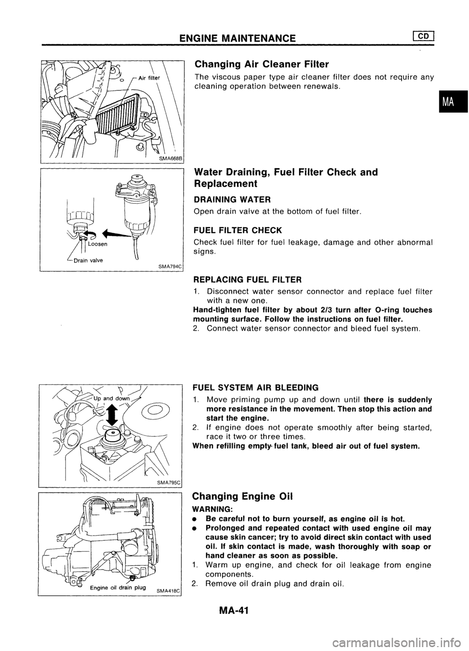
Open drainvalve atthe bottom offuel filter.
FUEL FILTER CHECK
Check fuelfilter forfuel leakage, damageandother abnormal
signs.
•
SMA794C REPLACING FUELFILTER
1. Disconnect watersensor connector andreplace fuelfilter
with anew one.
Hand-tighten fuelfilter byabout 2/3turn after O-ring touches
mounting surface.Followtheinstructions onfuel filter.
2. Connect watersensor connector andbleed fuelsystem.
FUEL SYSTEM AIRBLEEDING
1. Move priming pumpupand down until
there issuddenly
more resistance inthe movement. Thenstopthisaction and
start theengine.
2. Ifengine doesnotoperate smoothly afterbeing started,
race ittwo orthree times.
When refilling empty-fueltank, bleed airout offuel system.
Changing EngineOil
WARNING:
• Becareful nottoburn yourself, asengine oilishot.
• Prolonged andrepeated contactwithused engine oilmay
cause skincancer; trytoavoid direct skincontact withused
oil. Ifskin contact ismade, washthoroughly withsoap or
hand cleaner assoon aspossible.
1. Warm upengine, andcheck foroilleakage fromengine
components.
2. Remove oildrain pluganddrain oil.
MA-41
Page 1528 of 1701
ENGINEMAINTENANCE
Changing EngineOil(Cont'd)
3. Tighten oildrain plug.
4. Fillwith engine oil.
Oil refill capacity:
Without oilfilter
4.6 C(4 Imp qt)
With oilfilter
5.1 C
(4-1/2
Impqt)
• Use recommended engineoil"API CD"with suitable vis-
cosity.
5. Confirm oillevel andwarm upengine.
6. Recheck oillevel andadjust itto "H" level ifnecessary.
Refill oiltothis
"H" level.
Do not overfill.
SMA822C
Changing EngineOilFilter
1. Remove oilfilter withTool.
WARNING:
Be careful nottoburn yourself, asengine andengine oilare
hot.
SMA412C
SMA167B
2.Before installing newoilfilter, wipeclean oilfilter mounting
surface oncylinder block,andapply alittle engine oilto
rubber sealofoil filter.
SMA010 MA-42
Page 1529 of 1701
![NISSAN ALMERA N15 1995 Service Manual
2/3
ofaturn
ENGINE
MAINTENANCE @Q]
Changing EngineOilFilter (Cont'd)
3. Screw oilfilter onuntil aslight resistance isfelt, then tighten
an additional 2/3turn.
4. Warm upengine andcheck oillevel](/manual-img/5/57349/w960_57349-1528.png "NISSAN ALMERA N15 1995 Service Manual
2/3
ofaturn
ENGINE
MAINTENANCE @Q]
Changing EngineOilFilter (Cont'd)
3. Screw oilfilter onuntil aslight resistance isfelt, then tighten
an additional 2/3turn.
4. Warm upengine andcheck oillevel")
2/3
ofaturn
ENGINE
MAINTENANCE @Q]
Changing EngineOilFilter (Cont'd)
3. Screw oilfilter onuntil aslight resistance isfelt, then tighten
an additional 2/3turn.
4. Warm upengine andcheck oillevel.
5. Adjust oillevel ifnecessary. •
Refer toStep 4in "Changing EngineOil",MA-42.
i
• Clean excess oilfrom engine.
SMA229B Checking InjectionNozzle
1. Remove injection deliverytubesandfuel spill tube.
2. Remove nozzlewithasuitable tool[span 27mm (1.06 in)].
WARNING:
When usingnozzle tester,becareful nottoallow diesel fuel
sprayed fromnozzle tocome intocontact withyour hand or
body, andmake surethatyour eyes areproperly protected.
3. Clean andcheck nozzles.
4. Install nozzle toinjection nozzletesterandbleed airfrom
flare nut.
5. Check initialinjection pressure bypumping testerhandle
one time persecond.
EF791A
6.Install injector topressure tester.
7. Check initialinjection pressure bypumping testerhandle
slowly (onetime persecond).
Injection pressure:
12,749 kPa(127.5 bar,130kg/cm
2,
1,849psi)
• Always checkinitialinjection pressure beforeinstalling new
nozzle.
Good
\
I
,
,
I
Wrong SEF672A
8.Check fuelspray pattern bypumping testerhandle quickly
(4 or 6times persecond).
9. Ifinitial injection pressure orinjection nozzleisnot normal,
adjust orclean injection nozzleorreplace it.
Refer toEC section forinjection pressure adjustment.
10. Install allinjection nozzlesandsecurely connectfuelspill
tube anddelivery tubes.
11. Bleed airfrom fuelsystem andcheck forfuel leakage with
engine running.
EF794A
MA.43
Page 1613 of 1701
ON-VEHICLESERVICE
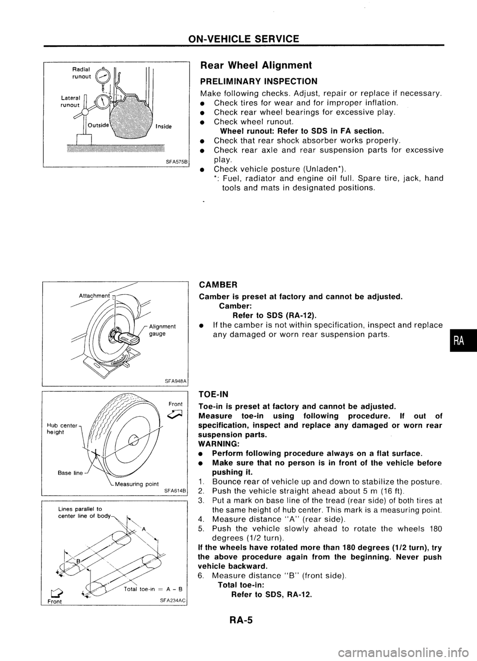
Rear Wheel Alignment
PRELIMINARY INSPECTION
Make following checks.Adjust,repairorreplace ifnecessary.
• Check tiresforwear andforimproper inflation.
• Check rearwheel bearings forexcessive play.
• Check wheelrunout.
Wheel runout: RefertoSOS inFA section.
• Check thatrear shock absorber worksproperly.
• Check rearaxleandrear suspension partsforexcessive
SFA575B
play.
• Check vehicle posture (Unladen*).
*: Fuel, radiator andengine oilfull. Spare tire,jack, hand
tools andmats indesignated positions.
•
CAMBER
Camber ispreset atfactory andcannot beadjusted.
Camber: Refer toSOS (RA-12).
• Ifthe camber isnot within specification, inspectandreplace
any damaged orworn rearsuspension parts.
TOE-IN
Toe-in ispreset atfactory andcannot beadjusted.
Measure toe-inusingfollowing procedure. Ifout of
specification, inspectandreplace anydamaged orworn rear
suspension parts.
WARNING:
• Perform following procedure alwaysonaflat surface.
• Make surethatnoperson isin front ofthe vehicle before
pushing it.
1. Bounce rearofvehicle upand down tostabilize theposture.
2. Push thevehicle straight aheadabout5m (16
ft).
3. Putamark onbase lineofthe tread (rearside) ofboth tires at
the same height ofhub center. Thismark isameasuring point.
4. Measure distance"A"(rear side).
5. Push thevehicle slowlyaheadtorotate thewheels 180
degrees (1/2turn).
If the wheels haverotated morethan180degrees (1/2turn), try
the above procedure againfromthebeginning. Neverpush
vehicle backward.
6. Measure distance"B"(front side).
Total toe-in:
Refer toSOS, RA-12.
Front
SFA948A
SFA614B
SFA234AC
Lines
parallel to
center lineofbOdY~
Q
Front
Hub
center
height
RA-5
Page 1621 of 1701
RESTRAINTSYSTEM
SECTION
RS
CONTENTS
PRECAUTION 2
Supplemental RestraintSystem(SRS)"AIR
BAG" (DualAirBag System) 2
Supplemental RestraintSystem(SRS)"AIR
BAG" (Single AirBag System) 2
SEAT BELTS
3
Front SeatBelt 3
Rear SeatBel!. 5
SUPPLEMENTAL RESTRAINTSYSTEM(SRS) 8
Precautions forSRS "AirBag" and"Seat Belt
Pre-tensioner" Service 8
Special Service Tools 8
Description 9
SRS Component PartsLocation 10
Maintenance Items 11
Removal andInstallation -Diagnosis Sensor
Unit. 12
Removal andInstallation -Seat BeltPre-
tensioner (Mechanical Type) 13
Removal andInstallation -Air Bag Module
and Spiral Cable(DualAirBag System) 14
Removal andInstallation -Air Bag Module
and Spiral Cable(Single AirBag System) 14
Removal -Air Bag Module andSpiral Cable 15
Removal -Front Passenger AirBag Module
(Dual AirBag System) 16Installation
-Air Bag Module andSpiral
Cable 17
Installation -Front Passenger AirBag
Module (DualAirBag System) 18
Disposal ofAir Bag Module andSeat Belt
Pre-tensioner 19
TROUBLE DIAGNOSES -Supplemental
Restraint System(SRS) 25
How toPerform TroubleDiagnoses forQuick
and Accurate Repair 25
TROUBLE DIAGNOSES -Supplemental
Restraint System(SRS)-Dual AirBag System 28
Schematic 28
Wiring Diagram -SRS - 29
Self-diagnosis 32
Trouble Diagnoses forAir Bag Warning Lamp38
COLLISION DIAGNOSIS -Dual AirBag System .40
TROUBLE DIAGNOSES -Supplemental
Restraint System(SRS)-Single AirBag •
System 41•
Schematic 41
Wiring Diagram -SRS - 42
Self-diagnosis 43
COLLISION DIAGNOSIS -Single AirBag
System .45
COLLISION DIAGNOSIS -Seat Belt
Pre-tensioner
.46
When youread wiring diagrams:
• Read GIsection, "HOWTOREAD WIRING DIAGRAMS" .
• See ELsection, "POWER SUPPLYROUTING" forpower distribution circuit.
When youperform troublediagnoses, readGIsection, "HOWTOFOLLOW FLOWCHART
IN TROUBLE DIAGNOSES" and"HOW TOPERFORM EFFICIENT DIAGNOSIS FORAN
ELECTRICAL INCIDENT".
![NISSAN ALMERA N15 1995 Service Manual ENGINEMAINTENANCE [}[]
Changing EngineOil(Cont'd)
4. Check oillevel.
5. Start engine andcheck areaaround drainplugandoilfilter
for oilleakage.
6. Run engine forafew minutes, thenturnitoff. After](/manual-img/5/57349/w960_57349-1519.png "NISSAN ALMERA N15 1995 Service Manual ENGINEMAINTENANCE [}[]
Changing EngineOil(Cont'd)
4. Check oillevel.
5. Start engine andcheck areaaround drainplugandoilfilter
for oilleakage.
6. Run engine forafew minutes, thenturnitoff. After")