Page 1622 of 1701
PRECAUTION
Supplemental RestraintSystem(SRS)"AIR
BAG" (DualAirBag System)
The Supplemental RestraintSystem"AirBag", usedalong withaseat belt, helps toreduce therisk or
severity ofinjury tothe driver andfront passenger inafrontal collision. TheSupplemental Restraint
System consists ofair bag modules (locatedinthe center ofthe steering wheelandonthe instrument
panel onthe passenger side),adiagnosis sensorunit,warning lamp,wiring harness andspiral cable.
WARNING:
• Toavoid rendering theSRS inoperative, whichcouldincrease therisk ofpersonal injuryordeath
in the event ofacollision whichwould resultinair bag inflation, allmaintenance mustbeperformed
by an authorized NISSANdealer.
• Improper maintenance, includingincorrectremovalandinstallation ofthe SRS, canlead topersonal
injury caused byunintentional activationofthe system.
• Donot use electrical testequipment onany circuit related tothe SRS unless instructed tointhis
Service Manual. SRSwiring harnesses arecovered withyellow insulation eitherjustbefore the
harness connectors orfor the complete harness,foreasy identification.
Supplemental RestraintSystem(SRS)"AIR
BAG" (Single AirBag System)
The Supplemental RestraintSystem"AirBag", usedalong withaseat belt, helps toreduce therisk or
severity ofinjury tothe driver inafrontal collision. TheSupplemental RestraintSystemconsists ofan
air bag module (located inthe center ofthe steering wheel),adiagnosis sensorunit,warning lamp,
wiring harness andspiral cable.
WARNING:
• Toavoid rendering theSRS inoperative, whichcouldincrease therisk ofpersonal injuryordeath
in the event ofacollision whichwould resultinair bag inflation, allmaintenance mustbeperformed
by an authorized NISSANdealer.
• Improper maintenance, includingincorrectremovalandinstallation ofthe SRS, canlead topersonal
injury caused byunintentional activationofthe system.
• Donot use electrical testequipment onany circuit related tothe SRS unless instructed tointhis
Service Manual.
RS-2
Page 1631 of 1701
SUPPLEMENTALRESTRAINTSYSTEM(SRS)
Visually checkSRScomponents
Diagnosis sensorunit
Check diagnosis sensorunitand bracket fordents, cracks
or deformities.
Check connectors fordamage, andterminals fordeformi-
ties.
Air bag module andsteering wheel
Remove airbag module fromsteering wheelorinstrument
panel. Check harness coverandconnectors fordamage,
terminals fordeformities, andharness forbinding.
Install driversideairbag module tosteering wheeltocheck
fit or alignment withthewheel.
Check steering wheelforexcessive freeplay.
For dual airbag system, installpassenger sideairbag
module toinstrument paneltocheck fitor alignment withthe
instrument panel.
Maintenance
Items
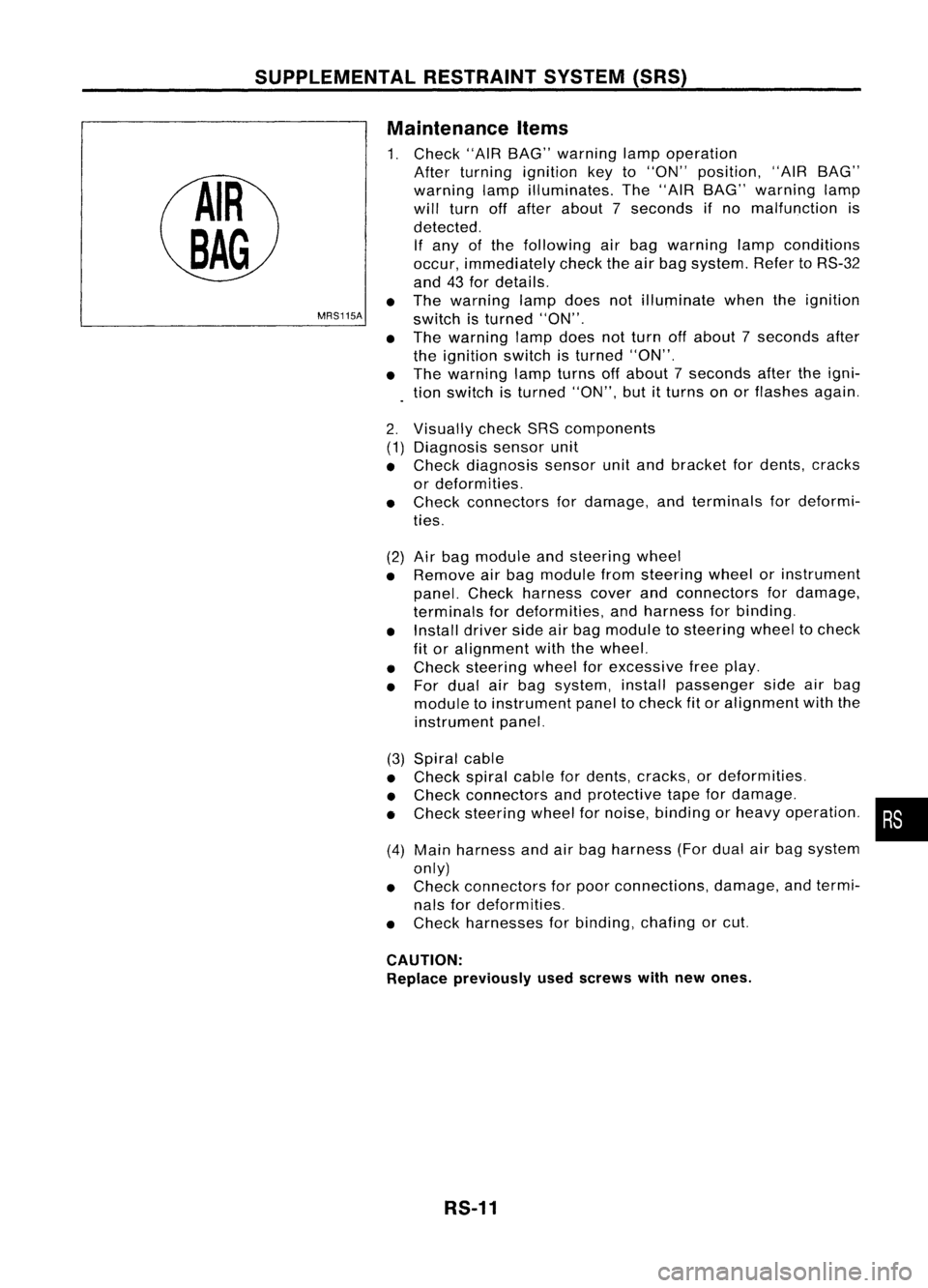
1. Check "AIRBAG" warning lampoperation
After turning ignition keyto"ON" position, "AIRBAG"
warning lampilluminates. The"AIR BAG" warning lamp
will turn offafter about 7seconds ifno malfunction is
detected. If any ofthe following airbag warning lampconditions
occur, immediately checktheairbag system. RefertoRS-32
and 43for details.
The warning lampdoesnotilluminate whentheignition
switch isturned "ON".
The warning lampdoesnotturn offabout 7seconds after
the ignition switchisturned "ON".
The warning lampturns offabout 7seconds aftertheigni-
tion switch isturned "ON",butitturns onorflashes again.
•
MRS115A
•
•
2. (1)
•
•
(2)
•
•
•
•
(3) Spiral cable
• Check spiralcablefordents, cracks, ordeformities.
• Check connectors andprotective tapefordamage.
• Check steering wheelfornoise, binding orheavy operation. •
(4) Main harness andairbag harness (Fordual airbag system
only)
• Check connectors forpoor connections, damage,andtermi-
nals fordeformities.
• Check harnesses forbinding, chafingorcut.
CAUTION: Replace previously usedscrews withnewones.
RS-11
Page 1638 of 1701
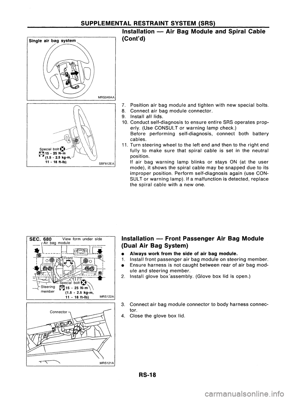
7.Position airbag module andtighten withnewspecial bolts.
8. Connect airbag module connector.
9. Install alllids.
10. Conduct self-diagnosis toensure entireSRSoperates prop-
erly. (Use CONSULT orwarning lampcheck.)
Before performing self-diagnosis, connectbothbattery
cables.
11. Turn steering wheeltothe leftend andthen tothe right end
fully tomake surethatspiral cableisset inthe neutral
position.
If air bag warning lampblinks orstays ON(atthe user
mode), itshows thespiral cablemaybesnapped duetoits
improper position.Performself-diagnosis again(useCON-
SUL Tor warning lamp).Ifa malfunction isdetected, replace
the spiral cablewithanew one.
SBF812EA
MRS046AA
SUPPLEMENTAL
RESTRAINTSYSTEM(SRS)
Installation -Air Bag Module andSpiral Cable
(Cont'd)
G\\
--------~
~\)
..~l~~
\\\?\\
Special bolt~~ "'(\\
cc:J
15-25 N.m ~
(1.5 -2.5 kg-m,
11 -18 ft-Ibl
Installation-Front Passenger AirBag Module
(Dual AirBag System)
• Always workfromtheside ofair bag module.
1. Install frontpassenger airbag module onsteering member.
• Ensure harness isnot caught between rearofair bag mod-
ule and steering member.
2. Install glovebox'assembly. (Gloveboxlidisopen.)
3. Connect airbag module connector tobody harness connec-
tor.
4. Close theglove boxlid.
RS-18
Page 1645 of 1701
TROUBLEDIAGNOSES -Supplemental RestraintSystem(SRS)
How toPerform TroubleDiagnoses forQuick
and Accurate Repair
A good understanding ofthe malfunction conditionscanmake troubleshooting fasterandmore accurate.
In general, eachcustomer feelsdifferently aboutaproblem. Itis important tofully understand the
symptoms orconditions foracustomer complaint.
INFORMATION FROMCUSTOMER
WHAT Vehiclemodel
WHEN Date,Frequencies
WHERE Roadconditions
HOW Operatingconditions, Symptoms
PRELIMINARY CHECK
Check thatthefollowing partsareingood" order.
• Battery [RefertoMA section ("GENERAL MAINTENANCE").]
• Fuse [Refer toEL section ("Fuse", "POWER SUPPLYROUTING").]
• System component-to-harness connections
DIAGNOSIS FUNCTION
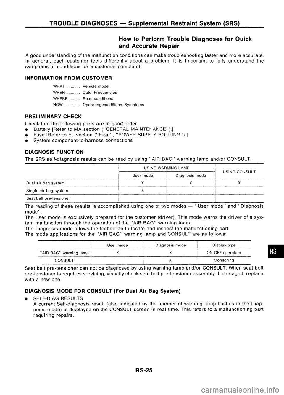
The SRS self-diagnosis resultscanberead byusing "AIRBAG" warning lampand/or CONSULT.
USING WARNING LAMP
USINGCONSULT
User mode Diagnosismode
Dual airbag system
X
X X
Single airbag system
X
Seat beltpre-tensioner
The reading ofthese results isaccomplished usingoneoftwo modes -"User mode" and"Diagnosis
mode".
The User mode isexclusively preparedforthe customer (driver).Thismode warns thedriver ofasys-
tem malfunction throughtheoperation ofthe "AIR BAG" warning lamp.
The Diagnosis modeallows thetechnician tolocate andinspect themalfunctioning part.
The mode applications forthe "AIR BAG" warning lampandCONSULT areasfollows:
User mode Diagnosis
mode Displaytype
"AIR BAG" warning lamp
X
X
ON-OFF
operation
CONSULT
X
Monitoring
Seat beltpre-tensioner cannotbediagnosed byusing warning lampand/or CONSULT. Whenseatbelt
pre-tensioner isrequires servicing, visuallycheckseatbeltpre-tensioner assembly.Ifdamaged, replace
with anew one.
DIAGNOSIS MODEFORCONSULT (ForDual AirBag System)
• SELF-DIAG RESULTS
A current Self-diagnosis result(alsoindicated bythe number ofwarning lampflashes inthe Diag-
nosis mode) isdisplayed onthe CONSULT screeninreal time. Thisrefers toamalfunctioning part
requiring repairs.
RS-25
•
Page 1647 of 1701
TROUBLEDIAGNOSES -Supplemental RestraintSystem(SRS)
How toPerform TroubleDiagnoses forQuick
and Accurate Repair(Cont'd)
CAUTION:
• Donot use acircuit testertocheck SRSharness connectors unlessinstructed tointhis Service
Manual. Fordual airbag system, SRSwiring harnesses arecovered withyellow insulation either
just before theharness connectors orfor complete harness,foreasy identification.
• Donot attempt torepair, spliceormodify theSRS wiring harness. Ifthe harness isdamaged, replace
it with anew one.
• Keep ground portionclean.
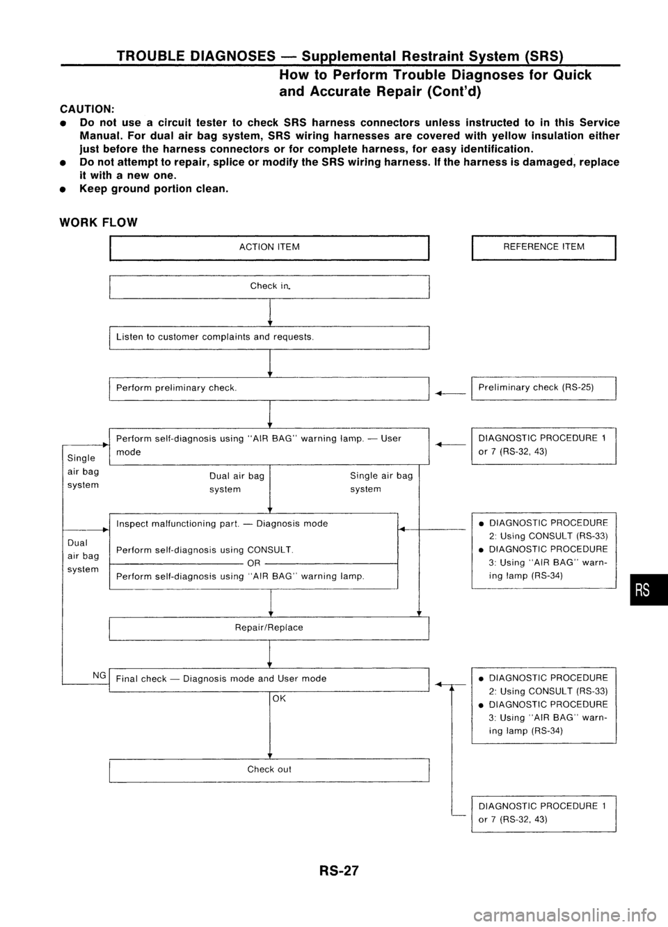
WORK FLOW
ACTIONITEM
Check in.
Listen tocustomer complaints andrequests.
Perform preliminary check. REFERENCE
ITEM
-+-1
Preliminary check(RS-25)
Perform self-diagnosis using"AIRBAG" warning lamp.-User
mode
Single
air bag
system Dual
airbag
system Single
airbag
system DIAGNOSTIC
PROCEDURE1
-+-
or7(RS-32, 43)
Dual
air bag
system Inspect
malfunctioning part.-Diagnosis mode
Perform self-diagnosis usingCONSULT.
OR
Perform self-diagnosis using"AIRBAG" warning lamp.
Repair/Replace •
DIAGNOSTIC PROCEDURE
2: Using CONSULT (RS-33)
• DIAGNOSTIC PROCEDURE
3: Using "AIRBAG" warn-
ing lamp (RS-34)
•
NG Final check -Diagnosis modeandUser mode
OK
Check out
RS-27 •
DIAGNOSTIC PROCEDURE
2: Using CONSULT (RS-33)
• DIAGNOSTIC PROCEDURE
3: Using "AIRBAG" warn-
ing lamp (RS-34)
DIAGNOSTIC PROCEDURE1
or 7(RS-32, 43)
Page 1648 of 1701
TROUBLEDIAGNOSES -Supplemental RestraintSystem(SRS)-
Dual AirBag System
Schematic
FUSE
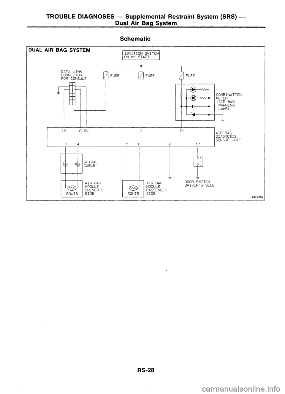
DUAL
AIRBAG SYSTEM
DATA LINK
CONNECTOR
FOR CONSULT
o
FUSE
COMBINAnON
METER
(AIR BAG
WARNING
LAMP)
19
3
2120
4
5
6
2
15
17
AIR
BAG
DIAGNOSIS
SENSOR UNIT
SPIRAL
CABLE
AIR BAG
MODULE
DRIVER'S
SQUIB SIDE AIR
BAG
MODULE
PASSENGER
SQUIB SIDE
RS-28
-
DOOR SWITCH
DRIVER'S SIDE
HRS002
Page 1649 of 1701
TROUBLEDIAGNOSES -Supplemental RestraintSystem(SRS)-
Dual AirBag System
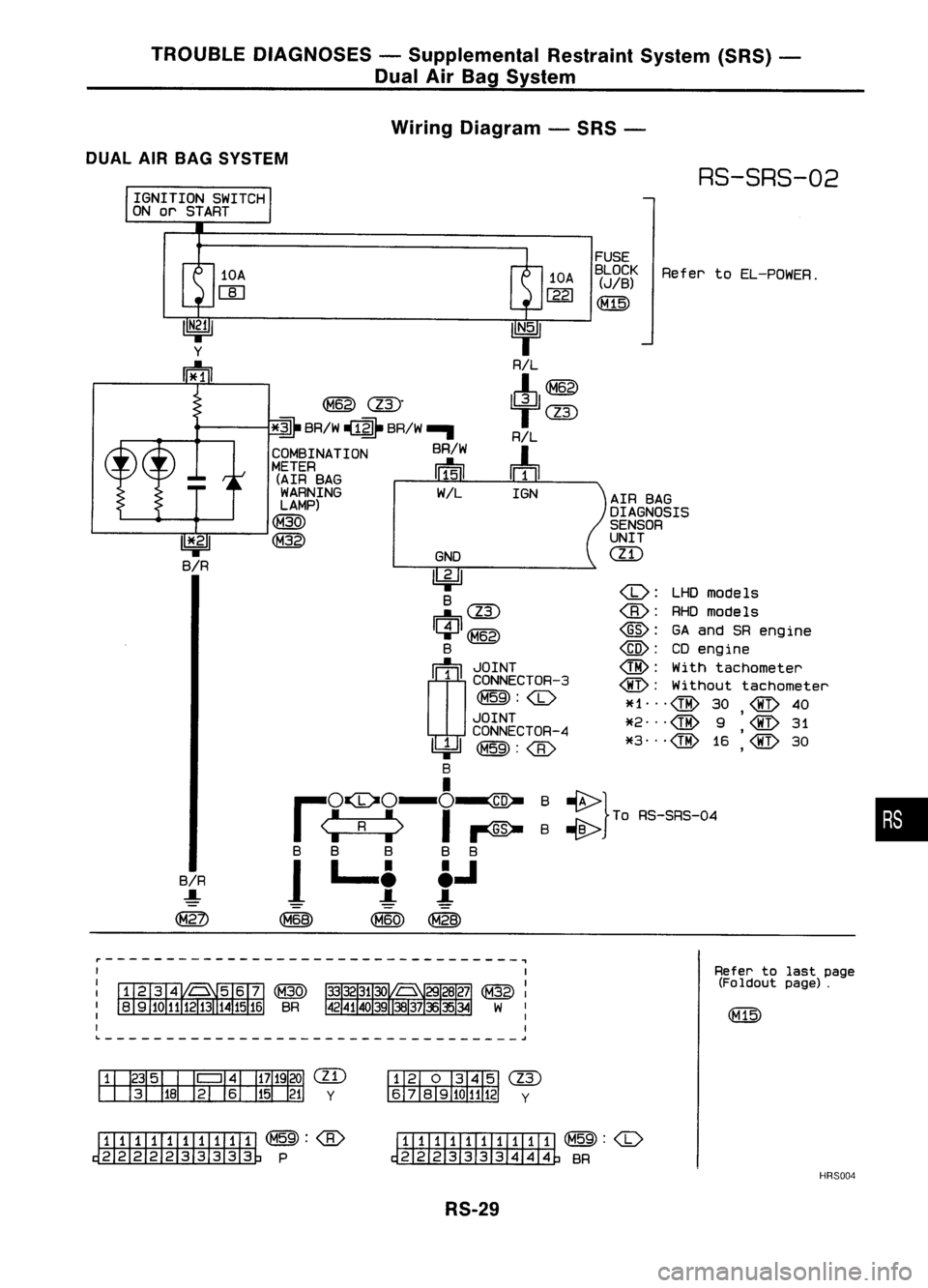
Wiring Diagram -SRS -
DUAL AIRBAG SYSTEM
RS-SRS-02
IGNITION SWITCH
ON orSTART
::} ToAS-SAS-D.
•
Refer
toEL-POWER.
LHOmode Is
RHOmodels
@:
GAand SRengine
@:
CDengine
@:
Withtachometer
@:
Without tachometer
~f1 ...
@
30
@
40
,
*2
@
9
@
31
*3
@
16
'@
30
,
AIR
BAG
DIAGNOSIS
SENSOR
UNIT
ill)
FUSE
BLOCK
(JIB)
(M15)
10A
1221
IGN
GNO
~ B
~(ll)
C:J~
B
rn~
I
~g~~~CTOR-3
~:
JOINT
CONNECTOR-4
~~:
I
,..O~O-O-ID-
I
<:
R
:>
I~
B B B BB
1
L..t t.J
~ (M60)~
~
(ll)"
*~
BRIW ~ BRIW-.
COMBINATION BRIW
METER ~
(AIR BAG 111511
WARNING WIL
LAMP)
(M30)
~
10A
W
BIR
.....
~
11*.21
BIR
~----------------------------------~
Refertolast page
(Foldout page).
L ~
em
y
(IT)
y
~(M59):
~P
ITIII:illJIIIII
~:
~ BR
HRS004
RS-29
Page 1652 of 1701
TROUBLEDIAGNOSES -Supplemental RestraintSystem(SRS)-
Dual AirBag System
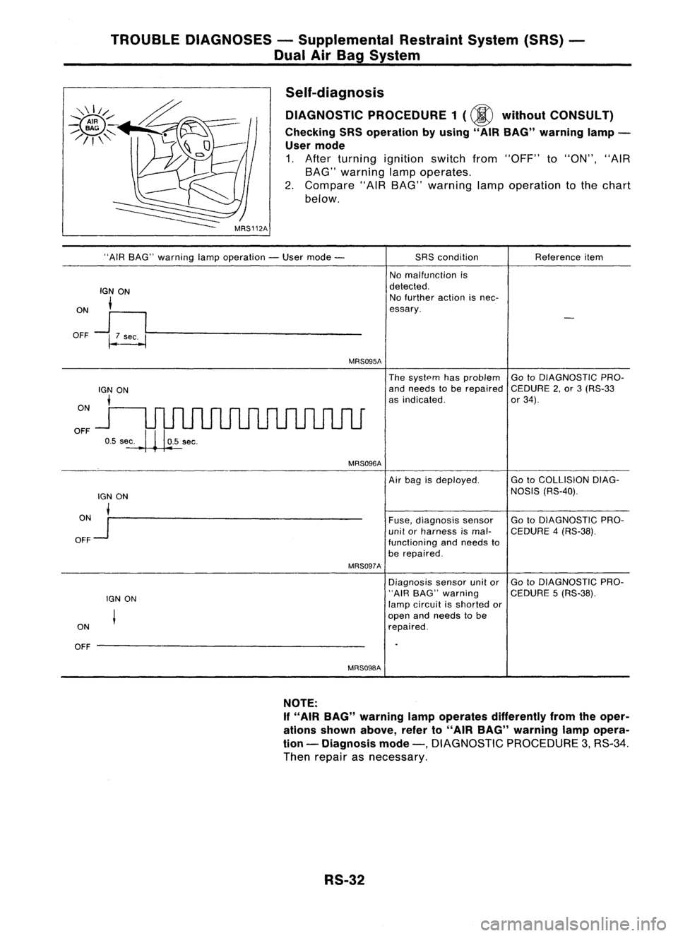
Self-diagnosis DIAGNOSTIC PROCEDURE 1(@ without CONSULT)
Checking SRSoperation byusing" AIRBAG" warning lamp-
User mode
1. After turning ignition switchfrom"OFF" to"ON", "AIR
BAG" warning lampoperates.
2. Compare "AIRBAG" warning lampoperation tothe chart
below.
"AIR BAG" warning lampoperation -User mode -
IGN ON
i
ON
J
I
OFF ~~----------------
MRS095A
SRS
condition
No malfunction is
detected. No further actionisnec-
essary. Reference
item
ON
OFF
The
system hasproblem GotoDIAGNOSTIC PRO-
and needs tobe repaired CEDURE2,or 3(RS-33
as indicated. or34).
MRS096A
lGN ON
ON •
OFF
Jr--------------------
MRS097A
IGN ON
ON
OFF --------------------
MRS098A
Air
bag isdeployed. GotoCOLLISION DIAG-
NOSIS (RS-40).
Fuse, diagnosis sensor GotoDIAGNOSTIC PRO-
unit orharness ismal- CEDURE 4(RS-38).
functioning andneeds to
be repaired.
Diagnosis sensorunitor GotoDIAGNOSTIC PRO-
"AIR BAG" warning CEDURE5(RS-38).
lamp circuit isshorted or
open andneeds tobe
repaired.
NOTE:
If "AIR BAG" warning lampoperates differently fromtheoper-
ations shown above, referto"AIR BAG" warning lampopera-
tion -Diagnosis mode-,
DIAGNOSTIC PROCEDURE3,RS-34.
Then repair asnecessary.
RS-32