1995 NISSAN ALMERA N15 service
[x] Cancel search: servicePage 373 of 1701

ELECTRICALSYSTEM
SECTION
EL
When youread wiring diagrams:
• Read GIsection, "HOWTOREAD WIRING DIAGRAMS".
When youperform troublediagnos.es, readGIsection, "HOWTOFOllOW FLOWCHART
IN TROUBLE DIAGNOSES" and"HOW TOPERFORM EFFICIENT DIAGNOSIS FORAN
ELECTRICAL INCIDENT".
CONTENTS
PRECAUTIONS 4
Supplemental RestraintSystem(SRS)"AIR
BAG" (DualAirBag System) 4
Supplemental RestraintSystem(SRS)"AIR
BAG" (Single AirBag System) 4
HARNESS CONNECTOR 5
Description 5
STANDARDIZED RELAy 6
Description 6
POWER SUPPLY ROUTING 8
Schematic 8
Wiring Diagram -POWER - 10
Fuse 19
Fusible Link 19
Circuit Breaker 19
GROUND DISTRIBUTION 20
BATTERy 25
How toHandle Battery 25
Battery TestandCharging Chart.. 28
Service DataandSpecifications (SOS) 32
STARTING SySTEM
33
Wiring Diagram -START - 33
Trouble Diagnoses 35
Construction 36
Removal andInstallation .45
Magnetic SwitchCheck .46
Pinion/Clutch Check 46
Brush Check 46
Yoke Check 47
Armature Check 48
Assembly .49
Service DataandSpecifications (SDS) 50
CHARGING SYSTEM 52
Wiring Diagram -CHARGE - 52
Trouble Diagnoses 54Construction
55
Removal andInstallation 57
Disassembly 57
Rotor Check 57
Brush Check 58
Stator Check 58
Diode Check 59
Assembly 60
Service DataandSpecifications (SDS) 61
COMBINATION SWITCH 62
Combination Switch/Check 62
Replacement 64
HEADLAMP -Without Daytime lightSystem -65
Wiring Diagram -H/LAMP - 65
Trouble Diagnoses 67
HEADLAMP -Daytime lightSystem - 68
Operation (Daytimelightsystem) 68
System Description 69
Schematic 70
Wiring Diagram -DTRL - 71
Trouble Diagnoses (DaytimeLight) 74
HEADLAMP 75
Bulb Replacement... 75•
Aiming Adjustment. 75
HEADLAMP -Headlamp Aiming
Control- 77
Wiring Diagram -AIM - 77
Description 81
EXTERIOR LAMP 82
Clearance, LicenseandTail Lamps/Schematic 82
Clearance, LicenseandTail Lamps/Wiring
Diagram -TAILIL - 83
Stop Lamp/Wiring Diagram-STOP/L - 92
Back-up Lamp/Wiring Diagram-BACK/L -94
Front FogLamp/Wiring Diagram-F/FOG -96
Front FogLamp BulbReplacement 101
Page 376 of 1701
PRECAUTIONS
Supplemental RestraintSystem(SRS)"AIR
BAG" (DualAirBag System)
The Supplemental RestraintSystem"AirBag", usedalong withaseat belt,helps toreduce therisk or
severity ofinjury tothe driver andfront passenger inafrontal collision. TheSupplemental Restraint
System consists ofair bag modules (locatedinthe center ofthe steering wheelandonthe instrument
panel onthe passenger side),adiagnosis sensorunit,warning lamp,wiring harness andspiral cable.
Information necessarytoservice thesystem safelyisincluded inthe
RSsection
ofthis Service Manual.
WARNING:
• Toavoid rendering theSRS inoperative, whichcouldincrease therisk ofpersonal injuryordeath
in the event ofacollision whichwould resultinair bag inflation, allmaintenance mustbeperformed
by an authorized NISSANdealer.
• Improper maintenance, includingincorrectremovalandinstallation ofthe SRS, canlead topersonal
injury caused byunintentional activationofthe system.
• Donot use electrical testequipment onany circuit related tothe SRS unless instructed tointhis
Service Manual. SRSwiring harnesses arecovered withyellow insulation eitherjustbefore the
harness connectors orfor the complete harness,foreasy identification.
Supplemental RestraintSystem(SRS)"AIR
BAG" (Single AirBag System)
The Supplemental RestraintSystem"AirBag", usedalong withaseat belt,helps toreduce therisk or
severity ofinjury tothe driver inafrontal collision. TheSupplemental RestraintSystemconsists ofan
air bag module (located inthe center ofthe steering wheel),adiagnosis sensorunit,warning lampand
spiral cable. Information necessarytoservice thesystem safelyisincluded inthe
RSsection
ofthis
Service Manual.
WARNING: • Toavoid rendering theSRS inoperative, whichcouldincrease therisk ofpersonal injuryordeath
in the event ofacollision whichwould resultinair bag inflation, allmaintenance mustbeperformed
by an authorized NISSANdealer.
• Improper maintenance, includingincorrectremovalandinstallation ofthe SRS, canlead topersonal
injury caused byunintentional activationofthe system.
• Donot use electrical testequipment onany circuit related tothe SRS.
EL-4
Page 404 of 1701
I
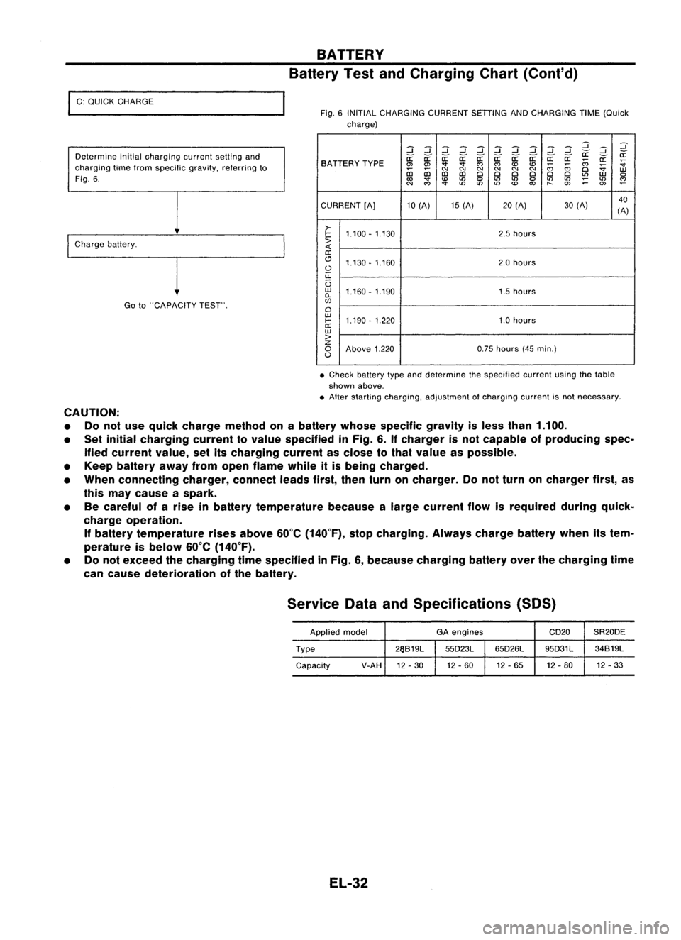
C: QUICK CHARGE
Determine initialcharging currentsettingand
charging timefrom specific gravity,referring to
Fig. 6.
I
Charge battery.
Goto"CAPACITY TEST".
BATTERY
Battery TestandCharging Chart(Cont'd)
Fig. 6INITIAL CHARGING CURRENTSETTINGANDCHARGING TIME(Quick
charge)
:::J:::J:::J:::J :::J:::J:::J
d dd
:::J
:::J :::J
~ ~
SA TTERY TYPE
~
~ ~~~~ ~a: a:a:
;;:;
~
~
0>
0>
""
""
C')
C')
CDCD
;;:;
;;:;
~
co co
C\I
N
C\I
N
C\I
N
Cl
W
D:l D:l
ClCl ClCl ClCl
L()
W
0
to
""
CD
L()
0
L()
L()
0
L()
L()
;:
L()
~
N
C')
""
L()
L()L()
CD
to
t-
O>
0>
CURRENT [A]10(A) 15(A) 20(A) 30(A) 40
(A)
>-
I-
1.100 -1.130 2.5
hours
:>
a:
(!J 1.130 -1.160 2.0
hours
0
u::
U
w
1.160 -1.190 1.5hours
0-
w
Cl
w
1.190 -1.220 1.0hours
I-
a:
w
>
z
0
Above 1.220 0.75
hours (45min.)
0
• Check battery typeanddetermine thespecified currentusingthetable
shown above.
• After starting charging, adjustment ofcharging currentisnot necessary.
CAUTION: • Donot use quick charge method onabattery whosespecific gravityisless than 1.100.
• Set initial charging currenttovalue specified inFig. 6.Ifcharger isnot capable ofproducing spec-
ified current value,setitscharging currentasclose tothat value aspossible.
• Keep battery awayfromopen flame whileitis being charged.
• When connecting charger,connectleadsfirst,thenturnoncharger. Donot turn oncharger first,as
this may cause aspark.
• Becareful ofarise inbattery temperature becausealarge current flowisrequired duringquick-
charge operation.
If
battery temperature risesabove 60°C(140°F), stopcharging. Alwayschargebatterywhenitstem-
perature isbelow 60°C(140°F).
• Donot exceed thecharging timespecified inFig. 6,because charging batteryoverthecharging time
can cause deterioration ofthe battery.
Service DataandSpecifications (SOS)
Applied model GA
engines CD20SR20DE
Type 26S19L
55D23L65D26L 95D31L
34S19L
Capacity V-AH
12-30 12
-60 12-65 12-80 12
-33
EL-32
Page 422 of 1701
STARTINGSYSTEM
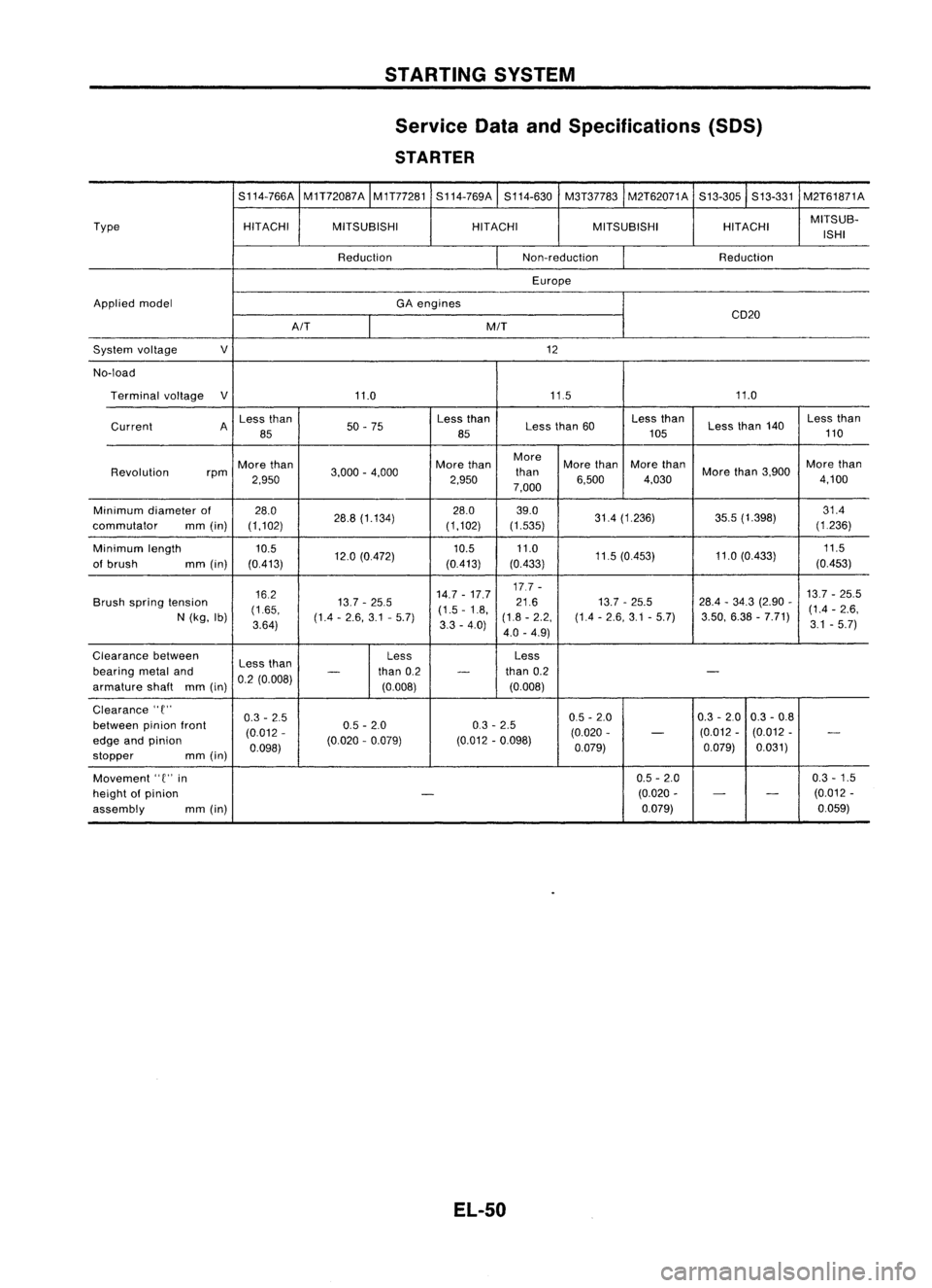
Service DataandSpecifications (SDS)
STARTER
S114-766A M1T72087A
M1T77281S114-769A S114-630M3T37783 M2T62071A S13-305S13-331M2T61871A
Type HITACHIMITSUBISHI HITACHI
MITSUBISHI HITACHIMITSUB-
ISHI
Reduction Non-reduction
Reduction
Europe
Applied model
GAengines
CD20
A/T MIT
System voltage
V
12
No-load Terminal voltage
V
11.0 11511.0
Less than
50-75 Less
than
Lessthan60 Less
than
Lessthan140 Less
than
Current A
85 85105110
More than Morethan More
Morethan More
than Morethan
Revolution rpm
2,950 3,000
-4,000
2,950than
6,500 4,030More
than3,900
4,100
7,000
Minimum diameterof 28.0
28.8(1.134) 28.0
39.0
31.4(1.236) 35.5(1.398) 31.4
commutator mm(in) (1,102) (1,102)(1.535) (1236)
Minimum length
10.5 10.511.0
11.5(0.453) 11.0
(0.433) 11.5
of brush mm(in) (0.413) 12.0
(0.472)
(0.413)(0.433) (0.453)
16.2 14.7
-17.7 17.7
-
13.7-25.5
Brush spring tension
(1.65, 13.7
-25.5
(1.5-1.8, 21.6
13.7-25.5 28.4
-34.3 (2.90 -
(1.4 -2.6,
N (kg, Ib)
3.64) (1.4
-2.6, 3.1-5.7)
3.3-4.0) (1.8
-2.2, (1.4-2.6, 3.1-5.7) 3.50,
6.38-7.71)
3.1-5.7)
4.0 -4.9)
Clearance between
Lessthan Less
Less
bearing metaland
-
than0.2
-
than
0.2
-
armature shaftmm(in) 0.2
(0.008)
(0.008) (0.008)
Clearance
'T'
0.3-2.5 0.5
-2.0 0.3-2.0 0.3
-0.8
between pinionfront
(0.012- 0.5
-2.0 0.3-2.5
(0.020- (0.012
-(0.012 -
- -
edge andpinion
0.098)(0.020
-0.079) (0.012
-0.098)
0.079) 0.079)0.031)
stopper mm
(in)
Movement
'T'
in 0.5
-2.0 0.3
-1.5
height ofpinion
-
(0.020
-
-
-
(0.012
-
assembly mm(in) 0.079)0.059)
EL-50
Page 423 of 1701
STARTINGSYSTEM
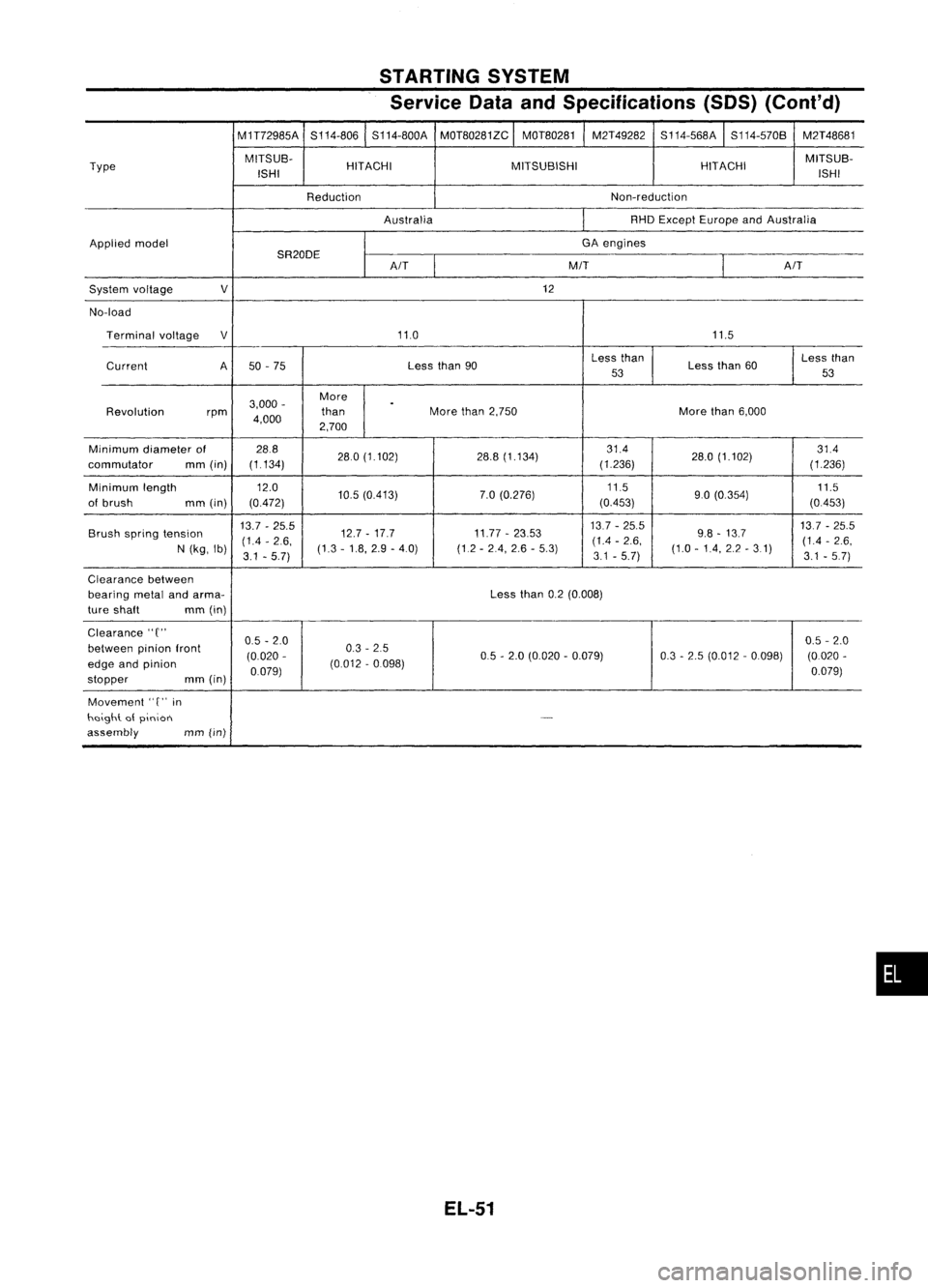
Service DataandSpecifications (SOS)(Cont'd)
M1T72985A S114-806S114-800A
MOT80281ZC
I
MOT80281 M2T49282
S114-568A
I
S114-570B M2T48681
Type MITSUB-
HITACHI MITSUBISHI HITACHIMITSUB-
ISH I ISHI
Reduction Non-reduction
Australia RHD
Except Europe andAustralia
Applied model GA
engines
SR20DE
I
A/T
M/T
AIT
System voltage
V
12
No-load Terminal voltage
V
11.0 11.5
Current A50-75 Less
than90 Less
than
Lessthan60 Less
than
53 53
3,000 - More
.
Revolution rpm
4,000 than
More
than2,750 Morethan6,000
2,700
Minimum diameterof 28.8
280(1.102) 28.8(1.134) 314
28.0(1.102) 314
commutator mm(in) (1.134)
(1.236)
(1236)
Minimum length 12.0
10.5(0413) 7.0
(0.276) 11.5
90(0.354) 11.5
of brush mm(in) (0472) (0453)
(0453)
Brush spring tension 13.7
-25.5
12.7-17.7 11.77-23.53 13.7
-25.5
9.8-13.7 137
-25.5
(14 -2.6, (14
-2.6, (1.4-2.6,
N (kg, Ib)
3.1-5.7) (1.3
-1.8, 2.9-4.0) (1.2-24, 2.6-5.3)
3.1-5.7) (1.0
-14, 2.2-31)
3.1.5.7)
Clearance between
bearing metalandarma- Lessthan0.2(0.008)
ture shaft mm(in)
Clearance"
C"
0.5-2.0 0.5
-2.0
between pinionfront
(0.020- 0.3
-25
05-2.0 (0.020 -0.079) 0.3-2.5 (0.012 -0.098) (0.020-
edge andpinion
0.079)(0.012
-0.098)
0.079)
stopper mm
(in)
Movement
'T'
in
heigh\. atpinion
-
assembly
mm(in)
EL-51
•
Page 433 of 1701
CHARGINGSYSTEM
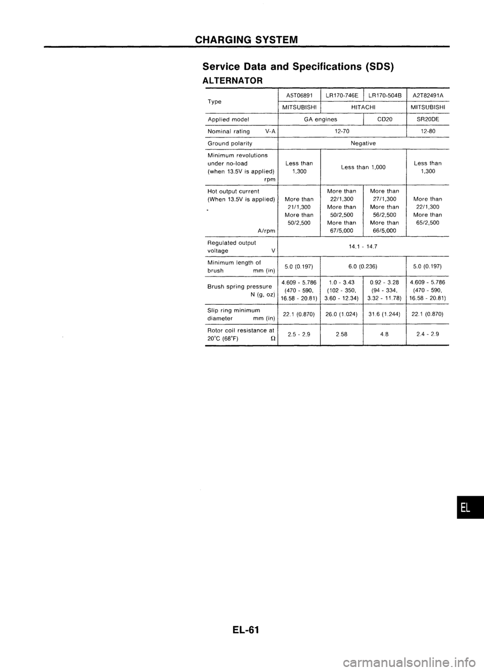
Service DataandSpecifications (SOS)
ALTERNATOR
A5T06891LR170-746E LR170-504B A2T82491A
Type MITSUBISHIHITACHIMITSUBISHI
Applied model GA
engines CD20SR20DE
Nominal rating V-A
12-70 12-80
Ground polarity Negative
Minimum revolutions
under no-load Less
than
Lessthan1,000 Less
than
(when 13.5Visapplied) 1,300 1,300
rpm
Hot output current More
than Morethan
(When 13.5Visapplied) More
than 22/1,300 27/1,300
Morethan
.
21/1,300
Morethan More
than 22/1,300
More than 50/2,500 56/2,500More
than
50/2,500 Morethan Morethan 65/2,500
A/rpm 67/5,000
66/5,000
Regulated output
14.1-14.7
voltage V
Minimum lengthof
50(0.197) 6.0
(0.236) 5.0(0.197)
brush mm(in)
Brush spring pressure 4.609
-5.786 1.0-343 0.92
-328 4.609-5.786
(470 -590, (102
-350, (94-334, (470
-590,
N (g, oz)
16.58 -20.81) 3.60
-12.34) 332-11.78) 16.58
-20.81)
Slip ringminimum
221(0.870) 26.0
(1.024) 31.6(1.244) 221(0.870)
diameter mm(in)
Rotor coilresistance at
2.5-2.9 258 4824
-29
20'C (68'F)
n
EL-61
•
Page 623 of 1701
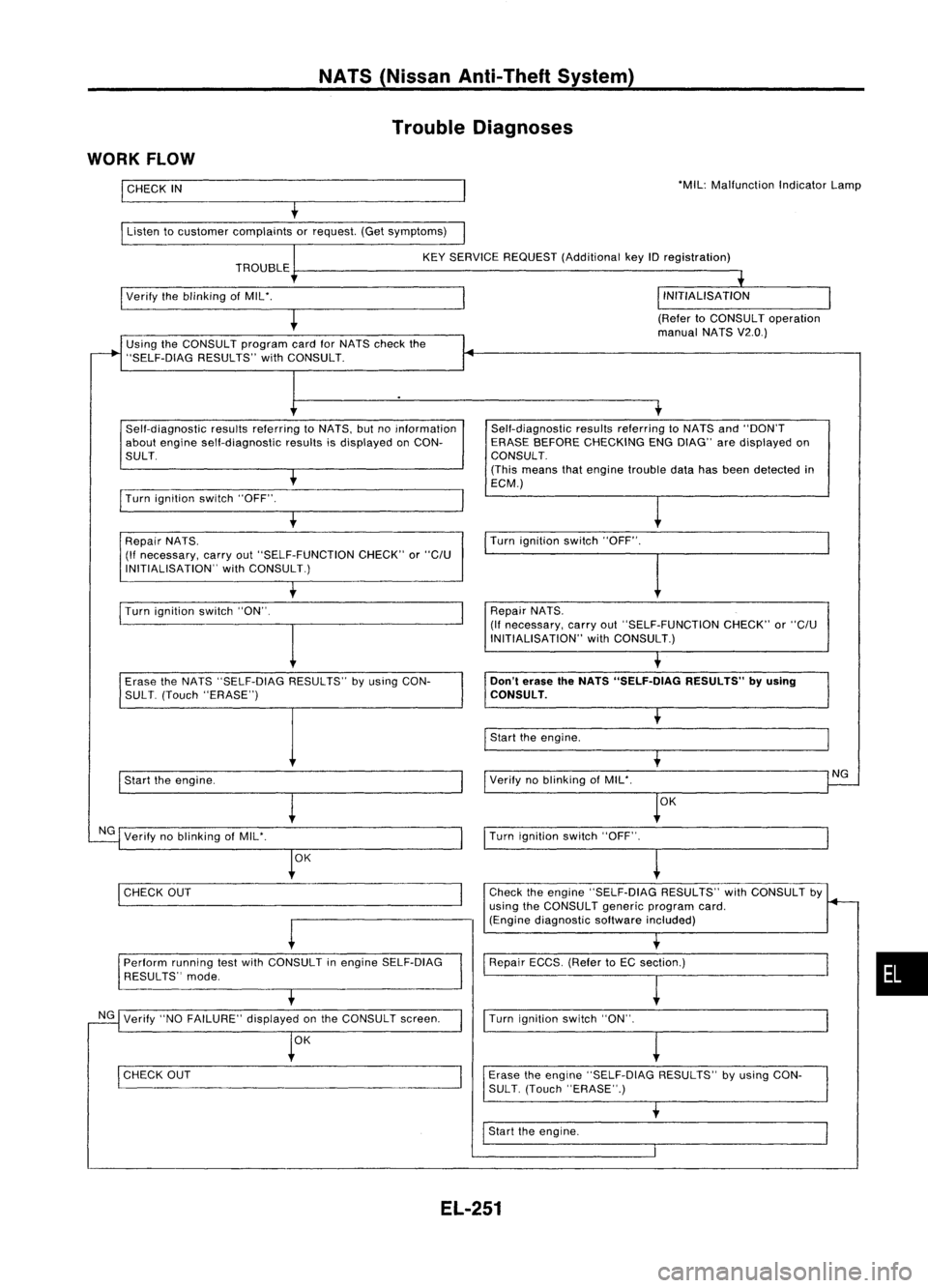
NATS(Nissan Anti-Theft System)
Trouble Diagnoses
WORK FLOW
I
CHECK
IN
Listen tocustomer complaints orrequest. (Getsymptoms) 'MIL:
Malfunction IndicatorLamp
KEY SERVICE REQUEST (Additional keyIDregistration)
TROUBLE
I
Verify theblinking ofMIL'.
(RefertoCONSULT operation
manual NATSV2.0.)
Using theCONSULT programcardforNATS check the
"SELF-DiAG RESULTS"withCONSULT.
Self-diagnostic resultsreferring toNATS, butnoinformation
about engine self-diagnostic resultsisdisplayed onCON-
SULT.
I
Turn ignition switch"OFF".
t
Repair NATS.
(If necessary, carryout"SELF-FUNCTION CHECK"or
"C/U
INITIALISATION" withCONSULT.) Self-diagnostic
resultsreferring toNATS and"DON'T
ERASE BEFORE CHECKING ENGDIAG" aredisplayed on
CONSULT.
(This means thatengine trouble datahasbeen detected in
ECM.)
Turn ignition switch"OFF".
I
Turn ignition switch"ON".
I
Repair
NATS.
(If necessary, carryout"SELF-FUNCTION CHECK"or
"C/U
INITIALISATION" withCONSULT.)
Erase theNATS "SELF-DIAG RESULTS"byusing CON-
SUL T.(Touch "ERASE")
I
Start theengine.
NG Verify noblinking ofMIL'.
OK
I
CHECK OUT
-
Perform runningtestwith CONSULT inengine SELF-DiAG
RESULTS" mode.
NG Verify "NOFAILURE" displayedonthe CONSULT screen.
OK
I
CHECK OUT
Don't
erase theNATS "SELF.DlAG RESULTS"byusing
CONSULT.
I
Start theengine.
Verify noblinking ofMIL'.
OK
I
Turn ignition switch"OFF".
~
Check theengine "SELF-DiAG RESULTS"withCONSULT by
using theCONSULT genericprogram card.
(Engine diagnostic softwareincluded)
Repair ECCS.(RefertoEC section.)
I
Turn ignition switch"ON".
Erase theengine "SELF-DIAG RESULTS"byusing CON-
SUL T.(Touch "ERASE".)
I
Start theengine.
NG
•
EL-251
Page 683 of 1701
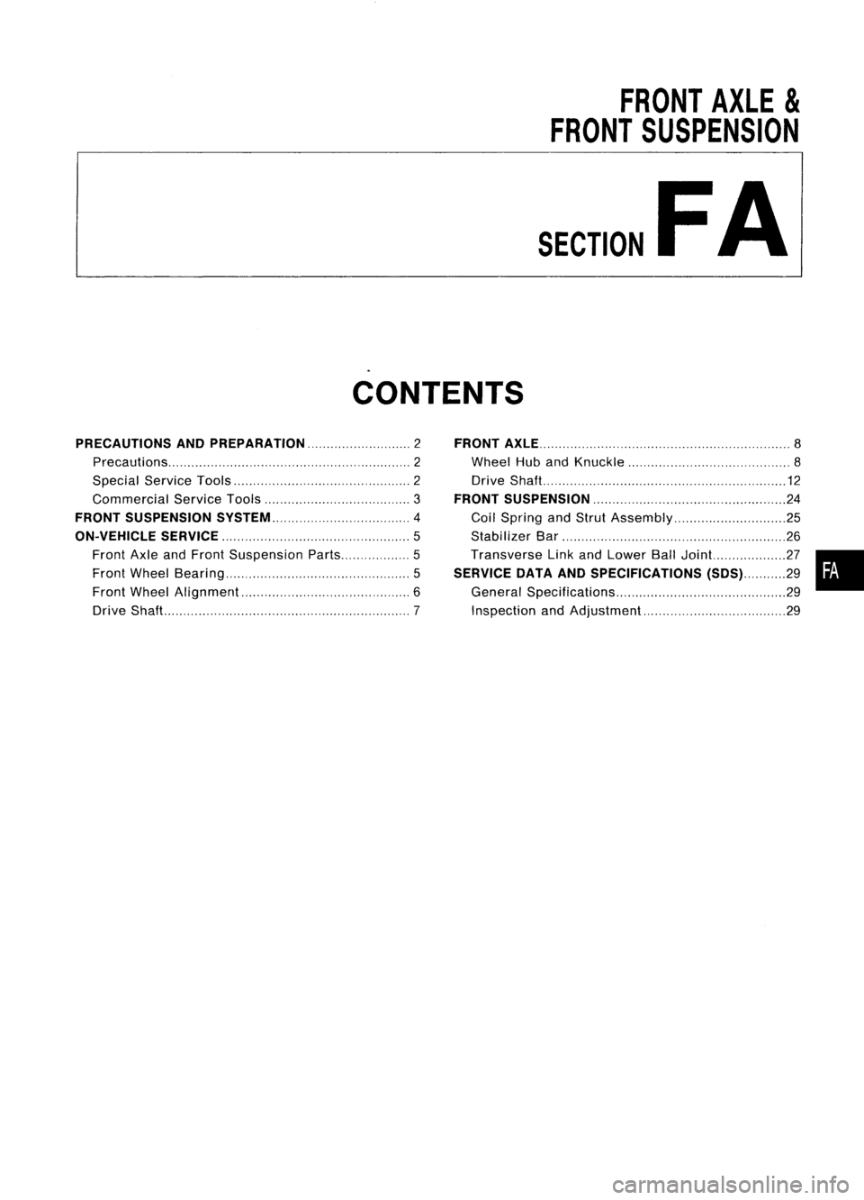
FRONTAXLE
&
FRONT SUSPENSION
SECTION
FA
CONTENTS
PRECAUTIONS ANDPREPARATION 2
Precautions 2
Special ServiceTools 2
Commercial ServiceTools 3
FRONT SUSPENSION SySTEM 4
ON-VEHICLE SERVICE
5
Front AxleandFront Suspension Parts 5
Front Wheel Bearing 5
Front Wheel Alignment.. 6
Drive Shaft 7FRONT
AXLE 8
Wheel HubandKnuckle 8
Drive Shaft 12
FRONT SUSPENSION 24
Coil Spring andStrut Assembly 25
Stabilizer Bar 26
Transverse LinkandLower BallJoint.. 27•
SERVICE DATAANDSPECIFICATIONS (SDS)29
General Specifications 29
Inspection andAdjustment 29