1995 NISSAN ALMERA N15 service
[x] Cancel search: servicePage 714 of 1701
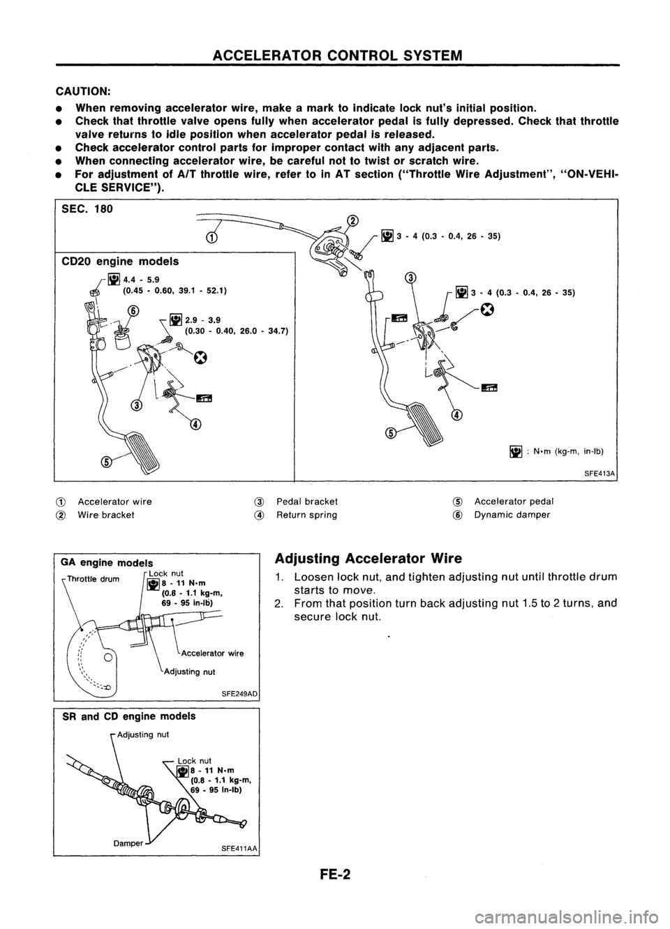
ACCELERATORCONTROLSYSTEM
CAUTION:
• When removing accelerator wire,make amark toindicate locknut's initial position.
• Check thatthrottle valveopens fullywhen accelerator pedalisfUlly depressed. Checkthatthrottle
valve returns toidle position whenaccelerator pedalisreleased.
• Check accelerator controlpartsforimproper contactwithanyadjacent parts.
• When connecting accelerator wire,becareful nottotwist orscratch wire.
• For adjustment ofAfT throttle wire,refertoinAT section ("Throttle WireAdjustment", "ON-VEHI-
CLE SERVICE").
SEC. 180
SFE413A
iii
:
N'm (kg-m, in-Ib)
5
~~
Iii]
3.4 (0.3 .0.4, 26.36)
~~~
5
CD20
engine models
r
1iI4.4 •5.9
~ (0.45-0.60, 39.1•52.1)
\i
v'
!il2.9-3.9
~ (0.30-0.40, 26.0-34.7)
7C
A~
~'
.
.
~
3l~
,
G)
Accelerator wire
@
Wire bracket
@
Pedal bracket
@
Return spring
CID
Accelerator pedal
@
Dynamic
damper
SFE249AD
GA
engine models
Locknut
~8 -11N.m
(0.8 -1.1 kg-m,
69 -95 in-Ib)
Adjusting
Accelerator Wire
1. Loosen locknut,andtighten adjusting nutuntil throttle drum
starts tomove.
2. From thatposition turnback adjusting nut1.5to2turns, and
secure locknut.
SR and CDengine models
Lock nut
• 8-11 N.m
(0.8 -1.1 kg-m,
69 -95 In-Ib)
SFE411AA FE-2
Page 715 of 1701
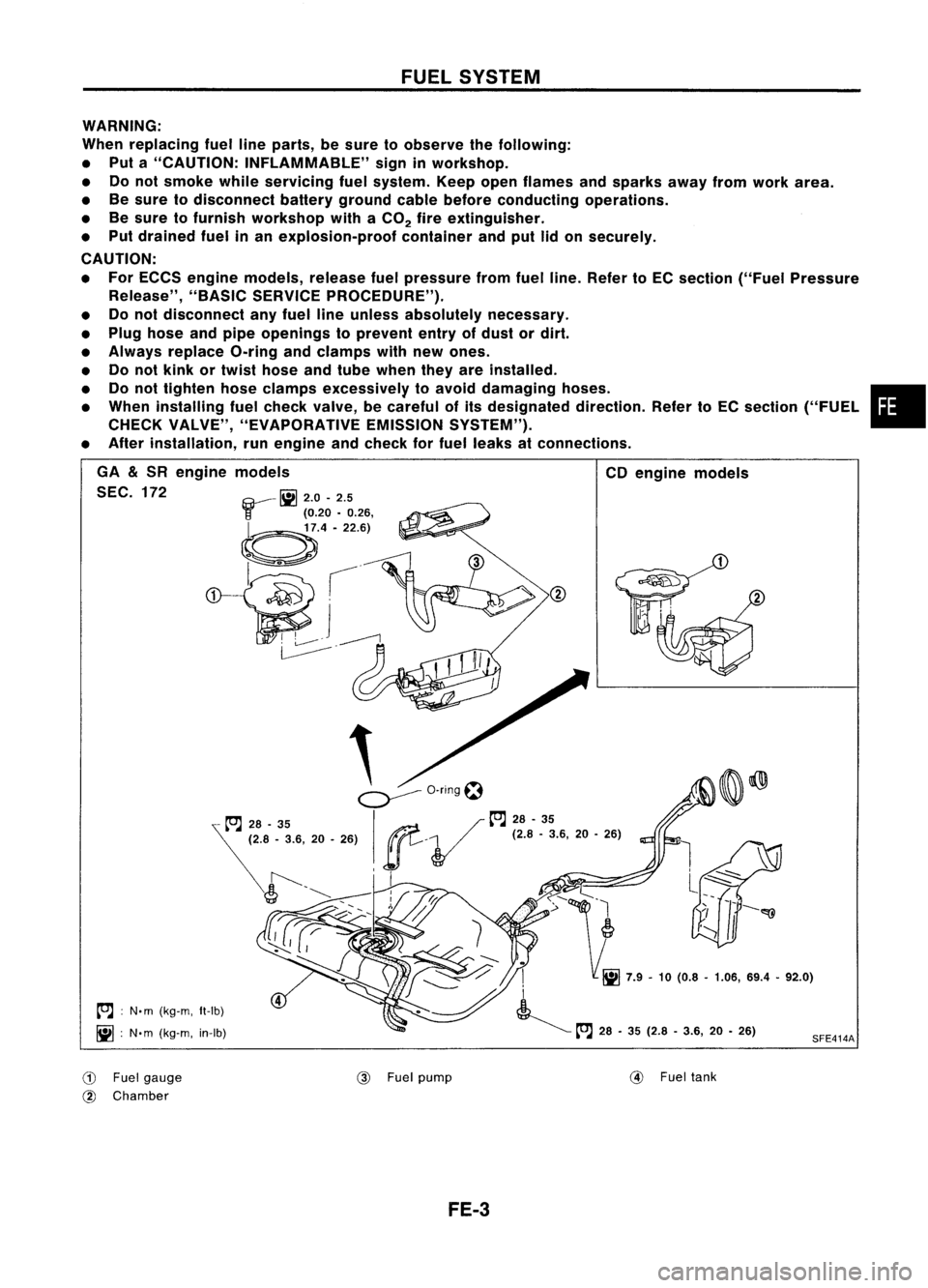
FUELSYSTEM
WARNING:
When replacing fuellineparts, besure toobserve thefollowing:
• Put a"CAUTION: INFLAMMABLE" signinworkshop.
• Donot smoke whileservicing fuelsystem. Keepopenflames andsparks awayfromwork area.
• Besure todisconnect batterygroundcablebefore conducting operations.
• Besure tofurnish workshop withaCO
2
fireextinguisher.
• Put drained fuelinan explosion-proof containerandputlidon securely.
CAUTION:
• For ECCS engine models, releasefuelpressure fromfuelline. Refer toEC section ("FuelPressure
Release", "BASICSERVICE PROCEDURE").
• Donot disconnect anyfuel lineunless absolutely necessary.
• Plug hose andpipe openings toprevent entryofdust ordirt.
• Always replace O-ringandclamps withnewones.
• Donot kink ortwist hose andtube when theyareinstalled.
• Donot tighten hoseclamps excessively toavoid damaging hoses. •
• When installing fuelcheck valve, becareful ofits designated direction.RefertoEC section ("FUEL
CHECK VALVE", "EVAPORATIVE EMISSIONSYSTEM").
• After installation, runengine andcheck forfuel leaks atconnections.
SFE414A
CD
engine models
.
I
i
~ tt'.J
28•35 (2.8 -3.6, 20•26)
,
.
~o-nngt:1
...,/ tt'.J
28-35
ge.
V
(2.'.3.6, 20•26)
, I
GA
&
SR engine models
SEC. 172 ~
2.0-2.5
r
(0.20•0.26,
~.4'22.6)
~ .---£l
~I
~j~
~.
tt'.J :
N. m (kg-m, It-Ib)
iii :
N'm (kg-m, in-Ib)
CD
Fuelgauge
@ Chamber @
Fuelpump
@
Fueltank
FE-3
Page 720 of 1701
ENGINECONTROL SYSTEM
SECTION
EC
CONTENTS
•
PRECAUTIONS ANDPREPARATION
4
Special Service Tools 4
Supplemental RestraintSystem(SRS)"AIR
BAG" (DualAirBag System) 7
Supplemental RestraintSystem(SRS)"AIR
BAG" (Single AirBag System) 7
GA,SR
PRECAUTIONS ANDPREPARATION
8
Engine Fuel
&
Emission ControlSystem 8
Precautions forECCS Trouble Diagnosis of
Engine 9
Precautions 9
ENGINE ANDEMISSION CONTROLOVERALL
SYSTEM 11
Circuit Diagram -Except forAustralia 11
Circuit Diagram -For Australia 12
System Diagram -GA 14DE, GA16DE for
Europe andIsrael 13
System Diagram -GA15DE 14
System Diagram -GA 16DE except for
Europe, IsraelandAustralia 15
System Diagram -GA 16DE forAustralia 16
ECCS Component PartsLocation -GA 14DE,
GA 16DE forEurope andIsrael 17
ECCS Component PartsLocation -GA15DE 18
ECCS Component PartsLocation -GA 16DE
except forEurope, IsraelandAustralia 19
ECCS Component PartsLocation -GA 16DE
for Austral ia 20
ECCS Component PartsLocation 21
Vacuum HoseDrawing 22
c=
~
GA
ENGINE
ANDEMISSION BASICCONTROL
SYSTEM DESCRiPTION 23
System Chart.. 23
Multiport FuelInjection (MFI)System 24
Distributor Ignition(01)System 27
Air Conditioning CutControl 28
Fuel CutControl (atnoload &high engine
speed) 28
EVAPORATIVE EMISSIONSYSTEM
29
Inspection 29
POSITIVE CRANKCASE VENTILATION 31
Description 31
Inspection 32
BASIC SERVICE PROCEDURE 33
Fuel Pressure Release 33
Fuel Pressure Check 33
Fuel Pressure Regulator Check 33
Injector Removal andInstallation 34
Idle Speed/lgnition Timing/ldleMixtureRatio
Adjustment ,35
ON-BOARD DIAGNOSTIC SYSTEMDESCRIPTION .44
Malfunction IndicatorLamp(MIL) 44
CONSULT .48
TROUBLE DIAGNOSIS -General Description
58
Introduction 58
Work Flow 59
Description forWork Flow 60
Diagnostic Worksheet 61
Diagnostic TroubleCode(DTC) Chart 62
Fail-Safe Chart 64
Basic Inspection 65
Fast IdleCam (FIC) Inspection and
Adjustment -For Europe andIsrael 68
Fast IdleCam (FIC) Inspection and
Adjustment -Except forEurope andIsrael. 68
Symptom MatrixChart 71
Page 721 of 1701
CONTENTS(Cont'd.)
CONSULT Reference ValueinData Monitor
Mode 74
Major Sensor Reference GraphinData
Monitor Mode 76
ECM Terminals andReference Value 78
TROUBLE DIAGNOSIS FORPOWER SUPPLY 88
Main Power Supply andGround Circuit.. 88
TROUBLE DIAGNOSIS FORDTC11 94
Camshaft PositionSensor(CMPS) 94
TROUBLE DIAGNOSIS FORDTC
12 101
Mass AirFlow Sensor (MAFS) 101
TROUBLE DIAGNOSIS FORDTC
13 108
Engine Coolant Temperature Sensor(ECTS) 108
TROUBLE DIAGNOSIS FORDTC
21 113
Ignition Signal 113
TROUBLE DIAGNOSIS FORDTC
34 119
Knock Sensor (KS) 119
TROUBLE DIAGNOSIS FORDTC
41 124
Intake AirTemperature Sensor(IATS) 124
TROUBLE DIAGNOSIS FORNON-DETECTABLE
ITEMS , '"
.128
Throttle Position Sensor 128
Vehicle SpeedSensor (VSS) 133
Start Signal 138
Injector 141
Fuel Pump 145
Idle AirControl Valve(IACV) -Auxiliary Air
Control (AAC)Valve 150
Cooling FanControl 156
Power Steering OilPressure Switch 169
Park/Neutral PositionSwitch 173
EVAP Canister PurgeControl Solenoid Valve179
EGR Valve andEVAP Canister PurgeControl
Solenoid Valve 183
Heated Oxygen Sensor(H02S) 189
Oxygen Sensor(02S) 194
Valve Timing Control (VTC) 198
IACV-FICD SolenoidValve 204
Electrical LoadSignal 211
Torque Converter ClutchSolenoid Valve 219
MIL
&
Data LinkConnectors 223
SR
ENGINE ANDEMISSION CONTROL OVERALL
SYSTE M
226
Circuit Diagram 226
System Diagram 227
ECCS Component PartsLocation 228
Vacuum HoseDrawing 231
System Chart... 232
ENGINE
ANDEMISSION BASICCONTROL
SYSTEM DESCRiPTION
233
Multipart FuelInjection (MFI)System 233
Distributor Ignition
(01)
System 235
Air Conditioning CutControl 236
Fuel CutControl (atnoload
&
high engine
speed) 237
EVAPORATIVE EMISSIONSYSTEM
238
Description 238
Inspection 238
POSITIVE CRANKCASE VENTILATION
240
Description 240
Inspection 240
BASIC SERVICE
PROCEDURE 241
Fuel Pressure Release 241
Fuel Pressure Check 241
Fuel Pressure Regulator Check 242
Injector Removal andInstallation 242
Idle Speed/Ignition Timing/IdleMixtureRatio
Adjustment 243
ON-BOARD DIAGNOSTIC SYSTEMDESCRIPTION ..250
Malfunction IndicatorLamp(MIL) 250
CONSULT 254
TROUBLE DIAGNOSIS -General Description
264
Introduction 264
Work Flow 265
Description forWork Flow 266
Diagnostic Worksheet 267
Diagnostic TroubleCode(DTC) Chart 268
Fail-Safe Chart 270
Basic Inspection 271
Symptom MatrixChart. 274
CONSULT Reference ValueinData Monitor
Mode 277
Major Sensor Reference GraphinData
Monitor Mode 279
ECM"Terminals andReference Value 281
TROUBLE DIAGNOSIS FORPOWER SUPPLY
286
Main Power Supply andGround Circuit.. 286
TROUBLE DIAGNOSIS FORDTC
11 289
Camshaft PositionSensor(CMPS) 289
TROUBLE DIAGNOSIS FORDTC
12 293
Mass AirFlow Sensor (MAFS) 293
TROUBLE DIAGNOSIS FORDTC
13 297
Engine Coolant Temperature Sensor(ECTS) 297
TROUBLE DIAGNOSIS FORDTC
21 301
Ignition Signal 301
TROUBLE DIAGNOSIS FORDTC
34 306
Knock Sensor (KS) 306
Page 722 of 1701
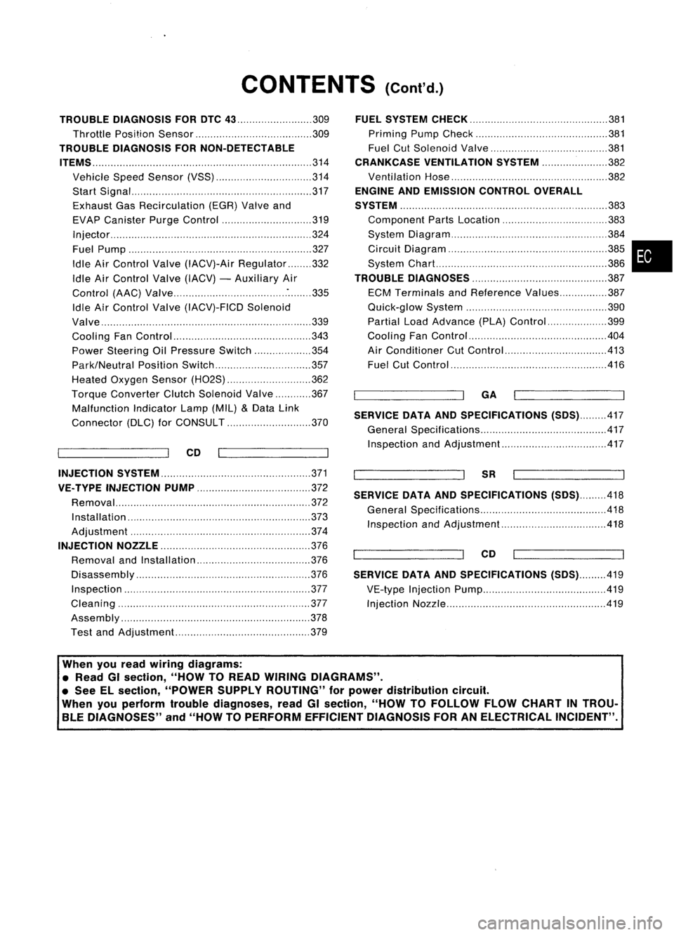
CONTENTS(Cont'd.)
TROUBLE DIAGNOSIS FORDTC
43 309
Throttle Position Sensor 309
TROUBLE DIAGNOSIS FORNON-DETECTABLE
ITEMS
314
Vehicle SpeedSensor (VSS) 314
Start Signal 317
Exhaust GasRecirculation (EGR)Valveand
EVAP Canister PurgeControl 319
Injector 324
Fuel Pump 327
Idle AirControl Valve(IACV)-Air Regulator 332
Idle AirControl Valve(IACV) -Auxiliary Air
Control (AAC)Valve :335
Idle AirControl Valve(IACV)-FICD Solenoid
Valve '"339
Cooling FanControl 343
Power Steering OilPressure Switch 354
Park/Neutral PositionSwitch 357
Heated Oxygen Sensor(H02S) 362
Torque
Converter
ClutchSolenoid Valve 367
Malfunction IndicatorLamp(MIL)
&
Data Link
Connector (DLC)forCONSULT 370
CD
INJECTION SYSTEM
371
VE.TYPE INJECTION PUMP
372
Removal 372
Installation 373
Adjustment 374
INJECTION NOZZLE
376
Removal andInstallation 376
Disassembly 376
Inspection 377
Cleaning 377
Assembly 378
Test andAdjustment 379
FUEL
SYSTEM CHECK
381
Priming PumpCheck 381
Fuel CutSolenoid Valve 381
CRANKCASE VENTILATION SYSTEM
382
Ventilation Hose 382
ENGINE ANDEMISSION CONTROLOVERALL
SYSTEM
383
Component PartsLocation 383
System Diagram 384
Circuit Diagram ,385
System Chart. 386
TROUBLE DIAGNOSES
387
ECM Terminals andReference Values 387
Quick-glow System 390
Partial LoadAdvance (PLA)Control 399
Cooling FanControl 404
Air Conditioner CutControl 413
Fuel CutControl 416
GA
SERVICE DATAANDSPECIFICATIONS
(505).417
General Specifications 417
Inspection andAdjustment.. 417
SR
SERVICE DATAANDSPECIFICATIONS
(505).418
General Specifications 418
Inspection andAdjustment.. .418
CD
SERVICE DATAANDSPECIFICATIONS
(505).419
VE-type Injection Pump 419
Injection Nozzle 419
•
When youread wiring diagrams:
• Read GIsection, "HOWTOREAD WIRING DIAGRAMS" .
• See Elsection, "POWER SUPPLYROUTING" forpower distribution circuit.
When youperform troublediagnoses, readGIsection, "HOWTOFOllOW FLOWCHART INTROU-
BLE DIAGNOSES" and"HOW TOPERFORM EFFICIENT DIAGNOSIS FORANELECTRICAL INCIDENT".
Page 723 of 1701
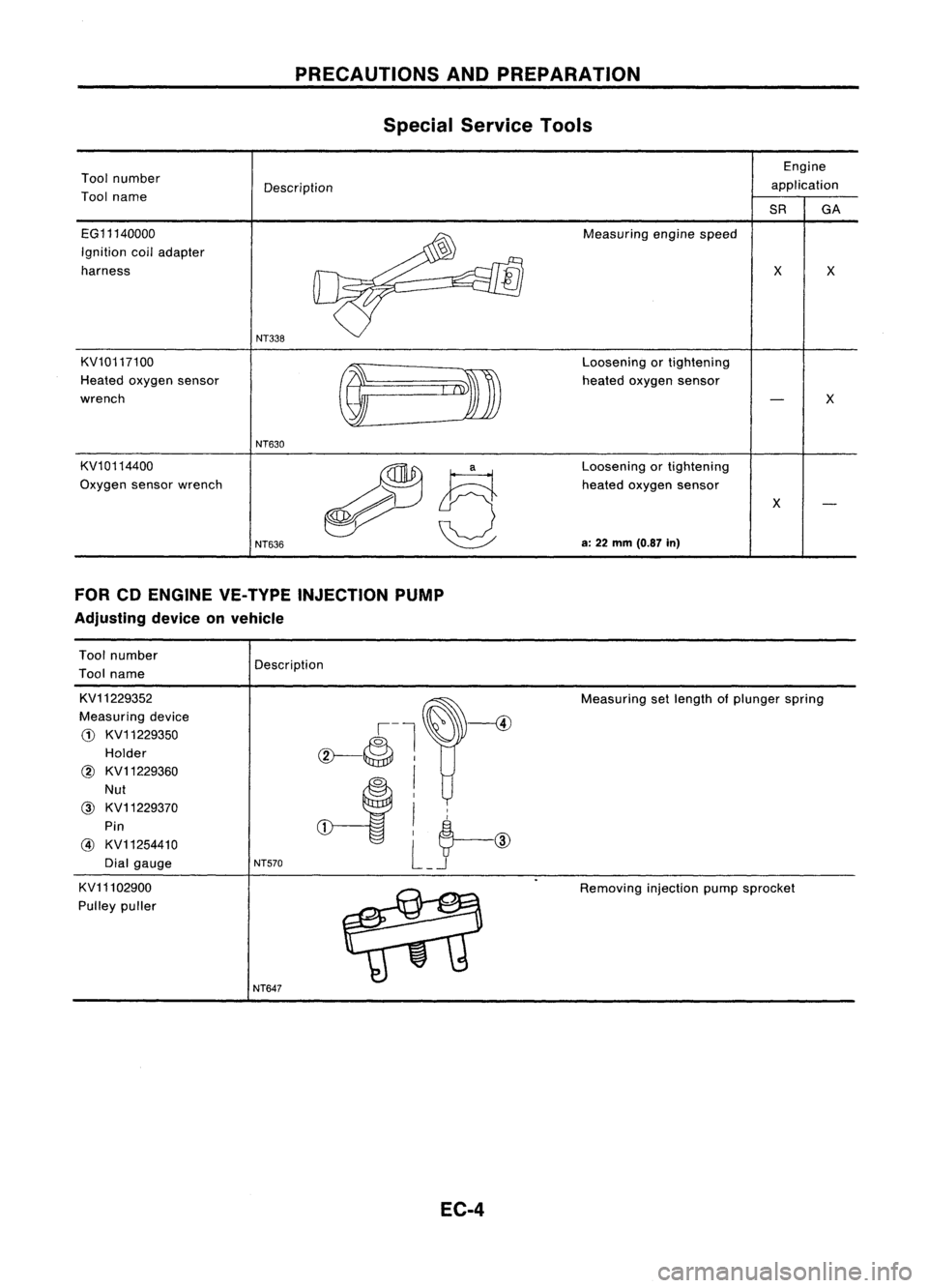
PRECAUTIONSANDPREPARATION
Special Service Tools
Tool number
Tool name Description Engine
application
SR GA
EG11140000
Ignition coiladapter
harness
KV10117100
Heated oxygen sensor
wrench
KV10114400
Oxygen sensorwrench
NT338
NT630
NT636
Measuring
enginespeed
Loosening ortightening
heated oxygen sensor
Loosening orlightening
heated oxygen sensor
a: 22 mm (0.87 in)
x
x
x
x
FOR CDENGINE VE-TYPE INJECTION PUMP
Adjusting deviceonvehicle
Tool number
Tool name Description
KV11229352
Measuring device
CD
KV11229350
Holder
@ KV11229360
Nut
@ KV11229370
Pin
@ KV11254410
Dial gauge
KV11102900
Pulley puller
NT570
NT647
EC-4
Measuring
setlength ofplunger spring
Removing injectionpumpsprocket
Page 724 of 1701
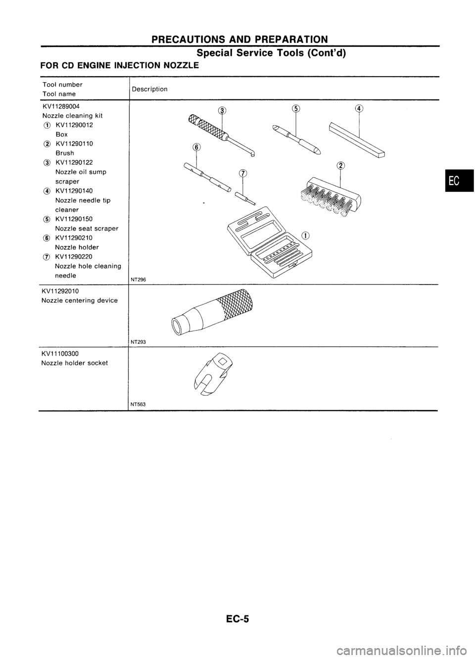
PRECAUTIONSANDPREPARATION
Special Service Tools(Cont'd)
FOR CDENGINE INJECTION NOZZLE
Tool number
Description
Tool name
KV11289004
Nozzle cleaning kit
CD
KV11290012
Box
@
KV11290110
Brush
@ KV11290122
Nozzle oilsump
•
scraper
@ KV11290140
Nozzle needle tip
cleaner
@
KV11290150
Nozzle seatscraper
@ KV11290210
Nozzle holder
!J) KV11290220
Nozzle holecleaning
needle
NT296
KV11292010
Nozzle centering device
NT293
KV11100300
Nozzle holdersocket
NT563
EC-5
Page 726 of 1701
PRECAUTIONSANDPREPARATION
Supplemental RestraintSystem(SRS)"AIR
BAG" (DualAirBag System)
The Supplemental RestraintSystem"AirBag", usedalong withaseat belt,helps toreduce therisk or
severity ofinjury tothe driver andfront passenger inafrontal collision. TheSupplemental Restraint
System consists ofair bag modules (locatedinthe center ofthe steering wheelandonthe instrument
panel onthe passenger side),adiagnosis sensorunit,warning lamp,wiring harness andspiral cable.
Information necessarytoservice thesystem safelyisincluded inthe
RSsection
ofthis Service Manual.
WARNING:
• Toavoid rendering theSRS inoperative, whichcouldincrease therisk ofpersonal injuryordeath
in the event ofacollision whichwould resultinair bag inflation, allmaintenance mustbeperformed
by an authorized NISSANdealer. •
• Improper maintenance, includingincorrectremovalandinstallation ofthe SRS, canlead topersonal
injury caused byunintentional activationofthe system.
• Donot use electrical testequipment ~nany circuit related tothe SRS unless instructed tointhis
Service Manual. SRSwiring harnesses arecovered withyellow insulation eitherjustbefore the
harness connectors orfor the complete harness,foreasy identification.
Supplemental RestraintSystem(SRS)"AIR
BAG" (Single AirBag System)
The Supplemental RestraintSystem"AirBag", usedalong withaseat belt, helps toreduce therisk or
severity ofinjury tothe driver inafrontal collision. TheSupplemental RestraintSystemconsists ofan
air bag module (located inthe center ofthe steering wheel),adiagnosis sensorunit,warning lamp,
wiring harness andspiral cable. Information necessarytoservice thesystem safelyisincluded inthe
RS section
ofthis Service Manual.
WARNING: • Toavoid rendering theSRS inoperative, whichcouldincrease therisk ofpersonal injuryordeath
in the event ofacollision whichwould resultinair bag inflation, allmaintenance mustbeperformed
by an authorized NISSANdealer.
• Improper maintenance, includingincorrectremovalandinstallation ofthe SRS, canlead topersonal
injury caused byunintentional activationofthe system.
• Donot use electrical testequipment onany circuit related tothe SRS unless instructed tointhis
Service Manual.
EC-7