1995 NISSAN ALMERA N15 service
[x] Cancel search: servicePage 218 of 1701
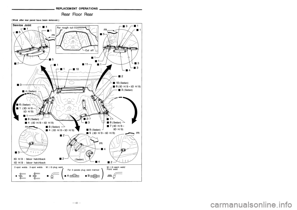
REPLACEMENTOPERATIONS
Rear Floor Rear ________
GENERALINFORMATION _
Identification Number(Cont'd)
(Work afterrearpanel havebeen removed.)
ExceptforEurope
IN 1 .B CAN 15A
0
XXXXXX
T
T
--c:::
serialnumber
0:
Stopgap (nomeaning)
Destination
A: Australia andNew Zealand
Z: Except forEurope, Australia, andNew Zealand
Model
A: 2-wheel drive
Engine type
B: GA 15DE engine
C: GA 16DE engine
E: SR20DE engine-For AustraliaandNew Zealand only
Body type
B: 4-door Sedan
F: 5-door Hatchback
Manufacturer
IN 1:Nissan, Passenger vehicle
VEHICLE IDENTIFICATION PLATE
1Type approval number
2 Vehicle identification
number(Chassis number)
3 Gross vehicle weight
4 Gross combination weight
Gross vehicle weight
+
Gross trailing capacity
(Weight)
5 Gross axleweight(Front)
6 Gross axleweight(Rear)
7 Type approval number
8 Body colorcode
9 Trim color code
10 Model Specification No.
11 Engine model
12 Engine displacement
13 Transaxle model
14 Axle model
cc
o
PLANT
PlANTA
El
ii:
13IJJ
if[
**
it~
*1
MADEINJAPAN
NISSAN
MOTORCO.,LTD. APAN
~ tt
~(:l
&
~~~sg~
CNHOA"SIS ~
~~~~~o
&
o ~
0
:ggtg~
~~~RNICION ~
&.
~~ ~~~~~ &
£
; ;~)~ /~~~~~'. AE~~
A1L11
Expect
Europe
~
&
kgO
1-
&
kg
2-
&
kg
COlOR. TRIM
~
&
FARBE. POlST
&
NISSAN
MOTORCO.,LTD. JAPAN
I ~ I
~
o
TYPE
TTP
Europe
FR
_2
3D
HI
B:3door hatchback
5D
HI
B:5door hatchback
Service
Joint
111
~
2-spot welds 3-spotwelds M.
I.
G plug weld .MIG seam weld/
(For 3panels plugweld method )P:
F
weld
• rr=- •
A
===-=
.'S~
.L.LLL
GTJ --- ~
-43-
-2-
Page 219 of 1701
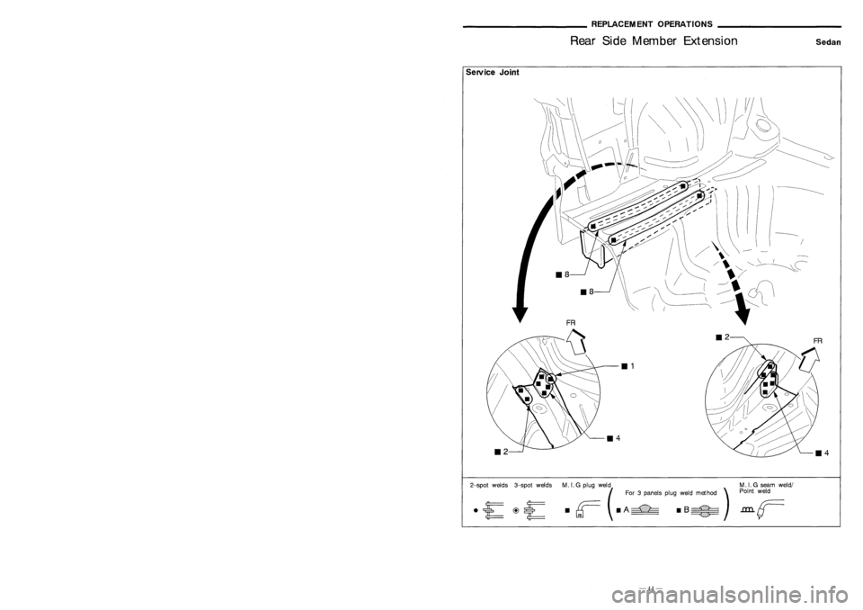
~~~~~~~~_GENERALJNFORM~ION~~~~~~~~_
IdentificationNumber _
REPLACEMENTOPERATIONS
Rear SideMember Extension
Sedan
-------
/
/\
---
/ \ -
'------- /~ ,,\I
c-
~ ~>~
111
114
Service
Joint
SGI908
Vehicle
identification plate
A
A
Vehicle
identification number
N15 U
0
xxxxxx.
T
T
---c::
serialnumber
0:
Stopgap (nomeaning)
Destination
U: Europe
Model
A: 2-wheel drive
Engine type
A: GA 14DE engine
C: GA 16DE engine
E: SR20DE engine
F: CD20 engine
Body type
B: 4-door Sedan
F: 5-door Hatchback
E: 3-door Hatchback
Manufacturer
J
N 1: Nissan, Passenger vehicle
Emission
controlinformation label
VEHICLE IDENTIFICATION NUMBERARRANGEMENT
For Europe
• JN1 B
2-spotwelds 3-spotwelds M.I.G plug weld
(For 3panels plugweld method )
d
r;==
dA~ dB~
GTJ ~
M.
I.G seam weld/
Point weld
-1-
-44-
Page 220 of 1701
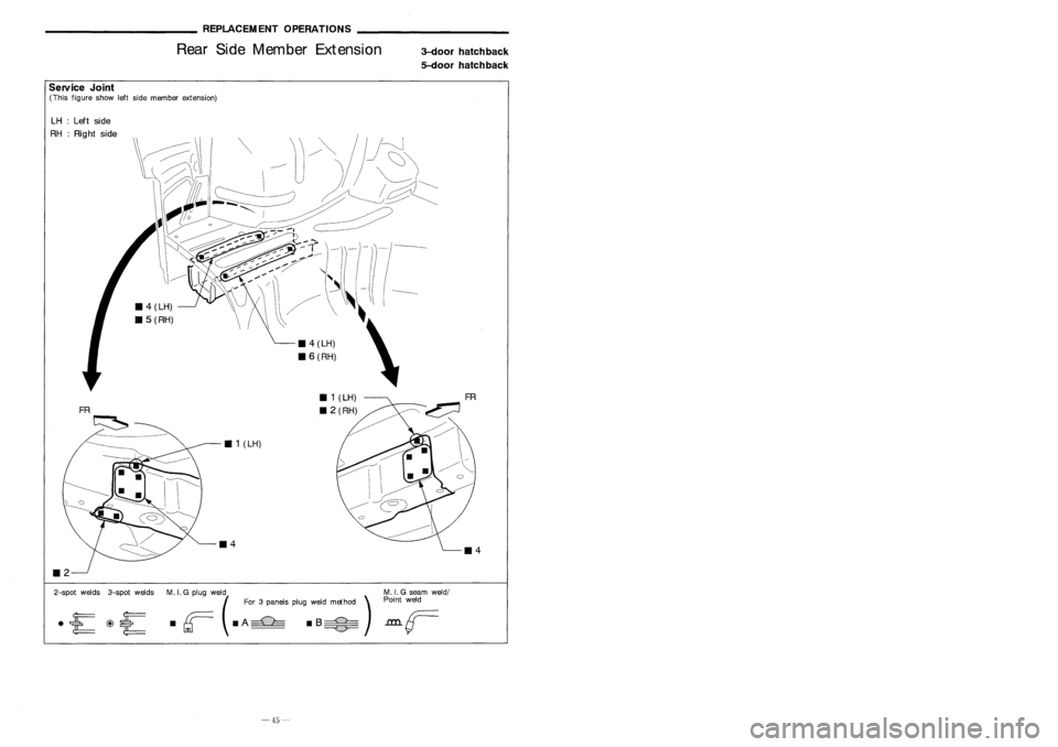
3-doorhatchback
5-door hatchback
___________
REPLACEMENTOPERATIONS _
Rear SideMember Extension
Service Joint
(This figure showleftside member extension)
FR
~
/
----
11 1
(LH)
11 2(RH)
_
4(LH)
_ 6
(RH)
111
(LH)
FR
~
LH
:Left side
RH :Right side
2-spot welds 3-spotwelds
M.I.G plug weld( For3panels plugweld method )
· r ·
A
===-= •
B:::::C=
M.
I.G seam weld/
Point weld
-45-
Page 221 of 1701
BODY
&
TRIM
SECTION
BT
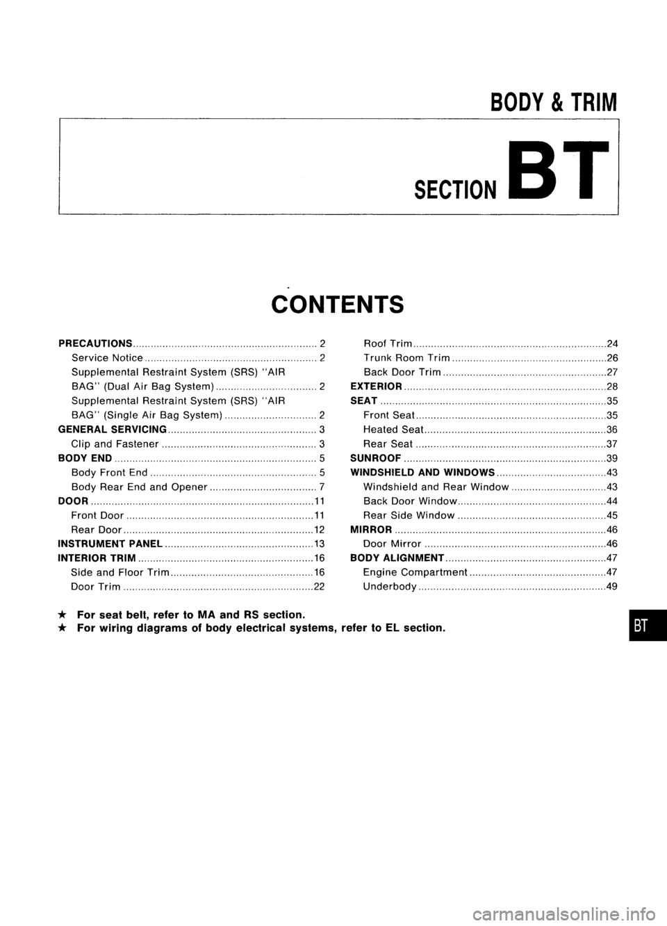
CONTENTS
* For seat belt,refer toMA and RSsection.
* For wiring diagrams ofbody electrical systems,refertoEL section.
PRECAUTIONS
2
Service Notice 2
Supplemental RestraintSystem(SRS)"AIR
BAG" (DualAirBag System) 2
Supplemental RestraintSystem(SRS)"AIR
BAG" (Single AirBag System) 2
GENERAL SERViCiNG 3
Clip andFastener
3
BODY END
5
Body Front End
5
Body RearEndandOpener 7
DOOR 11
Front Door 11
Rear Door
12
INSTRUMENT PANEL
13
INTERIOR TRIM 16
Side andFloor Trim
16
Door Trim 22Roof
Trim 24
Trunk RoomTrim 26
Back DoorTrim 27
EXTERIOR 28
SEAT 35
Front Seat
35
Heated Seal... 36
Rear Seat 37
SUNROOF 39
WINDSHIELD ANDWINDOWS 43
Windshield andRear Window 43
Back DoorWindow 44
Rear SideWindow
.45
MIRROR 46
Door Mirror .46
BODY ALIGNMENT 47
Engine Compartment 47
Underbody .49
•
Page 222 of 1701

PRECAUTIONS
Service Notice
• When removing orinstalling variousparts,placeacloth orpadding ontothevehicle bodytoprevent
scratches.
• Handle trim,molding, instruments, grille,etc.carefully duringremoving orinstalling. Becareful not
to soil ordamage them.
• Apply sealing compound wherenecessary wheninstalling parts.
• When applying sealingcompound, becareful thatthesealing compound doesnotprotrude from
parts.
• When replacing anymetal parts(forexample bodyouter panel, members, etc.),besure totake rust
prevention measures.
SupplementalRestraintSystem(SRS)"AIR
BAG" (DualAirBag System)
The Supplemental RestraintSystem"AirBag", usedalong withaseat belt,helps toreduce therisk or
severity ofinjury tothe driver andfront passenger inafrontal collision. TheSupplemental Restraint
System consists ofair bag modules (locatedinthe center ofthe steering wheelandonthe instrument
panel onthe passenger side),adiagnosis sensorunit,warning lamp,wiring harness andspiral cable.
Information necessarytoservice thesystem safelyisincluded inthe
RSsection
ofthis Service Manual.
WARNING:
• Toavoid rendering theSRS inoperative, whichcouldincrease therisk ofpersonal injuryordeath
in the event ofacollision whichwould resultinair bag inflation, allmaintenance mustbeperformed
by an authorized NISSANdealer.
• Improper maintenance, includingincorrectremovalandinstallation ofthe SRS, canlead topersonal
injury caused byunintentional activationofthe system.
• Donot use electrical testequipment onany circuit related tothe SRS unless instructed tointhis
Service Manual. SRSwiring harnesses arecovered withyellow insulation eitherjustbefore the
harness connectors orfor the complete harness,foreasy identification.
Supplemental RestraintSystem(SRS)"AIR
BAG" (Single AirBag System)
The Supplemental RestraintSystem"AirBag", usedalong withaseat belt,helps toreduce therisk or
severity ofinjury tothe driver inafrontal collision. TheSupplemental RestraintSystemconsists ofan
air bag module (located inthe center ofthe steering wheel),adiagnosis sensorunit,warning lamp,
wiring harness andspiral cable. Information necessarytoservice thesystem safelyisincluded inthe
RS section
ofthis Service Manual.
WARNING:
• Toavoid rendering theSRS inoperative, whichcouldincrease therisk ofpersonal injuryordeath
in the event ofacollision whichwould resultinair bag inflation, allmaintenance mustbeperformed
by an authorized NISSANdealer.
• Improper maintenance, includingincorrectremovalandinstallation ofthe SRS, canlead topersonal
injury caused byunintentional activationofthe system.
• Donot use electrical testequipment onany circuit related tothe SRS unless instructed tointhis
Service Manual.
BT-2
Page 271 of 1701
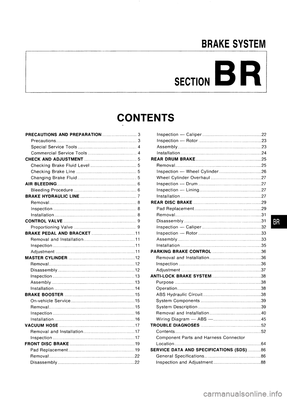
BRAKESYSTEM
SECTION
CONTENTS BR
PRECAUTIONS ANDPREPARATION
3
Precautions 3
Special Service Tools 4
Commercial ServiceTools 4
CHECK ANDADJUSTMENT 5
Checking BrakeFluidLevel 5
Checking BrakeLine 5
Changing BrakeFluid 5
AIR
BLEEDING 6
Bleeding Procedure 6
BRAKE HYDRAULIC LINE 7
Removal 8
Inspection 8
Installation 8
CONTROL VALVE 9
Proportioning Valve 9
BRAKE PEDALANDBRACKET 11
Removal andInstallation 11
Inspection 11
Adjustment 11
MASTER CYLINDER 12
Removal 12
Disassembly 12
Inspection 13
Assembly 13
Installation 14
BRAKE BOOSTER 15
On-vehicle Service 15
Removal 15
Inspection 16
Installation 16
VACUUM HOSE 17
Removal andInstallation 17
Inspection 17
FRONT DISCBRAKE 19
Pad Replacement.. 19
Removal 22
Disassembly 22Inspection
-Caliper 22
Inspection -Rotor 23
Assembly '".23
Installation 24
REAR DRUM BRAKE 25
Removal 25
Inspection -Wheel Cylinder 26
Wheel Cylinder Overhaul 27
Inspection -Drum 27
Inspection -Lining 27
Installation 27
REAR DISCBRAKE 29
Pad Replacement 29
~~s:~::~'~I~':::::::::::'::: ::.::::::::.::::::.::::::::::.::::::.::::::::~~ •••
Inspection -Caliper 32
Inspection -Rotor 33
Assembly 33
Installation 35
PARKING BRAKECONTROL 36
Removal andInstallation 36
Inspection 36
Adjustment ." 37
ANTI-LOCK BRAKESYSTEM 38
Purpose 38
Operation 38
ABS Hydraulic Circuit 38
System Components 39
System Description 39
Removal andInstallation .40
Wiring Diagram -ABS - .45
TROUBLE DIAGNOSES
52
Contents 52
Component PartsandHarness Connector
Location 64
SERVICE DATAANDSPECIFICATIONS (SDS)86
General Specifications 86
Inspection andAdjustment 88
Page 273 of 1701

PRECAUTIONSANDPREPARATION
Precautions
SUPPLEMENTAL RESTRAINTSYSTEM(SRS)"AIRBAG"
(DUAL AIRBAG SYSTEM)
The Supplemental RestraintSystem"AirBag" usedalong with
a seat belt,helps toreduce therisk orseverity ofinjury tothe
driver andfront passenger inafrontal collision. TheSupple-
mental Restraint Systemconsists ofair bag modules (located
in the center ofthe steering wheelandonthe instrument panel
on the passenger side),adiagnosis sensorunit,warning lamp,
wiring harness andspiral cable. Information necessarytoser-
vice thesystem safelyisincluded inthe
RSsection
ofthis Ser-
vice Manual.
WARNING:
• Toavoid rendering theSRS inoperatiYe, whichcouldincrease therisk ofpersonal injuryordeath
in the event ofacollision whichwould resultinair bag inflation, allmaintenance mustbeperformed
by an authorized NISSANdealer.
• Improper maintenance, includingincorrectremovalandinstallation ofthe SRS, canlead topersonal
injury caused byunintentional activationofthe system.
• Donot use electrical testequipment onany circuit related tothe SRS unless instructed tointhis
Service Manual. SRSwiring harnesses arecovered withyellow insulation eitherjustbefore the
harness connectors orfor the complete harness,foreasy identification.
SUPPLEMENTAL RESTRAINTSYSTEM(SRS)"AIRBAG"
(SINGLE AIRBAG SYSTEM)
The Supplemental RestraintSystem"AirBag" andused along withaseat belt,helps toreduce therisk
or severity ofinjury tothe driver inafrontal collision. TheSupplemental RestraintSystemconsists of
an air bag module (located inthe center ofthe steering wheel),adiagnosis sensorunit,warning lamp,
wiring harness andspiral cable. Information necessarytoservice thesystem safelyisincluded inthe
RS section
ofthis Service Manual.
WARNING:
• Toavoid rendering theSRS inoperative, whichcouldincrease therisk ofpersonal injuryordeath
in the event ofacollision whichwould resultinair bag inflation, allmaintenance mustbeperformed
by an authorized NISSANdealer.
• Improper maintenance, includingincorrectremovalandinstallation ofthe SRS, canlead topersonal
injury caused byunintentional activationofthe system.
• Donot use electrical testequipment onany circuit related tothe SRS unless instructed tointhis
Service Manual.
BR-3
•
Page 274 of 1701
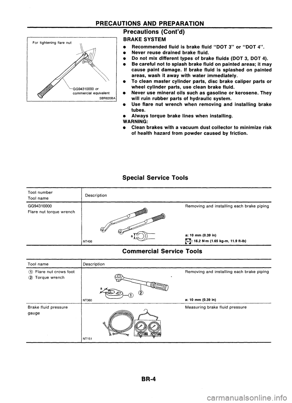
GG94310000or
commercial equivalent
SBR820BA
For
tightening flarenut
Tool number
Tool name
PRECAUTIONS
ANDPREPARATION
Precautions (Conl'd)
BRAKE SYSTEM
• Recommended fluidisbrake fluid"DOT 3"or"DOT 4".
• Never reusedrained brakefluid.
• Donot mix different typesofbrake fluids (DOT3,DOT 4).
• Becareful nottosplash brakefluidonpainted areas;itmay
cause paintdamage. Ifbrake fluidissplashed onpainted
areas, washitaway withwater immediately.
• Toclean master cylinder parts,discbrake caliper partsor
wheel cylinder parts,useclean brake fluid.
• Never usemineral oilssuch asgasoline orkerosene. They
will ruin rubber partsofhydraulic system.
• Use flare nutwrench whenremoving andinstalling brake
tubes.
• Always torquebrakelineswhen installing.
WARNING:
• Clean brakes withavacuum dustcollector tominimize risk
of health hazard frompowder causedbyfriction.
Special Service Tools
Description
GG9431 0000
Flare nuttorque wrench
NT406
Removing
andinstalling eachbrake piping
a: 10 mm (0.39 in)
~: 16.2N'm(1.65 kg-m, 11.9f1-lb)
Commercial ServiceTools
Description
Tool name
CD
Flare nutcrows foot
@ Torque wrench
Brake fluidpressure
gauge
NT360
NT151
Removing
andinstalling eachbrake piping
a: 10 mm (0.39 in)
Measuring brakefluidpressure
BR-4